Table of Contents
Advertisement
Quick Links
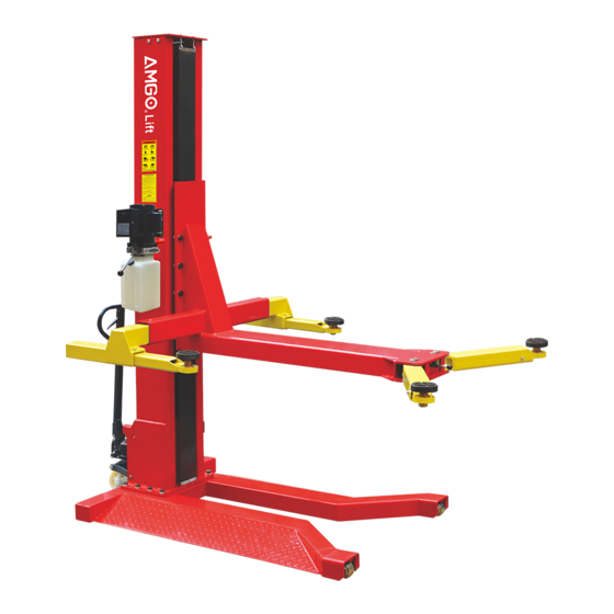
MOBILE SINGLE POST LIFT
Cargo Claims
If there is any missing or damaged
product during transportation, the
buyer must notate on the shipping
paperwork or refuse the shipment.
NOTATE ALL DAMAGE OR REFUSE
DAMAGED SHIPMENT!
Address:
SC Division: 1931 Joe Rogers Jr Blvd, Manning, SC 29102, USA
TX Division: 4310 Adler Dr., Suite #200, Dallas, TX 75211, USA
Model: SML-7
△
DANGER
!
Read the entire contents of this manual before
using this product. Failure to follow instructions
and safety precautions could result in serious
injury or even death. Make sure all other
operators also read this manual. Keep this
manual near the machine so that it can be seen
by all users. By proceeding with installation and
operation, you agree that you are fully
understand the contents of this manual and take
full responsibility for the use of the product.
Original
Advertisement
Table of Contents

Related Manuals for AMGO SML-7


Summary of Contents for AMGO SML-7
- Page 1 Original MOBILE SINGLE POST LIFT Model: SML-7 △ DANGER Read the entire contents of this manual before using this product. Failure to follow instructions Cargo Claims and safety precautions could result in serious injury or even death. Make sure all other If there is any missing or damaged operators also read this manual.
-
Page 2: Table Of Contents
CONTENTS PROFILE ..................1 IMPORTANT SAFETY INSTRUCTIONS ..........3 I. PRODUCT FEATURES AND SPECIFICATIONS ........5 II. INSTALLATION REQUIREMENT .............8 III. INSTALLATION STEPS ...............19 IV. EXPLODED VIEW ..............23 V. TEST RUN .................26 VI. OPERATION INSTRUCTIONS ............27 VII. MAINTENANCE SCHEDULE ............28 VIII. TROUBLE SHOOTING .............29 IX. -
Page 3: Profile
PROFILE This installation and service manual is specially prepared for you. Your new lift is the product of over a decade of continuous research, testing and development and is the most technologically advanced lift on the market today. Please make sure to read through this manual before operating the lift. Record the information on the nameplate label here: Model No.:___________________ Serial No.:___________________... - Page 4 SAFETY WARNING LABEL Fig.1...
-
Page 5: Important Safety Instructions
IMPORTANT SAFETY INSTRUCTIONS In order to properly maintain your product and ensure operator safety, it is the responsibility of the product owner to read and follow these instructions! 1. Ensure product installation full complies with all applicable local and national rules, ordinances and regulations;... - Page 6 18. Check for damaged parts. Check for adjustments to moving parts, damage to parts, or anything that may affect their operation. Do not use the machine if the parts are damaged; 19. Do not remove relevant safety parts from the machine. Do not use a lift if it is damaged or missing;...
-
Page 7: Product Features And Specifications
I. PRODUCT FEATURES AND SPECIFICATIONS Fig.2 MOBILE SINGLE POST MODEL SML-7 FEATURES · Lifting capacity: 7000lbs · Compact design. · Hydraulic cylinder is designed and made on high standard, with utilizing imported oil seal in cylinder. · Self-lubricating UHMW polyethylene sliders and bronze bush. - Page 8 MODEL SML-7 SPECIFICATIONS Arm Swings View Fig.3 Lifting Model Lifting Time Capacity Overall Minimum Overall Width Max. Lifting Height Height Pad Height Without extension Include extension adapter adapters 84S(110V) 7000lbs SML-7 108 7/8" 90 3/8" 4 3 /8" 32S (220V) 72 1/4"~74 13/16"...
-
Page 9: Installation Requirement
II. INSTALLATION REQUIREMENT A. TOOLS REQUIRED Screw sets Level Bar Tape Measure(7.5m) Spanner Wrench(12″) Pliers Wrench set:(10 Socket Head Wrench:(4 # # # # # # # 、13 、14 、12 、5 、6 # # #... -
Page 10: Installation Steps
C. Power supply 1.You are required to use a licensed and qualified electrician for the installation process. 2.The power supply should be 110VAC/60HZ, with a cord larger than 12AWG, and must be properly grounded. △ DANGER All electrical wiring must be performed by a licensed and certified electrician. - Page 11 ⚠ CAUTION Installing the lift on a surface with slopes more than 3° could lead to injury or even death. The lift is designed for installation on a flat and level surface only. (Defined as no more than 3/8” difference over the installation area ). If the floor cannot be leveled, consider changing installation locations.
- Page 12 4. Open the parts box, and check all the parts according to the parts list. Fig.8 5. Open parts bag 1 & parts bag 2, check all the parts according to the parts bag list. Parts bag Parts bag Fig.9 C.
- Page 13 D. Install column, connect cylinder oil hose and install lift platform 1.Lay the column flat to the ground. (See Fig.11) Fig.11 2.Connect oil hose to cylinder. (See Fig.12) Fig.12 B: Pass the oil hose through the hole on A: Pull out the carriage around 8" the backside of column and connect it (200mm) from base plate.
- Page 14 4. Fix lifting platform to carriage. (See Fig.14) M20*40 hex bolt w/ flat washer, lock washer,nut Fig.14 E. Install power unit, retainer and connect oil hose. Install power unit. See fig 15. M8*25 hex bolt w/ φ 20* φ 8*3 rubber ring, M8 nylok nut Fig.15...
- Page 15 2. Connect oil hose. Install the 90° fitting to the power unit, then connect it with the oil hose that comes from the cylinder. 90°fitting for power unit Fig.16 3. Install retainer M6*8 cup head bolt φ6 flat washer Fig.17 Note: Tighten all the hydraulic fittings after installation.
- Page 16 F. Connect the power with schematic circuit diagram according to the requirement on the motor plate. Note: To ensure the safety of operators, the lift must be grounded. Test the lift after installation to check if works fine. Single phase motor (see fig 18) Connect the two hot wires of power supply respectively to the terminals of AC contactor marked L1 and L3 .
- Page 17 G. Install safety device cover (see fig.19) M6*8 cup head bolt w/ flat washer Fig.19 H. Install lifting arms. 1. Install inside lifting arms. Insert the inside lifting arm into square tube, tighten with M8*20 limit bolt to prevent the lifting arms from pulling out.
- Page 18 2. Install outside lifting arms. Align the outside lifting arm with the hole, then insert the arm pin, and tighten with M8*12 flat head bolt. See fig 21. M8*12 flat head bolt Arm pin Fig.21 3. Operation of arm lock release handle Fig.22 ②...
- Page 19 I. Install fabric curtain cover . See fig 23. Follow the steps below to install the fabric curtain cover. M6*95 hook bolt, w/ φ6 flat washer and M6 nylok Just assemble the nut to flush with the hook bolt, don’t tighten yet 1.Install the hook bolt into the top plate.
- Page 20 J. Install mobile wheel dolly. Please install following the below steps. M12*20 socket bolt w/ flat washer, lock washer 2. Connect the dolly fixing square tube and the 1. Assemble the dolly fixing square tube (50) dolly connecting board (44) with pin, and limit to the mounting plate at the backside of with clip ring at both ends.
-
Page 21: Exploded View
IV. EXPLOEDED VIEW Fig.29... - Page 22 PARTS LIST FOR SML-7 Item Part# Description 11101013 Top plate 1001085013 M12*30 hex bolt w/ M12 nylok nut 1101085015 Hook bolt M6*95 w/ φ6 flat washer, M6 Nylok Nut 11101042 Fabric curtain cover L=101 3/16"(2570mm) 11207681 Chain pulley seat assy.
- Page 23 Item Part# Description M20*40 hex bolt w/ φ20 flat washer, φ20 lock washer 1001085008 and M20 nut) 11102010 Dolly connecting pin φ19*376 10206019 Clip ring φ19 11101030 Dolly connecting plate 10101039 Dolly limit pin φ16*49 10420029 Flat washer φ16 10101038 Snap Pin φ5*40 10101028 Dolly cylinder assy.
- Page 24 4.1 Rubber pad assy. (10203054) exploded view: Description Item Part# 10420043 M8*20 Socket bolt 10203043 Double screwed rubber pad 11203026 Support frame 10203041 Snap ring 11203025 Adjusting rod 10203042 Snap ring 11203024 Adjusting sleeve Fig.30 4.2 Outside arm assy. (10101033) exploded view: Fig.31 Description Item...
- Page 25 4.3 Inside arm assy. (left) (10102028)exploded view: Fig. 32 Part# Description QTY. 10201149 M8*12 cup head bolt 11102610 Outer arm 11203101A Inner Arm 4.4 Inside arm assy. (right) (10102029)exploded view: Fig. 33 Item Part# Description QTY. 10201149 M8*12 cup Head Bolt 11102612 Outer arm 11203101A...
- Page 26 4.5 Chain pulley seat assy. (11207681) exploded view: Fig. 34 Item Part# Description QTY. 11207006 Pin for Chain Pulley Φ35*93 10420132A Bronze bush Φ41.2*Φ35.1*20 11530023 Flat washer Φ44*Φ35.5*2 11207007 Chain Pulley Φ105*50 10430138 M6*15 hex bolt w/ flat washer, lock washer 11207693 Chain limit block 10530042...
- Page 27 Item Part# Description QTY. 11207027 Piston rod 11207028 Piston 10206069 O-Ring 10620053 Support ring 10620054 Y-ring OSI 10630027 O-ring 10206071 Hex Nut 11207029 Cylinder adjusting sleeve 10217078 Dust ring 10520058 O-ring 11207030 Head cap 10201034 Bleeding plug 10207031 O-ring 11207032 Bore weldment Illustration of hydraulic valves for power unit UP button...
-
Page 28: Test Run
V. TEST RUN 1. Adjust the lowering speed (Fig.37) If necessary, you can adjust the lowering speed of the lift by turning the throttle valve clockwise to decrease it, or counterclockwise to increase the lower speed. Throttle valve Throttle valve Fig.37 Counterclockwise to increase lowering speed. -
Page 29: Operation Instructions
△ WARNING Do not lift vehicles that exceed the rated capacity of the lift. Please do not release the safety handle until the lift safety lock is locked. Only trained personnel are authorized to operate the lift. VI. OPERATION INSTRUCTIONS To lift vehicle 1. -
Page 30: Maintenance Schedule
VII.MAINTENANCE SCHEDULE Monthly: 1. Tighten all connecting bolts; 2. Check all fitting, bolts and pins to ensure proper connections; 3. Lubricate slider, chain with lubricant; 4. Make a visual inspection of all hydraulic hoses/lines for possible wear or leakage; 5. Check safety device and make sure in proper condition; 6. -
Page 31: Trouble Shooting
VIII. TROUBLE SHOOTING TROUBLE CAUSE REMEDY 1.Button does not work 1. Replace 2.Wiring connections are not in good 2. Repair all wiring connections condition Motor does 3. AC contractor burned out 3. Replace not run 4. Motor burned out 4. Repair or replace 1. -
Page 32: Car Lift Safety Tips
IX. CAR LIFT SAFETY TIPS Post these safety tips in a place where you can always alert the operator. Please reference to the lift manufacturer’s manual for specific information about the lift. 1. Check the lift daily. If the machine breaks down or has damaged parts, do not operate, and use the parts of original equipment to repair;... - Page 33 No:72115209 Date:2023/10...
Need help?
Do you have a question about the SML-7 and is the answer not in the manual?
Questions and answers