Table of Contents
Advertisement
Quick Links
Advertisement
Table of Contents

Related Manuals for AMGO SL-7


Summary of Contents for AMGO SL-7
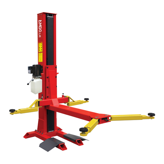
- Page 1 Original SINGLE POST LIFT Model:SL-7...
-
Page 2: Table Of Contents
CONTENTS PRODUCT FEATURES AND SPECIFICATIONS............1 INSTALLATION REQUIREMENT................3 STEPS OF INSTALLATION..................5 EXPLODED VIEW....................13 TEST RUN......................22 OPERATION INSTRUCTIONS................23 MAINTENANCE SCHEDULE..................24 TROUBLE SHOOTING..................25 LIFT DISPOSAL....................25... -
Page 3: Product Features And Specifications
I. PRODUCT FEATURES AND SPECIFICATIONS CHAIN-DRIVE SINGLE POST MODEL SL-7 FEATURES . Compact design. · High quality cylinders and power units are manufactured to high standards. . Self-lubricating UHMW Polyethylene sliders and bronze bush. . Manual release safety lock, two-stage lock system . - Page 4 Arm Swings View Fig.2...
-
Page 5: Installation Requirement
II. INSTALLATION REQUIREMENT A. TOOLS REQUIRED Rotary Hammer Drill(Φ19) Carpenter’s Chalk Hammer Screw sets Level Bar Tape Measure(7.5mm) English Spanner(12″) Pliers Wrench set:(10 Socket Head Wrench:(4 # # # # # #... - Page 6 B. Equipment storage and installation requirements. The equipment should be stored or installed in a shady, normal temperature, ventilated and dry place. C. SPECIFICATIONS OF CONCRETE (See Fig. 4) Specifications of concrete must be adhered to the specification as following. Failure to do so may result in lift and/or vehicle falling.
-
Page 7: Steps Of Installation
III. STEPS OF INSTALLATION A. Location of installation Check and insure the installation location (concrete, layout, space size etc.) is suitable for lift installation. B. Check the parts before assembly 1. Packaged lift and hydraulic power unit (See Fig. 5) Column Power Unit Base... - Page 8 2. Take off the packaging on the machine. Take off the packing rack. 3. Move aside the parts and check the parts according to the shipment parts list. (See Fig.6 & 7) Fig.6 Part box (65) Fig.7 4. Check the parts of the parts bag according to the parts bag list (See Fig.8) Fig.8...
- Page 9 C .Lay the base on the ground, confirm installation place according to the ground state, the main purpose is to save space. (See Fig.9) Fig. 9 D. Install column and lift platform 1. Lay the column on the ground. (See Fig.10) Fig.
- Page 10 3. Fix column to the base plate. (See Fig.12) 4. Fix lifting platform to carriage. (See Fig.13) Fig. 13 Fig. 12...
- Page 11 E. Install safety device, power unit, oil hose and wire holder (See Fig.14) Note: Tighten the oil hose fitting and power unit fitting to avoid oil leakage; Pay attention to the direction of power unit fitting. Tighter the screw with 19# wrench set after install power unit fitting.
- Page 12 F. Install plastic barrier (See Fig.15) Clip support The plastic barrier passes through here Fig. G. Install electrical system Connect the power source on the data plate of power unit. Note: For the safety of operators, the power wiring must contact the earth well. Single phase motor power supply wires (active wire L and neutral wire N) to terminals of AC contactor marked L1, L3 respectively.
- Page 13 H. Install lifting arms (see Fig.17); Lowing the carriages down to the lowest position, then use the 6# wrench to loosen the nut (See Fig. 18) Adjust the arm lock as arrow direction (See Fig. 19). Adjust moon gear and arm lock to make it to be good engagement, then tighten the nut of arm lock (See Fig.
- Page 14 I. Tighten all the hydraulic fittings, and fill the reservoir with hydraulic oil. Note: In consideration of Hydraulic Power Unit’s durability and keep the equipment running in the perfect condition, please use Hydraulic Oil 46#. J. Using level to measure and adjust the column to be vertical. Use level to measure the column by front and side to make sure...
-
Page 15: Exploded View
IV. Exploded View Model:SL-7 14~18 19~22 25~27 Fig.25... - Page 16 PARTS LIST FOR SL-7 Note Item Part# Description Top Plate assembly 11101013 10206023 Self-Locking Nut M12 Hex Bolt M12*30 10217069 Cap Head Bolt M6*8 10209009 10209012 Spring Pin (φ3.2) Power Side Safety Device 11203263 Safety Spring (120°angle) 10209007 11209008 Safety Cover...
- Page 17 Note Item Part# Description 10209023A Arm lock Limit Shim 11201041 Arm Lock Bar 11101010 10101034 Outside arm assy. 10520023 Snap ring φ38 11209030A Arm pin 10420175A Hex nut M20 10101001 Hex Bolt M20*45 11101016-01 Platform 10209025 Spring pin φ4*25 10209026 Safety spring φ1.4 10203054 Rubber pad assy.
- Page 18 1. Rubber Pad Assembly(10203054)exploded view: Fig.25 Description Item Part# 10420043 Hex Bolt M8*20 Rubber pad 10203043 Support pad assy. 11203026 10203041 Retaining ring 11203025 Adjusting screw 10203042 Retaining ring 11203024 Adjustment Screw 2. Outside Arm Assembly (10101033)exploded view Fig.26 Description Item Part# 10209032...
- Page 19 3. Inside Arm Assembly (10101034) exploded view: Fig.27 Description Item Part# 10209032 Socket bolt M8*25 10209034 Lock Washer φ8 10209033 Washer φ8 10209035 Moon gear 11203101 Outer arm - Inside 10201149 Cup head bolt M8*12 11102006 Inner arm - Inside 4.
- Page 20 Description Item Part# 11207027 Piston Rod 11207028 Piston 10206069 O-Ring 10620053 Support Ring 10620054 Y-Ring OSI 10630027 O-ring 10206071 Hex Nut 11207029 Adjustment Tube Cylinder Adjustment 10217078 Dust Ring 10520058 O-Ring 11207030 Head Cap 10201034 silencer 10207031 O-Ring 11207032 Cylinder Tube :...
- Page 21 6 Exploded view of manual power unit 220V/60Hz/1 phase 110V/60Hz/1 phase Fig.31 Fig.30 071104 071103 Manual Power Unit 110V/60Hz/1 Phase Item Part# Description Rubber pad 81400180 Start capacitor 81400250 81400200 Running capacitor 10420148 Cup Head Bolt with Washer Cover of capacitor 81400066 Motor connecting shaft 81400363...
- Page 22 Item Part# Description Cover of Motor Terminal Box 81400287 AMGO Sticker 71111211 81400560 Throttle valve 81400266 Relief valve 81400284 Plug 81400452 Handle for release valve 81400451 Plastic ball 10209020 Nut for release valve 81400421 Shim for release valve 81400422 Valve seat(short)
- Page 23 81400567 Release valve 81400566 Check valve 81400375 Oil suction pipe 81400376 Oil return pipe 81400364 Clamps(stainless steel) 81400263 Oil tank cap 81400320 Oil tank Illustration of hydraulic valve Relief valve return Release valve Throttle valve Handle Oil output port Oil output port Check valve Fig.32...
-
Page 24: Test Run
V. TEST RUN Adjust the lower speed (See Fig.34) Users can adjust the descending speed according to their needs. Adjust the throttle valve core clockwise. At this time, the descending speed becomes slower, and vice versa. Throttle valve Throttle valve Clockwise to decrease Counterclockwise to increase the lowering speed... -
Page 25: Operation Instructions
VI. OPERATION INSTRUCTIONS To lift vehicle 1. Keep clean of site near the lift; 2. Position lift arms to the lowest position; 3. To shortest lift arms; 4. Open lift arms; 5. Position vehicle beside of the lifting arm, car should at the other side of the column; Move arms to the vehicle’s lifting point;... -
Page 26: Maintenance Schedule
VII. MAINTENANCE SCHEDULE Monthly: 1.Re-torque the anchor bolts to 150 N.M; 2.Check all connectors, bolts and pins to insure proper mounting; 3.Lubricate cable with lubricant; 4.Make a visual inspection of all hydraulic hoses/lines for possible wear or leakage; 5.Check Safety device and make sure proper condition; 6.Lubricate all Rollers and Pins with 90wt. -
Page 27: Trouble Shooting
VIII. TROUBLE SHOOTING TROUBLE CAUSE REMEDY Button does not work 1. Replace button Wiring connections are not in good 2. Repair all wiring connection condition Motor does AC contactor burned out 3. Repair or replace contactor not run Motor burned out 4. - Page 28 Address: 1931 Joe Rogers Blvd, Manning, South Carolina,USA No:72210408 Date:2022/08...
Need help?
Do you have a question about the SL-7 and is the answer not in the manual?
Questions and answers