Sign In
Upload
Manuals
Brands
IEI Technology Manuals
Touch Panel
PPC2-CW123-EHL
IEI Technology PPC2-CW123-EHL Manuals
Manuals and User Guides for IEI Technology PPC2-CW123-EHL. We have
1
IEI Technology PPC2-CW123-EHL manual available for free PDF download: User Manual
IEI Technology PPC2-CW123-EHL User Manual (134 pages)
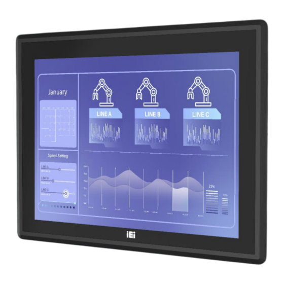
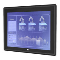
Panel PC equips Intel® Celeron® J6412 processor, on-board 8GB memory, HDMI display output, dual 2.5G Ethernet port, one M.2 M key & one M.2 B key expansion slots, 12~24V DC input, anti-glare and anti-UV 10-point touchscreen
Brand:
IEI Technology
| Category:
Touch Panel
| Size: 6 MB
Table of Contents
Table of Contents
7
1 Introduction
14
Figure 1-1: PPC2-CW123/133-EHL Panel PC
15
Table 1-1: Model Variation
16
Front Panel
17
Rear Panel
17
Overview
15
Features
16
Model Variation
16
Figure 1-3: PPC2-CW123-EHL Rear View
17
Figure 1-2: Front View
17
Bottom Panel
18
Figure 1-5: PPC2-CW123-EHL Bottom View
18
Figure 1-7: PPC2-CW123-EHL Dimensions (MM)
20
Figure 1-8: PPC2-CW133-EHL Dimensions (MM)
21
PPC2-CW133-EHL Dimensions
21
Specifications
21
Figure 1-4: PPC2-CW133-EHL Rear View
18
Figure 1-6: PPC2-CW133-EHL Bottom View
19
Dimensions
20
PPC2-CW123-EHL Dimensions
20
Table 1-2: PPC2-CW123/ PPC2-CW133 Specifications
23
2 Unpacking
24
Unpacking
25
Packing List
26
Optional Items
26
Table 2-1: Packing List
26
3 Installation
27
Anti-Static Precautions
28
Installation Precautions
28
Installation and Configuration Steps
29
Preinstalled Components
29
Figure 3-1:PPC2-CW123-EHL Back Cover Retention Screws
30
Figure 3-2: PPC2-CW133-EHL Back Cover Retention Screws
30
Figure 3-3: M.2 Slot Location
31
Figure 3-5: Insert M.2 Card
32
Figure 3-6: Securing the M.2 Card
32
Figure 3-7: AT/ATX Mode Selection
33
Table 3-1: AT/ATX Mode Selection
33
Mounting the System
34
Wall Mounting
34
Figure 3-8: Wall-Mounting Bracket
35
Figure 3-9: Mount the Chassis
36
Figure 3-10: Secure the Chassis
37
Figure 3-11: PPC2-CW123/133-EHL Panel Mount Kit Installation
38
Panel, Rack and Cabinet Installation
38
Figure 3-12: PPC2-CW123-EHL Panel Cutout Dimensions
39
Figure 3-14: Machine Mounted to Panel
40
Figure 3-15: Installation Panel Mount Kit
40
Figure 3-16: Tighten the Mounting Screws
41
Figure 3-17: Install into a Rack/Cabinet
41
Figure 3-18: Arm Mounting Retention Screw Holes
43
Figure 3-19: Arm Mounting (ARM-XX-RS)
43
Stand Mounting
43
Figure 3-20: Stand Mounting Retention Screw Holes
44
Figure 3-21: Stand Mounting (Stand-CXX)
44
Serial Device Connection
44
Figure 3-22: Serial Port Locations of PPC2-CW123-EHL
45
Figure 3-23: Serial Port Locations of PPC2-CW133-EHL
45
Serial Ports
45
Table 3-2: RS-232 Serial Port Pinouts
45
Figure 3-24: Power Input Connector Pinouts
46
Powering on the System
46
RS-232/422/485 Serial Port
46
Table 3-3: RS-232/422/485 Serial Port (COM3) Pinouts
46
Figure 3-25: Power Connectors and Power Switch
47
Figure 3-26: Reset Button Location
47
Reset the System
47
Clear Cmos
48
Figure 3-27: Clear CMOS Button Location
48
Available Drivers
49
Figure 3-28: IEI Resource Download Center
49
Driver Download
50
Figure 3-13: PPC2-CW133-EHL Panel Cutout Dimensions
39
Arm Mounting
42
Module Installation (Optional)
30
Removing the
30
Figure 3-4: Press the End of the M.2 Retaining Clip
31
At/Atx Mode Selection
33
4 System Maintenance
52
System Maintenance Introduction
53
Motherboard Replacement
53
5 Bios
54
Figure 5-1: BIOS Starting Menu
55
Introduction
55
Starting Setup
55
Table 5-1: BIOS Navigation Keys
56
Using Setup
56
Keyboard Navigation
56
Table 5-2: BIOS On-Screen Navigation Keys
57
Touch Navigation
57
BIOS Menu Bar
58
Getting Help
58
Unable to Reboot after Configuration Changes
58
Main
59
Advanced
61
Case Open Detection
62
CPU Configuration
63
Trusted Computing
67
RTC Wake Setting
68
F81966 Super IO Configuration
70
Serial Port 1 Configuration
71
Serial Port 2 Configuration
73
Serial Port 4 Configuration
74
Serial Port 5 Configuration
75
Serial Port 6 Configuration
76
H/W Monitor
77
Smart Fan Mode Configuration
79
Serial Port Console Redirection
80
Console Redirection Settings
81
Nvme Configuration
84
Chipset
84
System Agent (SA) Configuration
86
Graphics Configuration
87
Memory Configuration
87
PCH-IO Configuration
91
PCI Express Configuration
93
Pcie Root Port Setting
93
SATA Configuration
96
HD Audio Configuration
98
Security
99
Boot
101
Boot Configuration
101
Boot Option Priorities
102
Save & Exit
103
6 Interface Connectors
105
Figure 6-1: Main Board Layout Diagram (Front Side)
106
Figure 6-2: Main Board Layout Diagram (Solder Side)
106
Table 6-1: Peripheral Interface Connectors
107
Battery Connector (BAT2)
108
Capacitive Touch Port (TOUCH_USB)
108
EC Debug Port (EC_DEBUG1)
108
Fan Connector (CPU_FAN1)
108
SPI Flash Connector (JBIOS1)
108
Peripheral Interface Connectors
106
Internal Peripheral Connectors
107
Table 6-2: Fan Connector (CPU_FAN1) Pinouts
108
Table 6-3: Battery Connector (BAT2) Pinouts
108
Table 6-4: EC Debug Port (EC_DEBUG1)
108
Table 6-5: SPI Flash Connector (JBIOS1) Pinouts
108
Table 6-6: Capacitive Touch Port (TOUCH_USB) Pinouts
109
Table 6-7: SATA 6Gb/S Connectors (SATA2) Pinouts
109
Table 6-8: SATA Power Connectors (SATA2_PWR) Pinouts
109
Table 6-9: Resistive Touch Port (DMC6000_CN1) Pinouts
109
Table 6-10: ISATA Connector (SATA1) Pinouts
110
M-Key Slot (M2_M1)
111
Table 6-11: M.2 B-Key Slot (M2_1) Pinouts
111
IDPM Connector (J_M2_EDP_LVDS)
112
Table 6-12: M.2 M-Key Slot (M2_M1) Pinouts
112
Chassis Intrusion (CHASSIS1)
114
Debug Port (DBG_PORT1)
114
Flash Mode Connector (J_FLASH1)
114
SPI Flash (EC) Connector (EC_SPI1)
114
B-Key Slot (M2_1)
110
ISATA Connector (SATA1)
109
Resistive Touch Port (DMC6000_CN1)
109
SATA 6Gb/S Connectors (SATA2)
109
SATA Power Connectors (SATA2_PWR)
109
Table 6-16: Chassis Intrusion (CHASSIS1) Pinouts
114
Table 6-15: SPI Flash (EC) Connector (EC_SPI1) Pinouts
114
Table 6-17: Debug Port (DBG_PORT1) Pinouts
114
Table 6-19: Rear Panel Connectors
115
Table 6-18: Reset Button Connector (RST_BTN2) Pinouts
115
Gbe Connector (LAN1, LAN2)
116
Table 6-20: HDMI Connector (HDMI1) Pinouts
116
Table 6-22: USB 2.0 Connectors (USB2_CON1) Pinouts
116
Table 6-21: 2.5Gbe Connector (LAN1, LAN2) Pinouts
116
USB 2.0 Connectors (USB2_CON1)
116
USB 3.2 Gen 1 Connector (USB3_CON1)
116
Table 6-14: Flash Mode Connector (J_FLASH1) Pinouts
114
Table 6-13: IDPM Connector (J_M2_EDP_LVDS) Pinouts
114
External Interface Panel Connectors
115
HDMI Connector (HDMI1)
115
Power Button Connector (PWR_BTN1)
115
Table 6-23: USB 3.2 Gen 1 Connector (USB3_CON1)
117
A Regulatory Compliance
118
B Safety Precautions
123
Safety Precautions
124
General Safety Precautions
124
Anti-Static Precautions
125
Product Disposal
126
Maintenance and Cleaning Precautions
127
Maintenance and Cleaning
127
Cleaning Tools
127
C Watchdog Timer
129
D Hazardous Materials Disclosure
132
Advertisement
Advertisement
Related Products
IEI Technology PPC2-CW19-ADL
IEI Technology PPC2-CW133-EHL
IEI Technology PPC2-CW133-ADLP-i5/8G
IEI Technology PPC2-CW133-ADLP-i7/8G
IEI Technology PPC2-CW156-ADLP-i3/8G
IEI Technology PPC2-CW156-ADLP-i7/8G
IEI Technology PPC2-CW185-ADLP-i3/8G
IEI Technology PPC2-CW156-ADLP-i7/8G-R10
IEI Technology PPC2-CW185-ADLP-i7/8G
IEI Technology PPC2-CW185-ADLP-i5/8G
IEI Technology Categories
Motherboard
Touch Panel
Computer Hardware
Single board computers
Desktop
More IEI Technology Manuals
Login
Sign In
OR
Sign in with Facebook
Sign in with Google
Upload manual
Upload from disk
Upload from URL