
Related Manuals for aero-naut JENNY


Summary of Contents for aero-naut JENNY
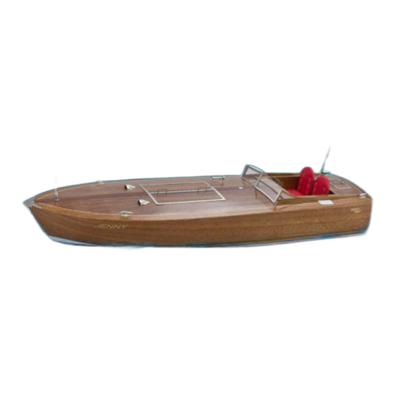
- Page 1 Order no. 3055/00 Building instructions in English can be downloaded from our website: www.aero-naut.com Vous pouvez télécharger la notice de construction à parti de notre site web: www.aero-naut.fr...
- Page 2 Introduction: The model should be assembled following the sequence of the stages of construction described in these instructions. The laser-cut components are individually numbered. The manufacturing process leaves some incomplete cuts as well as small tabs which have to be cut away using a thin-bladed modelling knife. The dark edges of the laser-cut parts should also be rubbed off using abrasive paper to ensure that glued joints are sound.
- Page 3 Glue parts 13 and 14 to frame 1. Glue the doublers 15 on both sides of the aft keel 12; the slots in parts 15 must be on the underside, and line up correctly with those in part 12. The darker recessed areas of parts 15 form a channel, and must be on the inside.
- Page 4 Push the RC plate 29 into the notches in frame 1, but do not glue it in place. Insert the RC plate support 29a in the slot in frame 1 and glue it to frame 1 only, i.e. not to the RC plate 29. You will find notches at the front end of the forward keel 11, and in frames 9 and 10, which accept the hull stringers: use a flat file to bevel...
- Page 5 Glue the hull bottom reinforcements 22 to frame 1. Glue the side reinforcements 23 to frame 1. Sand back the excess length of the stringers 19, 20 + 21 at the stern until they are flush with the reinforcements 22 + 23. Glue the plywood transom 24 to the outside of the stern, butting up against parts 14, 22 and 23.
- Page 6 Bevel the bottom edge of the hull bottom panels 25 using a sandpaper block. Lay the joined panels on the Lay the bottom panels 25 flat on hull framework and clamp the bench, and tape them together them in place temporarily. as shown.
- Page 7 To avoid patches of glue showing up on the finished model, the mahogany face of the hull sides 27 should be given at least two coats of sanding sealer, sanding between coats. Locate the inside face (light-coloured wood) of both hull sides, and use a sanding block to taper them at the bow end at an angle of about 30°.
- Page 8 Carefully sand away the excess hull side material where it projects. Glue the mahogany transom 28 to the hull. Carefully sand back the projecting edges flush with the hull sides. The hull can now be removed from the jig. Bend the support tabs to and fro to break them away from the top of the frames.
- Page 9 Glue the rudder bush 61 in the channel in the keel, leaving the bottom end of the bush projecting by about 2 mm from the bottom panels. Glue the rudder bush to the RC plate support 29a using cyano-acrylate. Make sure there is no excess glue at the top! Slide the RC plate back towards the stern and fit the two retaining screws 121.
- Page 10 Apply sanding sealer to one face of the deck 43 and the deck edging pieces 48; this face later forms the top of the deck. Allow the sealer to dry out, then apply adhesive tape to the outside edges of the deck 43, leaving half its width projecting.
- Page 11 Glue the hatch frame The next step is to form the rear hatch components 52 - 54 together, cover into the correct shape: for this with 52M in the centre. A ring- you require the template 117, four pan- screw has to be fitted to the head screws (such as servo retaining centre part to retain a rubber screws) and a scrap piece of 2 x 4 mm...
- Page 12 113 to the instrument panel immediately to the right of the steering column. The name placard Jenny 106 can be stuck either to the instrument panel or the cockpit top cover. Assemble the throttle control from the three mahogany parts 76, the etched parts 102 + 103 and the nickel-silver lever 76a.
- Page 13 Glue the side window frames 71 in the slots in the deck. Mask off the upper part of the hull, which is to remain as varnished mahogany. Paint the underwater hull white, as shown in the drawing. Mask off the white waterline as shown in the drawing, then paint the underwater hull red before removing the masking tape.
- Page 14 Bend the forward flagstock 100 double along the centreline, and glue it to the deck together with the flange 101. Mask off the deck around the motor and rudder hatches with strips of adhesive tape, and place the hatches in the hull.
- Page 15 Screw the propeller onto the stern shaft, and tighten it against the locknut. Slip the rudder / shaft assembly 60 into the rudder bush. Open the rudder hatch and remove the two screws which retain the RC plate. Slide the RC plate forward under the cockpit opening. The rectangular aperture in the plate is designed for a standard servo.
- Page 16 Part no. Description Dimensions Material No. Off Hull frame 3 mm birch plywood Laser-cut Hull frame 3 mm birch plywood Laser-cut Hull frame 3 mm birch plywood Laser-cut Hull frame 3 mm birch plywood Laser-cut Hull frame 3 mm birch plywood Laser-cut Hull frame 3 mm birch plywood...
- Page 17 Etched nickel-silver Side throttle lever Etched nickel-silver Upper throttle lever Etched nickel-silver Instrument bezel Etched nickel-silver Steering wheel bezel Etched nickel-silver Jenny name placard Etched nickel-silver Step Etched nickel-silver Fueltank cap Etched nickel-silver Windscreen frame Etched nickel-silver Windscreen bezel Etched nickel-silver...
Need help?
Do you have a question about the JENNY and is the answer not in the manual?
Questions and answers