
Related Manuals for aero-naut Queen


Summary of Contents for aero-naut Queen
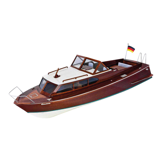
- Page 1 Queen Order No. 3080/00 Building instructions in English can be downloaded from our website: www.aero-naut.com Vous pouvez télécharger la notice de construction à parti de notre site web: www.aero-naut.fr...
- Page 2 0 at the bow; note that the keel 12 must end flush with the top of the frames. Frame 7 supports the motor (see Stage 22), and therefore must be fitted at an angle. aero-naut Modellbau GmbH & Co. KG, Stuttgarter Str. 18, D-72762 Reutlingen...
- Page 3 Insert the two fore-and-aft bearers 13 in the slots in frames 1 and 3 - 7, and press them fully into the notches; note that the bearers 13 must not project. Press frame 1 against the bearers 13 from the rear. Position the plywood template 18 between frames 3 + 4 to ensure that the whole structure is “square”.
- Page 4 Glue together the front end of the three chine stringers 19 over a length of 150 mm. Trim the joined stringers to fit neatly against the keel 12, and offer them up to the keel 12 and frame 11. Use a sanding block to sand back the stringers 19 so that they do not project beyond the front edge of the keel 12 at the sides and forward.
- Page 5 The next step is to trim the side stringers 20 + 21 to fit against the keel 12 and glue them in place. Press the strips into the notches in frame 11. When the glue has set hard, glue the stringers 20 in the notches in frames 1 - 11.
- Page 6 Apply more glue to the joints between the side panels 23 and the frames and stringers from the inside of the hull. Caution: take care to identify the left and right sides during the next stage. Chamfer the inside (centreline) edge of both hull bottom panels 24 (see arrows), to produce a sharp edge on the outside of the joint.
- Page 7 Caution ! Kielteile The next three stages, which are described on this page, must be carried out while the glue is still soft. This means that there is little time for adjustment, so please check once more that the bottom panels 24 are an accurate fit before reaching for the glue.
- Page 8 The boatstand can now be assembled: glue parts 27, 28 and 29 together in pairs, and glue these assemblies to the bearers 29 when the glue is dry. The finished boatstand. From this point on the hull should be left in the stand for all construction work.
- Page 9 Glue the keel wedge 31 between the hull bottom 24 and the shaft tube 30. Ensure that the propeller is still free to rotate. Glue the deck support rails 22 in the notches in the top of frames 1 - 11, and secure them with screw- clamps: press the rails 22 outwards as far as they will go, i.e.
- Page 10 Glue the transom 25 to the outside of frame 1. Fit the superstructure side walls 35 in the deck 32. The deck support rails 22 must lie flush with the deck; you may need to sand them back slightly to achieve this.
- Page 11 Lay the cockpit floor 38 between the cockpit side panels 39, resting on the battery support rails 74, and push it against the half-frames 6 as far as it will go. Fit the rear cabin wall 40 on the cockpit floor 38 and press it fully against the half-frames 6.
- Page 12 If necessary, adjust the opening in the servo plate 73 to suit your rudder servo. Glue the bush 49 for the rudder shaft 70 and the rudder support plate 73 in the hull, using two- pack adhesive for the bush. Assemble the rudder from parts 70 to 72.
- Page 13 The next step is to build the cabin roof: fix the fore-and-aft roof bearers 51 to the superstructure side walls 35 using spring clamps, keeping them exactly flush at the top. These rails should be precisely 310 mm long, and must be fitted as far forward as possible.
- Page 14 Parts 55 to 59 should be painted at this stage. Glue the prepared handrails 55 in the holes in the roof 52, and assemble the aerial from parts 57 - 59. Working lamps can be installed in the form of 5 mm Ø LEDs (not included in the kit); alternatively wooden dummy lamps can be fitted.
- Page 15 Glue a 20 mm length of 1.5 Ø rod into the steering wheel 93, insert it in the console 44 and the cabin wall 40 and glue the parts together. Stick the 'Queen' placard to the cabin wall. The armrest supports are formed from the 1.5 mm Ø...
- Page 16 Glue parts 82 to the side panels 39 to form the ends of the bench seat base. Glue the front panel 83 to parts 82 with the edges flush; there should be a gap about 1 mm wide at the bottom, so that any water which gets inside the seat can escape again.
- Page 17 The flagstock is made from a 140 mm length of 2.5 mm Ø metal rod: lay the rod in the template, and solder the small ring and the German silver cleat to it. Assemble the flagstock truck from parts 84 + 84.1, glue it to the tip of the flagstock, then paint the finished 84 + 84.1 unit.
- Page 18 Cut the 1.5 mm Ø whip aerial to a length of 80 mm and glue it to the aerial assembly as shown. Cut out the pennant, fold it over, glue the halves together and finish it with waterproof lacquer. Drill holes for the cleats 94 and glue them in place.
- Page 19 Part No. D escription Material No. Off Size Depron 3 mm, die-cut Hull frame Plywood 3 mm Hull frame Mahogany plywood 1.5 mm Frame doubler Plywood 2 mm Hull frame Plywood 3 mm Hull frame Plywood 3 mm Hull frame Plywood 3 mm Half-frame...
- Page 20 Part No. D escription Material No. Off Size 51 Roof fore-and-aft bearer Spruce strip 3 x 3 x 310 mm 52 Roof Plywood 1 mm 53 Side window Mahogany plywood 1.5 mm 54 Front window Mahogany plywood 1.5 mm 55 Handrail Mahogany plywood 1.5 mm 56 Aerial bearer plate 1...
- Page 21 84.1...
- Page 22 10.1...
Need help?
Do you have a question about the Queen and is the answer not in the manual?
Questions and answers