Advertisement
Quick Links
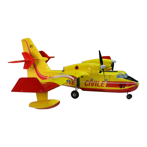
Building Instructions
Canadair CL-415
electric-powered RC
model aircraft
Order No. 1343/00
Specification:
Wingspan
Length
Wing area
Tailplane area
Total surface area
All-up weight incl. 12 Panasonic EX cells
Area loading (wing only)
Total surface area loading
RC functions:
Elevator
Ailerons
Rudder
Throttle
Landing flaps (optional)
„aero-naut" Modellbau
Stuttgarterstr. 18-22
D-72766 Reutlingen
http://www.aero-naut.de
© by „aero-naut" Modellbau
Canadair CL-415
approx. 1505 mm
approx. 1043 mm
approx. 31.6 dm²
approx. 7.98 dm²
approx. 39.58 dm²
approx. 2450 g
approx. 77.5 g/dm²
approx. 61.9 g/dm²
Replacement parts:
GRP fuselage
GRP motor nacelle
1343/02
1343/03
1
Advertisement

Related Manuals for aero-naut Canadair CL-415


Summary of Contents for aero-naut Canadair CL-415
-
Page 1: Building Instructions
Area loading (wing only) approx. 77.5 g/dm² Total surface area loading approx. 61.9 g/dm² RC functions: Replacement parts: Elevator GRP fuselage 1343/02 Ailerons GRP motor nacelle 1343/03 Rudder Throttle Landing flaps (optional) „aero-naut“ Modellbau Stuttgarterstr. 18-22 D-72766 Reutlingen http://www.aero-naut.de © by „aero-naut“ Modellbau... - Page 2 Canadair CL-415 10-cell power system: 1.) Race 400 / 6.0 V with gearbox 2.64 : 1 7121/06 with propeller 8.5 x 6 7229/28 12-cell power system: 1.) Race 400 / 6.0 V with gearbox 2.64 : 1 7121/06 3.00 : 1...
- Page 3 Canadair CL-415 Glued joints: selecting the correct adhesive can save a significant amount of weight. Use cyano-acrylate glue (“cyano”) wherever possible, either thin or thick as appropriate; the thin type penetrates into the wood grain and stiffens it considerably. You can often simply hold balsa parts together and tack-glue them with cyano.
- Page 4 Canadair CL-415 (61) to the main spar by running thin cyano along the joint. Slide a tapered-section balsa strip under the front edge of the leading edge sheeting (61), as shown in section F-F, so that it is pushed up against the ribs;...
-
Page 5: Half-Former
Canadair CL-415 Relieve the floats (78) to accept the pylons, and push them onto the float ribs (77). Check that everything fits correctly, then glue these parts together. Glue the second float shell in place using Stabilit-Express. Work carefully here, as the floats must, of course, be watertight! Fig. 10. - Page 6 Canadair CL-415 and slip the snakes into place. Fit the steel pushrods (26) from the rear, and fit them in the appropriate sleeve (25). Now slide the support plate (95) and snakes slowly into the fuselage, allowing the wires to guide the snakes to and through the appropriate exit slots.
-
Page 7: Spacer
Canadair CL-415 Three aluminium hinge lugs (38) are used as the basis of the rudder hinge system. Drill the 2 mm Ø holes and remove all rough edges. Cut down the lugs (38) approximately as shown on the plan. Roughen the surface of the metal lugs as follows: place the lug on a hard surface, lay a coarse, sharp file on it, and roll it to and fro - job done. - Page 8 Canadair CL-415 Fix the nacelles to the wing using three M4 x 30 mm screws each (you did remember to route the motor cables out of the wing, didn’t you?), and run thin cyano all round the periphery (and also to the screws inside the nacelles);...
- Page 9 Canadair CL-415 remainder from a greater range. Allow the first coat of paint to dry slightly, then apply a second coat to achieve even coverage. Once the paint is dry remove the masking tape and paper etc. Remove all adhesive residues carefully.
- Page 10 We hope you have many pleasant flights with your new model, and wish you as many happy landings as take-offs. aero-naut Modellbau Parts List - Canadair CL-415 Part Description Material Size in mm...
- Page 11 Canadair CL-415 Part Description Material Size in mm Tailplane trailing edge sheeting Balsa 65 x 1.5 mm, as plan Tailplane false leading edge Balsa 7 x 3 mm, as plan Tailplane leading edge sheeting Balsa 37 x 1.5 mm, as plan...
-
Page 12: Wheel Axle
Order No. 7639/21 laminating resin) Pattex gel cyano Order No. 7639/25 Soft binding wire, hinge tape Plan text - Canadair CL-415 View D View G Aluminium strap, 37 x 8 x 1.5 mm Cut openings with fretsaw or similar Schematic view only of parts (11) and (12) -
Page 13: T-Piece
Canadair CL-415 M2 screw and nut Solder washer (wheel retainer) Axis of finlets offset approx. 2° right Tailplane structure before elevators are separated Aluminium strap, 10 x 1 x 130 mm Section B-B Edge of decal Glue receiver aerial guide sleeve (20) to the fuselage side Centre of Gravity (C.G.) 70 - 85 mm...
Need help?
Do you have a question about the Canadair CL-415 and is the answer not in the manual?
Questions and answers