Advertisement
Quick Links
Advertisement

Subscribe to Our Youtube Channel
Related Manuals for aero-naut SkyMAXX


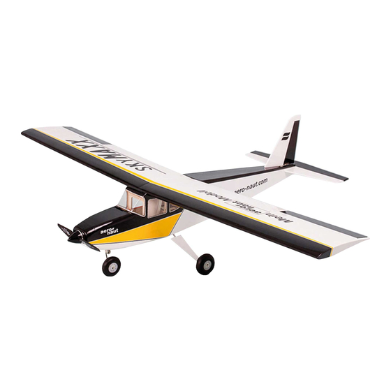
Summary of Contents for aero-naut SkyMAXX
- Page 1 aero naut MAXX Order No. 1370/00 RC Trainer...
- Page 2 SkyMAXX Tips & Notes SkyMAXX is a sturdy trainer for 3 channel RC with a scale-like apperance. Take-off is easy with its tricycle undercarriage and big wheels from any flying field with short grass. All parts, with the exception of stripwood, are precisely laser-cut and allow for a rapid building Attention! Read instructions process.
- Page 3 Fuselage For electric power glue former E-1A to former E-1B and glue together formers E- 2. Make sure that contours of formers match perfectly. Secure with clamps until glue has completely dried. E-1B E-1A For IC power glue formers V-1 together as well as formers V-2. Make sure that contours of formers match perfectly.
- Page 4 R-6-1 Glue reinforcement R-6-1 to the rear of former R-6. Make sure that holes for wing dowels match perfectly. A small step will result on the top to accommodate the wing. Temporarily insert wing dowels F-33 into holes for correct position, secure parts with clamps and remove wing dowels. Note: Top contour of R-6-1 is angled for dihedral.
- Page 5 Temporarily insert formers E-2/V-2 (depending on version) and R-7 into slots of fuselage side for correct alignment. Weigh down parts with suitable weights and remove formers. Leave to dry. E-2 / V-2 Build up the left fuselage side accordingly.
- Page 6 R-13-1 Glue reinforcement R-13-1 to the underside of servo tray R-13. Insert formers R-5, R-6, R-7 and R-8 and servo tray R-13 into right fuselage side. R-13 Do not glue! Glue two landing gear brackets R-14 together and then glue over respective cut-out in doubler of right fuselage side behind R-7.
- Page 7 Glue landing gear brackets R-14 in place on left fuselage side. Temporarily position former R-7 and landing gear retainer R-15 in left fuselage side for correct alignment. Glue wing retainers R-16 together and insert into notch in R-16 R-16 right fuselage side. Also insert landing gear retainer R-15 into brackets R-14.
- Page 8 Insert former R-4 into right fuselage side. Do not glue! Place left fuselage side on formers and carefully align with tabs. Check for proper fit, then apply glue to formers, landing gear R-15 and wing retainer R-16 and glue left fuselage side in place. Secure until glue has dried.
- Page 9 Cut to length 8 ×8 mm triangular stock R-17 and glue in place on fuselage sides. Secure with pins until glue has dried. R-17 Tip: To follow the outline of curved fuselage sides more easily, saw small cuts along the inside of triangular stock. R-17 R-17 R-17...
- Page 10 R-10 Glue formers R-9 to R-12 inplace and secure with clamps and tape. Make sure mrkings on R-12 face aft. R-11 R-12 Check fuselage for symmetry! Attention: Holes for rudder control in formers R-9 and R-10 must be on left fuselage side! Again check contact surfaces of fuselage sides and triangular stock, then glue fueselage top R-18 and fuselage bottom R-19 in place and secure with clamps and tape.
- Page 11 Glue in place fueselage bottom sheeting R-20 and make sure slot for landing gear faces aft. Secure with tape. R-20 Glue retaining brackets R-21 to rear of instrument panel R-22, then glue assembly in place on former R-8. Glue cockpit roof R-23 into slots in former R-6. R-23 R-22 R-21...
-
Page 12: Electric Power
IC Power: Before you glue former V-2 in place, drill holes for motor mount, throttle control linkage and fuel line. The crankshaft position is indicated on the former. If motor mount provides notches for nose wheel gear, holes for included plastic nose gear bracket do not apply. - Page 13 In the following building step use E-3 for electric power and V-3 for IC power. Carefully bevel curve at rear of E-3 and V-3 to the front and to the bottom. This is where the front cockpit glazing will be inserted in the slot between instrument panel and E-3/V-3.
- Page 14 Carefully sand fuselage and round off the edges with special attention to the nose section. Use E-4/V-4 for symmetry at the front end. Also pay special attention to get a smooth transition from fuselage side to top sheeting E-3/V-3. Glue two or three rectangular pieces of balsa scrapwood to cabin roof R-23 (for example excess wing sheeting material) and sand to shape.
- Page 15 Use a modeller‘s knife and a razor saw to cut out the top of the cowling and remove from fuselage. Sand contact surfaces to a smooth finish. Glue parts R-26 and R-27 together, then epoxy magnet R-28 R-28 into bracket. Slide tab R-29 into slot of top sheeting and glue in place.
- Page 16 Glue bracket R-30 to underside of hatch cover. Make sure to centre R-30 at rear end. Then epoxy magnet R-28 into bracket. Attention: Make sure to check polarity of magnets before you glue! Slide tab R-31 into slot of hatch cover and glue in place. Using R-28 short slot, slide locator R-32 onto tab and glue.
- Page 17 Tail unit Place stabilizer R-39 and elevator R-40 on an even building board and glue in place sheeting material R-41 and R-42. Secure with suitable weights until glue has dried. R-42 R-41 R-40 R-39 Turn parts of tail unit upside down and glue sheeting material R-41 and R-42 to unserside of tail unit.
- Page 18 Bevel front edge of elevator for sufficient control throw. Then glue in place control horn R-43 in slot on underside of elevator. R-43 Round off contours of stabilizer and elevator. Place fin R-44 and rudder R-45 on an even building board and glue in place sheeting material R-46 and R-47.
- Page 19 Turn parts of tail unit upside down and glue sheeting material R-46 and R-47 to opposite side of tail unit. Secure with suitable weights until glue has dried. R-46 R-47 Bevel front edge of rudder for sufficient control throw. Then glue in place control horn R-43 in slot on left side of rudder.
- Page 20 Drill former R-12 with 3 mm at indicated position then use file to create slot. R-12 Slide snake outers R-48 for elevator and rudder through respective holes in formers and out of fuselage. Use a file to create suitable angle for rudder snake outer exit in R-48.
- Page 21 Push elevator snake back into fuselage until clevis is at position in former R-12 shown on picture. Clevis must be free to move in former R-12. Make sure there is some vertical play, too. If necessary, use file to enlarge opening for clevis. Epoxy snake outers to formers.
- Page 22 Wings Note: The following instruction describe construction of the right wing half. The left wing half is buildt accordingly. Just turn the depron jig upside down. Insert light-ply wing spar F-1 and light-ply ribs F-2 to F-5 into jig H-0 and glue together. Please note that root rib F-2 is angled a little because of the wing dihedral angle.
- Page 23 ... than insert five balsa ribs F-7 and two balsa ribs F-8 into jig and glue to wing spar. Make sure to place ribs F-8 correctly. Ribs F-8 define position of aileron servo bay. Glue in place top spars F-9 (3×8 mm spruce) and F-10 (3×5 mm spruce). Lightly sand surface of brass tube F-11 and install in front hole of light-ply ribs.
- Page 24 Glue in place upper wing sheeting F-12-R/L and F-13 flush with root rib. Make sure to place outline of ailerons correctly! Tip: Use available stripwood to hold down sheeting material at position of spars and evenly secure sheeting material with clamps. Secure opposite end of sheeting material with pins and tape.
- Page 25 Glue in place bottom spars F-9 (3×8 mm spruce) and F-10 (3×5 mm spruce). Install aileron leading edge F-15 together with aileron end rib F-16 in corresponding notches in ribs and glue in place. F-33 Glue in place servo frame F-17 on ribs F-8. Glue in place wing dowel brackets F-18 and F-18 F-19 to front of ribs and and to back of wing spars, respectively, between ribs F-2/F-3.
- Page 26 Slightly bevel rear edge of top sheeting to establish a good contact surface for gluing. Fit in place bottom sheeting panels F-23 and F-24 and glue in place flush with root rib. Route servo lead through holes in ribs and secure in servo bay with tape. Fit bottom root sheeting F-14-1 and F-14 in place and glue.
- Page 27 With a pencil draw line of aileron cut-out to end of wing tip, then cut out aileron with a razor saw. Sand ribs and sheeting material flush with spruce spars. Glue in place web F-32 and sand flush with top and bottom sheeting. F-32 Cut off excess material at aileron leading edge and sand flush with leading edge.
- Page 28 Install servo tary F-25. Note that opening for servo horn faces wing tip. With a soft pencil draw a line from centre of opening to aileron, then drill 7 mm from aileron leading edge with 5 Attention: Drill vertical through bottom sheeting of aileron! F-25 F-35...
-
Page 29: Completing The Model
Completing the model Join the left and right wing halves with wing joiner F-38 and fit into fuselage. Use a file to correct holes for wing dowels in former R-6, if necessary. Place template F-39 (arrow pointing forward) on wing flush with rear end of trailing edge and drill through wing and into wing retainer R-16 with 5 mm. - Page 30 Note: For clarity the model is shown without covering material in the following building steps. Attach rudder and elevator with hinge Glue fin into fuselage. Make sure tabs at the bottom of fin rest in tape or other high-quality tape. respective cut-outs of formers.
- Page 31 Assemble nose leg from parts R-57 to R-62 as shown. R-57 First install bearing plate R-58 des Fahrwerks to back of former E-2 using parts R-54 to R-56. R-60 Tip: Insert screwdriver through opening in front formers for easy installation. From below insert nose leg in fuselage and into bearing plate, using wheel collars R-59 and set screw R-60 to secure nose leg in bearing plate.
- Page 32 Angle front end of push rod R-68 as shown, install clevis R-52 on push rod and connect to nose leg control horn. Note: Picture shows snake outer for throttle control (IC power) as well. May be omitted for electric power. R-68 R-52 Install servos in servo tray, cut to length snake inners and push rod...
- Page 33 Slightly angle battery tray R-38, install in fuselage and glue to formers. Notches on either side of battery tray lock into formers R-5, R-6 and R7. R-38 Note: Battery tray ends at former R-7. We recommend to colour with a felt-tip pen or paint the inside of the window frames. Fit side window panes R-69 and R-70 in place and secure with a few drops of glue.
-
Page 34: Final Adjustments
First flight The tricycle landing is ideal for ROG. However, if a suitable flying field is not available, a helper can easily hand-start the SkyMAXX. Bring the model up to a safe hight and get used to the controls and the model‘s reactions. The recommended control throws are safe basis, which can be modified to your requirements. -
Page 35: Parts List
Parts list Description Pcs. Material Sheet Type Dimensions Description Pcs. Material Sheet Type Dimensions wing jig depron laser-cut 3 mm R-55 washer metal ready made ID 3.2 mm E-1A former (electric power) birch ply laser-cut 3 mm R-56 stop nut metal ready made E-1B... - Page 36 Also from the aero-naut range of models: Triple Speed, R.E.S., Thermic 3-in-1 model: 1 fuselage - 3 different wings wingspan 1,780, 1,990, 2,550 mm laser-cut wood kits Luscombe Silvaire 8 wingspan 1,600 mm laser-cut wood kit complete with landing gear...
Need help?
Do you have a question about the SkyMAXX and is the answer not in the manual?
Questions and answers