Advertisement
Quick Links
Advertisement

Related Manuals for aero-naut Foxx


Summary of Contents for aero-naut Foxx
- Page 1 aero aero naut naut Order No. 1351/00...
-
Page 2: Tips And Hints
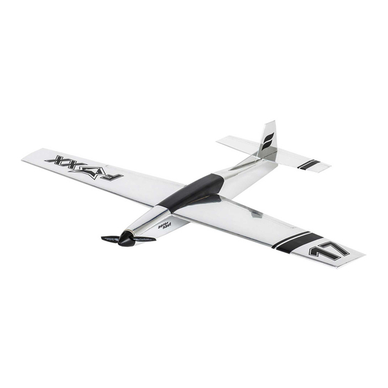
FOXX is a powerful pylon racer. Building materials are mostly balsa and light-ply to achieve a light yet strong structure for maximum flying performance. Due to its considerable top speed this model is recommended for experienced pilots only. We use mostly laser-cut parts for maximum precision and to speed up the building process. - Page 3 Protect your building board with cling film and position right fuselage side R 1 on building board. Attention: The fine lines indicating the position of R 10 the canopy need to be visible on the outside of the fuselage! Glue in place wing support R 10 together with formers R 4 and R 5.
- Page 4 R 8/9 Chamfer lower edge of former R 6 to match installed positon behind former R 5 and temporarily insert in slots in right fuselage side behind R 5. Glue R 9 at an angle of 90° to servo tray R 8. Temporarily insert R 8/R 9 in slots in rigth fuselage side below R 6.
- Page 5 Sand triangular stock at rear end of fuselage so that fuselage sides meet. Apply glue to R 6, R 8/R 9 and to contact surfaces of triangular stock, draw fuselage sides together and secure with clamps and/or pins until glue has dried.
- Page 6 12 mm from the top drill rear end of fuselage with 2 mm for elevator control. Insert snake inner R 19 through rear end of fuselage and through horizontal slot in former R 9. Apply glue to pushrod housing at rear end of fuselage only and cut off flush with fuselage.
- Page 7 R 20 Carefully sand top and bottom contact surfaces of fuselage, then sheet top and bottom of fuselage with R 20 (3 mm balsa), grain crosswise. Attention: Do not sheet contact surface of tailplane! R 20 Sand front of fuselage flush with R 3 (A or B) and glue in place R 11 A or R 11 B (1 mm birch ply), depending on type of motor.
- Page 8 cut here Carefully sand fuselage and round off the edges. With a razor saw cut out canopy along the lines indicated on fuselage sides. cut here Glue together fin parts R 14 and R 15. R 16 is added to fin after model has been covered.
- Page 9 R 17 Bevel off front edge of elevator R 13 to allow for sufficient control throw, then glue in place control horn R 17. Attention: Note orientation of control R 13 horn. The vertical edge faces aft! When dry, sand front edge of control horn flush with front edge of elevator.
- Page 10 Fit together the two-piece wing jig and secure to building board with tape. Glue together two centre ribs F 1. Then insert ribs F 1 to F 10 into jig. If necessary, tack-glue tabs to building bord with a drop of glue to secure ribs. F 10...
- Page 11 F 12 F 11 Glue in place upper wing spar 11 (5×2 mm spruce). Make sure all ribs are upright and fully seated in jig. Glue leading edges F 12 (4×4 mm obechi) to front of ribs. Insert pins in front of leading edes into jig to hold leading edges in position.
- Page 12 Glue in place top wing sheeting panels F 13 and F 14 (1.5 mm balsa). Fit and glue in place F 13 first. F 13 Attention: The rear end of F 13 must coincide with centre line of wing spar. Remove residual glue immediately to provide a good contact surface for F 14.
- Page 13 Fit and glue in place webs V 1 to V 3 between ribs F 1 to F 4. Glue in place lower wing spar F 11 (5×2 mm spruce). F 11 Glue servo trays F 15 in rib bays between ribs F 3 and F 4 to upper spruce spar and to top sheeting.
- Page 14 F 17 Carefully sand rear edge of wings flush with ribs. Trial-fit trailing edges F 16 and cut contact surfaces at wing centre to appropriate angle. Then glue trailing edges in place and secure with tape. Carefully sand top and bottom wing sheeting flush with end ribs.
- Page 15 Position wing on fuselage and align centre lines of wing and fuselage. Drill with 4 mm through wing and R 7 for M4 wing bolt F 19. Redrill R 7 with 5 mm. From below insert nut R 24 in R 7 and glue in place with epoxy.
- Page 16 With soft pencil mark ailerons on trailing edge: aileron cut-outs start 50 mm from centre line of wing. They are 210 mm long and 18 mm deep. Cut out ailerons with modeller´s knife and razor saw. F 20 Bevel off front edge of ailerons to provide for sufficient control throw.
- Page 17 48 - 50 mm behind the leading edge, marked on the fuselage side. The wing incidence is 0°. Control throws for elevator are +/- 5 mm, for ailerons +/- 4 mm. Have fun with your new FOXX! 48 - 50 mm...
- Page 18 Item Pieces Material Laserplatte Type Dimensions balsa laser cut 3 mm right fuselage side balsa laser cut 3 mm left fuselage side R 3 A light ply laser cut 3 mm motor mount (inrunner) R 3 B light ply laser cut 3 mm motor mount (outrunner) light ply...
- Page 19 Item Pieces Material Laserplatte Type Dimensions F 1 - F 10 rib je 2 balsa laser cut 2 mm F 1 A balsa laser cut 2 mm riblet 5 × 2 × 770 mm F 11 spruce cut part wing spar F 12 obechi cut part...
- Page 20 More great kits from our range... Triple speed 1128/00 Triple R.E.S. 1128/01 Triple thermic 1128/02 aero Luscombe Silvaire 1369/00 naut Lasercut kit aero-naut Modellbau Stuttgarter Strasse 18-22 D-72766 Reutlingen and many more at www.aero-naut.com www.aero-naut.de...
Need help?
Do you have a question about the Foxx and is the answer not in the manual?
Questions and answers