Table of Contents
Advertisement
Quick Links
Advertisement
Table of Contents

Related Manuals for aero-naut Jonny


Summary of Contents for aero-naut Jonny
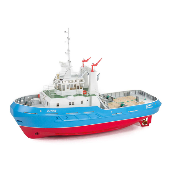
- Page 1 Harbour tug Jonny Order No. 3030/00...
- Page 2 Harbour tug Jonny Jonny is a fully operational model which will give great pleasure to any model builder. The basic design is that of a modern harbour tug. One outstanding feature of the kit is the very high quality of the materials supplied, and the reward is a superb model. The capacious hull is moulded in GRP, and all locations for openings are moulded-in.
- Page 3 Assemble parts 1 - 4 to make the boatstand. Hull Use a pencil to pick out the marked position of the bow thruster (BSR); this will help when cutting the openings. Mark the openings for the bow thruster to suit the unit you intend to install, and cut them out.
- Page 4 Angle the deck supports 21 at a point 38 mm aft of frame 9, and glue them 21/20 to the frames. Rub glue into the underside of the cracks. Anchor hawse pockets Open up the hawse openings in the hull at the marked points. Glue the hawse pockets 6 together, then temporarily tape them in the openings.
- Page 5 Saw a 2 mm wide lengthwise slot in the skeg tube 37. Glue together the skeg components 35 - 34 - 35, keeping the parts flush at the rear; this produces a channel at the front. Bend the brass rod 36 to the shape shown, and glue it to the skeg using Stabilit / Acrylit.
- Page 6 Steps 17 and 18 describe the installation of the stern roller. If you don't wish to install the system, please continue with Step 19. Stern roller The parts of the stern roller should be glued together as shown in the drawing.
- Page 7 spring clips Wedges 61 Allow the glued joints to set hard, then remove the main deck and apply adhesive (Stabilit or Acrylit) to the top edge of the frames. Place the deck in position again, and secure it using the wedges and rulers or other long strips. Use spring clips to press the deck onto the deck supports as shown.
- Page 8 Dowel The deckhouse is now used as an aid in installing the coaming in the foredeck. Adhesive tape Separate the coaming 87 and remove any rough edges. Place the coaming on the foredeck girder 23, press it against the foredeck and secure it with a strip of tape. Push the coaming into the corner with a piece of dowel of around 10 mm Ø, and bend the radius to fit snugly.
- Page 9 Insert the supports 91 in the foredeck. Separate the bulwark reinforcement 90 and the bow reinforcement 89. Fit the bow reinforcement 89 on the supports 91. Cut the two bollard tubes 94 to length and fit them through the bow reinforcement and into the deck to aid alignment. The centre part of the reinforcement 90 can now be fitted;...
- Page 10 Assemble the foredeck emergency exit by gluing together parts 99 - 103. Two switches with 6 mm shafts can be installed in the floor 99, e.g. for activating the model batteries. Glue the hinge components 104 to the cover 105. Bend the handle 106 to the shape shown, and glue it in place.
- Page 11 Complete the connecting wall 108 by fitting the doors 109. Glue this assembly in the wall 82. Complete the rear superstructure wall 110 with the doors 111, and glue it to the floor 65 and the wall 108. The outer wall 113 of the exhaust pillar fits in the same slot from the rear.
- Page 12 Installing the glazing panels Don't remove the tabs in the sides of the glazing panels, as they help to align the panels. Remove the protective film from one face of the glazing panel, leaving the other in place. Apply a small amount of adhesive to the back of the window frame (etched part). Place the panel in position centrally, leaving a recess all round;...
- Page 13 1 Bottom section 2 Brass tube, 3.0 / 2.1 x 12 mm 3 Top section 4 Monitor column 5 Brass tube, 4.0 / 3.1 x 100 mm 6 Base 7 Spindle bridge 8 Handwheel, laser-cut 9 Jet nozzle 10 Spray nozzle A good method of swivelling the monitors is to fit pulleys on the brass tube and drive them from a servo using rubber bands.
- Page 14 Wheelhouse Separate the lower mounting frame 141. Separate the lower wheelhouse walls by removing the tabs at the joint positions. Tape the parts together and insert them in the mounting frame before gluing the joints on the inside. The floor 150 can be inserted to stiffen the structure, but do not glue it to the walls at this stage. Tape the window frames 146 - 149 together, and insert them in the upper mounting frame 151;...
- Page 15 When all the glued joints have dried fully, the door frame components 168 and 169 can be glued in the wheelhouse. Glue the wall 170 to the frame and the lower wall from the inside. Glue the door 171 in the door opening. Tape together the lower part of the wheelhouse and the roof section.
- Page 16 Mast Assemble the mast base as shown in the drawing at the bottom. Part 174 (left) is not shown in the interests of clarity. Glue parts 178 to the tubular mast. Fit the piston 181 through the cylinder 180, and glue parts 182 and 183 to the ends as shown.
- Page 17 Soldering It is important to use an iron of adequate rating for soldering the railings. We recommend at least a 48 W tool. A high temperature should also be set in order to avoid overheating the parts. This approach delivers a large quantity of heat at the joint position in the shortest time, and helps the solder to flow well.
- Page 18 The superstructure railing Railing between the exhaust pillars: Thread five railing stanchions onto the handrail and lower rail, and insert them in the deck. You can either glue these parts together using cyano, or solder the joints. Paint the railing and glue it in the deck. The lamp bracket for the stern and towing lights is made from parts 209 - 211.
- Page 19 The next step is to assemble the monitor platform railing. Left-hand side: Thread the handrail and the upper middle rail through the companionway stanchions. Insert the first stanchion in the platform, and bend the handrail and the lower rail so that they fit in the holes in the stanchion.
- Page 20 Searchlight The searchlight is located in a separate frame on the etched parts sheet. Always bend the sheet material towards the etched-in groove to avoid the parts breaking. First bend the two sides of the box 215 upwards through 90°. Insert the two side panels 216 in the notches in the bottom.
- Page 21 Glue the backplate 225 to the housing 223. Glue the handles 226 in the holes. Glue the latches 227 in the holes above the housing. The searchlight can now be painted. Cut the LED pins to length and solder the wires to them. Insulate the soldered joints and pins with heat-shrink sleeves or similar.
- Page 22 Three braking systems are required. Carefully separate the brake discs 257 from the brake plates 256 and glue them together. Sand the engraved part numbers smooth. Sand the brake discs and the insides of the brake so that they are smooth and rotate freely.
- Page 23 Withdraw the shaft. Insert all the individual parts in the winch body as shown in the drawing alongside. Push the shaft right through. Assemble the parts of the capstan head 267 and sand the assembly before gluing it to the shaft. Glue the pins 270 in the retaining plate 269, and fit the levers 262 / 263.
- Page 24 In the area between the central and right-hand spacer rails the base plates should be sanded at an angle as shown. Glue the tubular guard 278 in place. Glue the reinforcements 281 centrally to the frame 279; these parts are laser-cut in the correct sequence in laser-cut sheet 2. Start with the “bottom”...
- Page 25 Cable guide system Glue the side plates 301 to the base plate 300. Glue the guide bushes 299 and the upper cover plate 302 between them as shown. Glue the two cable guides 303 in the box. Glue the guide plate 304 at the bottom.
- Page 26 Assembling the winch Glue the four brake units to the bearing brackets 284, aligning them as shown in the drawing. Fit the shafts 296 through the drums. Glue the left and right frame assemblies to the base plate. Connect the motor and coupling (if fitted). The whole assembly can now be painted.
- Page 27 Lay parts 335 down flat, and push part 336 into them. Glue the bearing plates 337 in place from the inside. Fit this part through the slots in part 333, then glue the bearing plate 337 in place. Glue the struts 335 to the base plate. Place the roller 340 between the struts, slip the axle 339 through the assembly, and glue the axle at the top.
- Page 28 94.2 Assembling the tugger winch Glue parts 354 together to form the gearbox. This assembly is glued to the outside of part 346; fitting a 1 mm rod through the holes aids alignment. Glue two capping discs 355 over each of the holes, followed by the flanges 356.
- Page 29 Remove the inside part of the template 364. Replace the insert, and tape the parts together on the back. The dotted lines indicate the angle of the saw-cuts. Cut the towing bar components to shape in the template, and remove all rough edges. Trim the cross-strut to fit using a round file. Place the parts in the template again and tack them together using cyano.
- Page 34 Installing the optional Schottel drive system If you wish to equip your model with a Schottel system, we recommend our Schottel drive set, Order No. 7020/84. The standard kit includes a separate laser-cut sheet (14) containing the requisite supports. This is the procedure for assembling the system: Parts 1 and 3 are pre-cut with a double ring of different diameters to match the Schottel unit shafts.
- Page 35 Stückliste Description Quant. Material Laser-cut sheet Form Dimensions Notes Front boatstand Birch plywood Laser-cut 3.0 mm Rear boatstand Birch plywood Laser-cut 3.0 mm Connecting piece Birch plywood Laser-cut 3.0 mm Locking piece Birch plywood Laser-cut 3.0 mm Hull Ready made Anchor hawse pocket, 5-part Oversize 1.5 mm...
- Page 36 Front handrail Laser-cut 1.0 mm Rear handrail Laser-cut 1.0 mm Bollard (tube) Plastic tube Oversize 7/6 x 50 mm Cut from part Z5 Bollard cap Laser-cut 1.5 mm Base plate Laser-cut 1.5 mm Bollard (tube) Plastic tube Oversize 7/6 x 30 mm Cut from part Z5 Bollard cross-piece Plastic rod...
- Page 37 Aerial Brass rod Oversize 1 x 50 mm Cut from part Z2 Aerial Brass rod Oversize 1 x 30 mm Cut from part Z2 Flag holder Brass tube Oversize 2/1.1 x 75 mm Lamp bottom, lamp spacer Laser-cut 1.0 mm Lamp cap Laser-cut 1.0 mm...
- Page 38 Cover Laser-cut 1.5 mm Cover Nickel silver Etched Anchor plate Laser-cut 1.5 mm Brake Laser-cut 1.5 mm Cylinder Plastic rod Oversize 2 x 17 mm Cut from part Z8 Drum core Plastic tube Oversize 12/10 x 43 mm Cut from part Z6 Drum end plate+B360 Laser-cut 1.5 mm...
- Page 39 Overall view of the etched parts...
- Page 40 A selection of other great models in our range Jule 3045/00 Princess 3081/00 Bellissima 3012/00 aero Pilot 3046/00 naut and there are many more at www.aero-naut.com aero-naut Modellbau Stuttgarter Strasse 18-22 D-72766 Reutlingen www.aero-naut.com...
Need help?
Do you have a question about the Jonny and is the answer not in the manual?
Questions and answers