Table of Contents
Advertisement
Quick Links
Building Instructions
Joker RC model aircraft
Order No. 1307/00
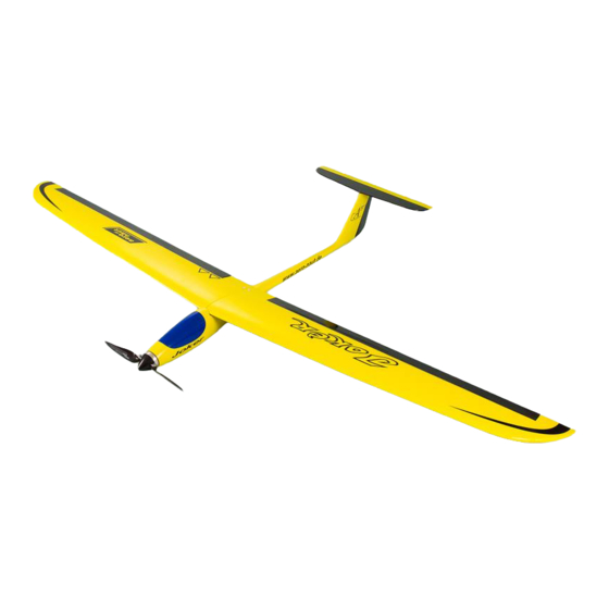
The "Joker" is a fast, agile high-performance model glider which can be built as a glider or with an
electric motor. The two-part wing takes the form of veneered panels with a Styrofoam core. The
moulded GRP fuselage is factory-prepared for the installation of the receiving system components.
The small size of the "Joker" when dismantled makes it an ideal companion for hill walking and hiking.
Specification:
Joker building instructions
Wingspan
Length
All-up weight
Wing area
Wing loading
RC functions:
Joker
approx. 1520 mm
approx. 925 mm
approx. 600 - 950 g
approx. 21.5 dm²
approx. 27.9 - 44.2 g / dm²
Aileron, elevator,
rudder, throttle
1
Advertisement
Table of Contents

Related Manuals for aero-naut Joker RC


Summary of Contents for aero-naut Joker RC
-
Page 1: Building Instructions
Joker Building Instructions Joker RC model aircraft Order No. 1307/00 The “Joker” is a fast, agile high-performance model glider which can be built as a glider or with an electric motor. The two-part wing takes the form of veneered panels with a Styrofoam core. The moulded GRP fuselage is factory-prepared for the installation of the receiving system components. - Page 2 Joker Parts List GRP fuselage GRP, ready made Canopy and latch Ready made Rudder Built-up wood, film-covered Tailplane and elevator Built-up wood, film-covered Wing panel and aileron 2 (l + r) Foam / wood, film-covered Control ‘snake’ / steel pushrod (elevator) Plastic / steel, 800 mm Control ‘snake’...
- Page 3 Joker Wing The wing consists of two panels which are joined using a steel rod before being screwed to the fuselage. No additional retention measures (e.g. adhesive tape) are required. The first step is to install the aileron servos. The maximum thickness is 13 mm, and the servos should be metal-geared types.
- Page 4 Joker The wing is attached to the fuselage by screws which fit in threaded sleeves glued to a plywood support plate. The machined plate can now be glued in place: The first step is to mark the hole positions on the fuse- lage, working through the wings.
- Page 5 Joker Tailplane The tailplane is fixed to the fuselage using two nylon screws. This means that it can be removed for ease of transport, and the screws can shear off in a hard landing. The first step is to open up the marked holes in the tailplane saddle on the fin using a 3.5 mm Ø...
- Page 6 Joker Installing the receiving system in the fuselage The plate for the rudder and elevator servos should be glued in the fuselage towards the rear of the wing saddle area. Ensure that it is positioned low enough to provide clearance between the servos and the underside of the wing, but high enough to prevent the servos fouling the bottom of the fuselage.
- Page 7 Please follow the building instructions to the letter when completing and operating this model. The building instructions include information on safe flying. This model is in no respect a children’s toy. aero-naut Modellbau GmbH & Co KG, Stuttgarter Strasse 18-22, 72766 Reutlingen, www.aero-naut.de Joker building instructions...
Need help?
Do you have a question about the Joker RC and is the answer not in the manual?
Questions and answers