Table of Contents
Advertisement
Advertisement
Table of Contents

Related Manuals for aero-naut TRIPLE SPEED R.E.S. THERMIC


Summary of Contents for aero-naut TRIPLE SPEED R.E.S. THERMIC
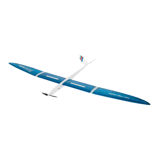
- Page 1 aero naut Triple speed r.e.s. thermic...
- Page 2 Triple geniale 3-fach Modell speed r.e.s. thermic Triple allows you to use different wing designs with the same fuselage. The wings of the Triple series are exchangeable and be employed to match the weather and your requirements. This manuall covers the construction of the fuselage (sailplane and E versions) and three different wings. Please note that not all of the sections in this manual are relevant for your model.
- Page 3 Section I - Fuselage This section is dedicated to the fuselage construction of the E-powered version. Whenever different parts or tequnices are required for building the sailplane fuselage, a special note will guide you to the corresponding section and building step. The fuselage sides are made up of a R-02 front (R-01, light ply) and a rear part...
- Page 4 R-10 For sailplane version see section 4 S. Glue in place formers R-10, R-11 E and R-12 E. Make sure fuselage sides are absolutely symmetrical. R-11 E R-13 For the E-version use a 240 mm long piece of triangular to cut four pieces of R-13 (10 x 10 x 60 mm) to length and glue into corners of fuselage sides.
- Page 5 To the inside of fuselage sides and to the back of rear cockpit former glue magnet supports R-19. Centre R-19 over 8 mm holes for the retaining magnets used for wings and cabin. R-27 R-19 Epoxy in place wing joiner sleeves R-26 and R-27 and sand flush with fuselage sides.
- Page 6 For sailplane version see section 41 S. R-29 Assemble and glue cabin from side panels R-20, formers R-21 and R-22 E as well as 1.5 mm balsa sheeting R-29. For best results this is done directly in the cockpit R-21 opening of the fuselage which is protected by cling film.
- Page 7 For sailplane version see sections 14 S and 15 S. Glue former R-30 E to the front of the fuselage. R-30 needs to be exactly centred on fuselage. Any surplus material will be sanded off later so that different spinner sizes can be fitted to the model. Tip: If you already have the motor you want to use, attach motor to former, wrap a few layers of paper around its drum and slide it into the fulselage for proper position of former R-30 E.
- Page 8 Section II - Sailplane Version Refer to section I for construction of the sailplane version of the fuselage. Section II explains only those building steps and parts that differ from the E version. Assemble horizontal formers R-03.1 to R-03.3 R-04 S with former R-04 S and formers R-05 to R-09 and insert in notches in fuselage side.
- Page 9 11 S Assemble and glue cabin from side panels R-20, formers R-21 and R-22 S as well as 1.5 mm balsa sheeting R-29. For best results this is done directly in the cockpit opening of the fuselage which is protected by cling film. R-21 Note: Magnet support R-23 and magnets are glued in place after cabin has been thoroughly...
-
Page 10: First Of All Assemble The Assebly Jig And Glue Parts L-01 And L
Section III - V-Tail L-02 First of all assemble the assebly jig and glue parts L-01 and L-02 to L-03. Place jig on an even surface and leave to dry. L-01 L-03 Pin down L-04 on the building board and glue trailing edge L-05 at right angles to L-04. - Page 11 Protect the jig with cling film, place L-18 in jig and position V-tail parts. To strengthen the joints, it is a good idea to bevel and in doing so enlarge the contact surfaces. Carefully fit V-tail panels to centre piece L-18, then glue with 5 minute epoxy. L-18 Reinforcement L-20 is used to strengthen the V-tail joint.
- Page 12 Section IV - Triple speed Wing Attention: Make sure you build a left and a right wing panel. In this section construction of one wing panel is described. Build the opposite wing panel accordingly. Protect building board with cling film. Place two parts TS-01 on building board as shown and secure with pins.
- Page 13 Place two-piece trailing edge sheeting TS-05 and TS-07 as well as aileron sheeting TS-06 in the jig as shown. TS-07 TS-06 TS-05 Fit ribs TS-09 to TS-25 in place in numerical order. Root rib TS-08 will be fitted at a later stage.
- Page 14 Cut to length upper spruce spar TS-02 (2 x 8 mm) and glue to ribs and main spar. Use suitable weigths to hold spar in place and leave to dry. TS-02 Glue in place aileron spar TS-28, aileron leading edge TS-29 as well as gussets TS-30 and TS-31. Insert servo tray TS-32 between ribs TS-16 and TS-17 and glue flush with underside of ribs and to wing spar.
-
Page 15: Position
Carefully sand surface of wing joiner sleeve TS-35 and insert in wing root. Insert wing joiner R-40 into sleeve and make sure it moves freely and without binding. Then remove R-40 and glue sleeve in place with epoxy mixed with glass fibres. Align magnet supports TS-46 and TS-47 with corresponding holes in rib TS-08, then glue to the inside of rib T-08. -
Page 16: Position
Remove wing from building board. Please handle with care and always place on an even surface, as the wing has no tortional stability at this time. Glue bottom sheeting material to ribs. For best results use thin CA. Also glue in place sheeting material to the underside of wing root. -
Page 17: Position
Cut off sheeting material flush with false leading edge then carefully sand sheeting material flush with false leading edge. Use a long sanding bar for best results. Then glue leading edge TS-37 (balsa, 3 x 8 mm) to false leading eding edge and sand to shape after glue has dried. -
Page 18: Position
TS-39 Use a razor saw to cut out the aileron and carefully sand sheeting material flush with riblets on either side. Glue TS-39 to front of aileron and bevel off to allow for sufficient control throw. After covering attach aileron to wing with tape. Tip: If you do not want to use tape, you can bevel off top and bottom of TS-39 and use small hinges to attach the aileron to the wing. -
Page 19: Position
Section V - Triple R.E.S. Wing Attention: Make sure you build a left and a right wing panel. In this section construction of one wing panel is described. Build the opposite wing panel accordingly. Protect building board with cling film. Place two parts TR-01 on building board as shown and secure with pins. -
Page 20: Position
Fit ribs TR-07 to TR-15 in place in numerical order. Notches in Spar and trailing edge help to position the ribs correctly. Note, that ribs are glued to spruce spar, main spar and trailing edge sheeting TR-05. Do not apply glue to front part of ribs between wing spar and leading edge position. -
Page 21: Position
Glue bottom sheeting material to ribs. For best results use thin CA. Also glue in place sheeting material to the underside of wing root. Glue together wing root sheeting material TR-16 and TR-17, then glue to first rib bay on underside of wing. -
Page 22: Position
Glue in place top sheeting TR-01 on ribs, spar and flase leading edge. Use suitable weights and tape to secure sheeting material until glue has dried completely. TR-01 Cut off sheeting material flush with false leading edge then carefully sand sheeting material flush with false leading edge. -
Page 23: Position
Section VI - Triple thermic Wing Attention: Make sure you build a left and a right wing panel. In this section construction of one wing panel is described. Build the opposite wing panel accordingly. Protect building board with cling film. Place two parts TT-01 on building board as shown and secure with pins. -
Page 24: Place. Note, That Ribs Are Glued To Spruce Spar, Main Spar, Trailing Edge Sheeting And Aileron
Fit ribs TT-09 to TS-23 in place in numerical order. Glue in place aileron riblets TT-24 and TT-25. Make sure you position ribs exactly at right angles in relation to spar, then glue in place. Note, that ribs are glued to spruce spar, main spar, trailing edge sheeting and aileron sheeting. -
Page 25: Position
Glue in place aileron spar TT-26, aileron leading edge TT-27 as well as gussets TT-28 and TT-29. Insert servo tray TT-30 between ribs TT-14 and TT-15 and glue flush with underside of ribs and to wing spar. TT-29 TT-26 TT-30 TT-15 TT-14 TT-28... -
Page 26: Position
Glue together wing root sheeting material TT-31 and TT-23, then glue to first rib bay. TT-31 TT-32 Remove wing from building board. Please handle with care and always place on an even surface, as the wing has no tortional stability at this time. -
Page 27: Position
Place wing on building board and glue false leading edge TT-33 (balsa, 2 x 8 mm) to ribs and bottom sheeting. Sand flush with top of ribs after glue has dried. TT-33 Glue in place top sheeting TT-01 on ribs, spar and false leading edge. -
Page 28: Position
Make up wing tips from 3 parts TT-35 and secure with clamps until dry. Sand sheeting material and spars flush with tip rib TT-23 and glue in place wing tip TT-35. Then sand wing tip to fit planform of wing and shape of wing section. TT-35 Use a razor saw to cut out the aileron and carefully sand... -
Page 29: Position
Section VII - R.E.S. and thermic Centre Section Attention: Make sure you build a left and a right wing panel. In this section construction of one wing panel is described. Build the opposite wing panel accordingly. Protect building board with cling film. Place two parts TM-01 on building board as shown and secure with pins. -
Page 30: Sheeting. Do Not Apply Glue To Front Part Of Ribs Between Wing Spar And Leading Edge
Fit ribs TM-08 to TM-17 in place. Make sure you position ribs exactly at right angles in relation to spar, then glue in place. Note, that ribs are glued to spruce spar, main spar and trailing edge sheeting. Do not apply glue to front part of ribs between wing spar and leading edge position. -
Page 31: Position
Insert servo tray TM-20 between ribs in 4 rib bay and glue flush with underside of ribs and to wing spar. Insert wing joiner R-40 into sleeve TM-21 and make sure it moves freely and without binding. Carefully sand surface of wing joiner sleeve TM-21 and insert in wing root. -
Page 32: Position
Glue together wing root sheeting material TM-22 and TM-23, then glue to first rib bay on either side of wing. TM-22 TM-23 Place wing on building board and glue false leading edge TM-24 (balsa, 2 x 8 mm) to ribs and bottom sheeting. -
Page 33: Position
Sand sheeting material flush with false leading edge. Use a long sanding bar for best results. Glue leading edge TM-25 (balsa, 3 x 8 mm) to false leading eding edge and sand to shape after glue has dried. TM-25 Glue control horn TM-27 to spoiler TM-26. Make sure to build a left and a right spoiler! File a notch for control horn TM-27 and fit spoiler in place. - Page 34 Section VIII - Abschlussarbeiten Attach control surfaces to V-tail with tape and temporarily mount V-tail on fuselage. Make a Z-bend at one end of 0.8 mm piano wires R-37, slide control horns over Z-bends and insert wires into snakes R-28. Mark positions of control horns on control surfaces and und fit control horn in place.
- Page 35 F0r speed and thermic only: Use servos with a max. thickness of 11.5 mm for aileron control. Install pushrod connectors R-38 on outer most position of servo arms and adjust neutral position of servos. Position servo on servo tray and mark position of servo arm. Cut piano wire TS-43 (speed) or TT-38 (thermic) to length and make a Z-bend at one end.
- Page 36 Item Pieces Material Laser sheet Type Dimensions R-35 S lower noseblock (sailplane) balsa laser cut 3 mm R-36 wing retainer magnet ready made Ø 8 x 3 mm Ø 0.8 x 1,000 mm R-37 pushrod piano wire cut part ready made Ø 4.5 / 2 x 10 mm R-38 pusrod connector (with nut/grub screw) metal Ø...
- Page 37 Item Pieces Material Laser sheet Type Dimensions R-08 former light ply laser cut 3 mm R-09 former light ply laser cut 3 mm R-10 former light ply laser cut 3 mm R-11 E former (electric glider) light ply laser cut 3 mm R-11 S former (sailplane) light ply...
- Page 38 Item Pieces Material Laser sheet Type Dimensions TM-27 control horn plywood laser cut 3 mm TM-28 wing joiner plywood laser cut 1 mm TM-29 wing locating dowel beech cut part Ø 3 x 20 mm TM-30 wing retainer magnet ready made Ø...
- Page 39 Item Pieces Material Laser sheet Type Dimensions 3 mm L-03 V-tail jig light ply laser cut 3 mm L-04 V-tail base balsa laser cut 3 mm L-05 V-tail trailing edge balsa laser cut 3 mm L-06 V-tail leading edge balsa laser cut L-07 V-tail brace balsa...
- Page 40 2.000 mm ARF-kit with GRP fuselage and ready covered rib wings SHK 1125/01 wingspan 4.000 mm Lasercut kit with GRP fuselage and depron jig aero naut aero-naut Modellbau can be found on www.aero-naut.com Stuttgarter Strasse 18-22 D-72766 Reutlingen Germany www.aero-naut.com...
Need help?
Do you have a question about the TRIPLE SPEED R.E.S. THERMIC and is the answer not in the manual?
Questions and answers