Table of Contents
Advertisement
Quick Links
MOUNTING AND
OPERATING INSTRUCTIONS
EB 01b
Translation of the original manual
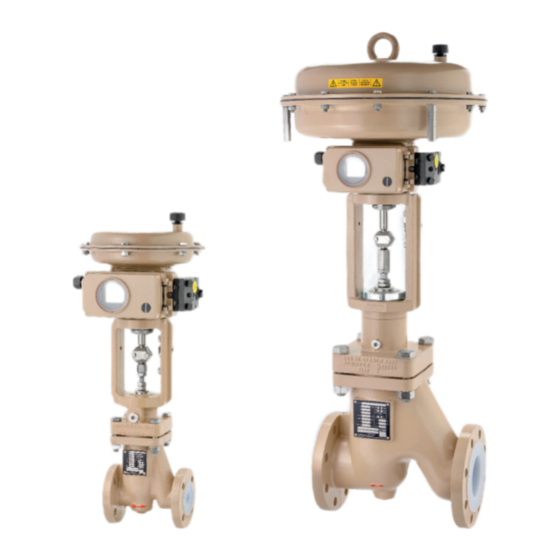
Control valve BR 01b • DIN and ANSI version
to combine with actuators
February 2022 edition
PFEIFFER Chemie-Armaturenbau GmbH · Hooghe Weg 41 · 47906 Kempen · Germany
Phone: +49 2152 2005-0 · Fax: +49 2152 1580
sales-pfeiffer-de@samsongroup.com · www.pfeiffer-armaturen.com
Advertisement
Table of Contents

Related Manuals for Samson EB 01b


Summary of Contents for Samson EB 01b
- Page 1 MOUNTING AND OPERATING INSTRUCTIONS EB 01b Translation of the original manual Control valve BR 01b • DIN and ANSI version to combine with actuators February 2022 edition PFEIFFER Chemie-Armaturenbau GmbH · Hooghe Weg 41 · 47906 Kempen · Germany Phone: +49 2152 2005-0 · Fax: +49 2152 1580...
- Page 2 Note regarding this installation and operating manual This Installation and Operating Manual (EB) provides guidance for safe assembly and operation. The notes and instructions in this EB are binding when handling PFEIFFER devices. The fi gures and illustrations in this EB are examples and must therefore be considered as such.
-
Page 3: Table Of Contents
4.3.2 Lifting Storing the valve Installation Installation conditions Preparing for assembly Assembling the valve and actuator 5.3.1 Travel adjustment with separately supplied SAMSON actuator 5.3.2 Travel limit Installing the valve in the pipe 5.4.1 General 5.4.2 Installing the valve Checking the assembled valve 5.5.1... - Page 4 Contents Start-up Operation Malfunction Detecting and rectifying errors Carrying out emergency measures Servicing Periodic tests Maintenance work 9.2.1 Replacing the seat and plug 9.2.2 Replacing the bellows 9.2.3 Replacing the V-ring packing Ordering spare parts and consumables 10 Decommissioning 10-1 11 Removal 11-1 11.1...
-
Page 5: Safety Instructions And Safety Measures
ature range for these valves TB 01b. and is indicated on the type plate of SAMSON actuators, see − The safety regulations that apply to the pipe system in which the actuator documentation. the valves are installed and to the control system to which the −... -
Page 6: Notes Regarding Possible Severe Personnel Injury
Safety instructions and safety measures − A actuator unit that is subsequently installed on the valve is 1.1 Notes regarding possible severe adapted to the valve and is correctly adjusted in the end po- personnel injury sitions, and in particular in the closed position of the valve. −... -
Page 7: Notes Regarding Possible Property Damage
Valves that are equipped with preloaded actuator springs are un- der mechanical tension. These valves, in combination with the NOTE pneumatic SAMSON actuators, can be identifi ed by the elon- gated screws on the bottom of the actuator. Damage to the valve due to contamination! Before working on the actuator, release the compression from Contamination (e.g. -
Page 8: Warning Notes On The Device
Safety instructions and safety measures NOTE Damage to the valve due to unsuitable lubricants! Unsuitable lubricants can corrode and damage the surface. The valve material requires suitable lubricants, see Chapter “15.1.2 Lubricants”. 1.4 Warning notes on the device Warning of moving parts Figure 1-1: Warning of moving parts There is a danger of crushing due to the lifting movements of the actuator and plug stem when reaching into the yoke as long as... -
Page 9: Markings On The Device
Markings on the device Markings on the device Each valve using has the following marking. Table 2-1: Marking on the type plate and on the body of the valve Pos. Marking Remark Manufacturer PFEIFFER Address see Chapter “15.3 Service” Valve type BR (and number value) e.g. -
Page 10: Type Plates
Markings on the device 2.1 Type plates 2.1.1 Valve type plate Figure 2-1: Marking positions of the type plate on the valve BR 01b 2.1.2 Actuator type plate See the corresponding actuator documentation. 2.2 Material marking The valves are marked on the body with material specifi cation, see Table 2-1. -
Page 11: Design And Principle Of Operation
Design and principle of operation The BR 01b valve can be selected in the following versions: Function and principle of operation − With a pneumatic SAMSON actuator. The medium fl ows through the valve in the closing direction. − With a manual SAMSON actuator. - Page 12 Design and principle of operation Figure 3-1: Sectional diagram of a valve manufactured after 2006 Table 3-1: Parts list Pos. Designation Pos. Designation Valve body Distance bush Bonnet fl ange V-ring packing Seat Set of spring washers Plug Bearing bush Bellows O-ring Cord...
-
Page 13: Attachments
Design and principle of operation 3.3 Attachments Info The following accessories are available either individually or in The positions and arrangements of the individual parts shown in combinations: the drawings must be observed during assembly. − Positioner − Limit switch −... - Page 14 Damage to the bonnet fl ange due to improper handling! Chapter “5.3.1 Travel adjustment with separately supplied Do not damage the bonnet fl ange, especially the thread on SAMSON actuator”. the stem end. Press the lower bearing bushing (11) into the upper part of 3.5.1.6 Final assembly of the valve (version...
-
Page 15: Assembly Of The Valve From Dn 80 / Nps3, Manufactured Before 2006
Design and principle of operation Grease the stem (12) on the bottom thread. Info Screw the bellows (5) with a preassembled washer and bush- Do not tighten the stuffi ng box, the distance between the collar of ing onto the greased thread of the stem (12). the stuffi... - Page 16 Design and principle of operation Figure 3-3: Sectional diagram of valve BR 01b manufactured before 2006 Table 3-2: Parts list Pos. Designation Pos. Designation Valve body Bearing bush Bonnet fl ange O-ring Seat Stuffi ng box Plug Screw Bellows Cord Retainer ring O-ring Thrust washer...
- Page 17 Screw the lock nuts (24) onto the stem. Adjust the nuts, see (19). Chapter “5.3.1 Travel adjustment with separately supplied SAMSON actuator”. Press the upper bearing bushing (17) into the bottom part of the stuffi ng box (19). Grease the stuffi ng box (19) on the thread.
- Page 18 Design and principle of operation EB 01b_EN February 2022 edition Subject to technical changes...
-
Page 19: Shipment And On-Site Transport
Damage to the valve due to improper fastening of the sling! Check the scope of supply. Compare the delivered goods The welded-on lifting eyes on SAMSON actuators are used only with the delivery note. for actuator assembling and disassembling as well as for lifting Check the supply for transport damage. -
Page 20: Storing The Valve
Shipment and on-site transport DANGER Danger due to incorrect lifting and transport! The lifting points for the lifting slings shown in the schematic drawing serve as examples for most valve variants. On site the conditions for lifting and transporting the valve can change how- ever. - Page 21 Shipment and on-site transport The valve must be stored in its protective packaging and/or with the protective caps on the connection ends. The packaging should protect the scratch-sensitive plastic lin- ing of the valve against damage. Valves that weigh more than approx. 10 kg should be stored on a pallet (or supported similarly).
- Page 22 Shipment and on-site transport EB 01b_EN February 2022 edition Subject to technical changes...
-
Page 23: Installation
Installation When connecting the attachments, make sure that they can Installation be accessed from the operator level safely and easily. The work described in this chapter may only be performed by specialist personnel qualifi ed to perform the corresponding task. The following instructions apply additionally for valves. -
Page 24: Travel Adjustment With Separately Supplied Samson Actuator
½ 1½ Damage to the valve due to incorrect travel adjustment! 175v2 cm • • • If a SAMSON actuator is retrofi tted, a preadjustment of the travel 240 cm • • • is necessary: 350 cm • •... -
Page 25: Installing The Valve In The Pipe
(19). The use of PTFE fl ange seals is recommended. Theoretical travel (SAMSON actuator) 15 +0.5 to 1 mm The counterfl anges must have smooth sealing surfaces. Other shapes must be agreed upon with PFEIFFER. -
Page 26: Installing The Valve
Installation The connection ends of the pipes must align with the valve 5.4.2 Installing the valve connections and have plane-parallel ends. Connection fl ang- Close the valve in the pipe for the duration of the installation. es that are not plane parallel can damage the PFA lining dur- ing installation! Remove the protective caps on the valve openings prior to in- stallation. -
Page 27: Pressure Test Of The Pipe Section
Installation WARNING Danger due to improperly executed control commands! Incorrectly executed control commands can cause serious injuries or even death and cause damage to the pipe system. Check the actuator unit and control command., see chap- ter “8 Faults” 5.5.2 Pressure test of the pipe section The pressure test was already performed on the valves by PFEIFFER. - Page 28 Installation EB 01b_EN February 2022 edition Subject to technical changes...
-
Page 29: Start-Up
Start-up Open the valve slowly in the pipe. Opening slowly prevents a Start-up sudden increase in pressure and a resulting high fl ow speed The work described in this chapter may only be performed by that damages the valve. specialist personnel qualifi ed to perform the corresponding task. Check the correct function of the valve. - Page 30 Start-up EB 01b_EN February 2022 edition Subject to technical changes...
-
Page 31: Operation
Operation − Upon customer request, these valves can also be equipped Operation without a test connection. As soon as the commissioning/recommissioning work is If a valve leaks, observe chapter “8 Faults”. complete, see Chapter “6 Commissioning”, the valve is ready for operation. - Page 32 Operation EB 01b_EN February 2022 edition Subject to technical changes...
-
Page 33: Malfunction
Malfunction Malfunction When rectifying the faults, chapter “1 Safety instructions and safety measures” must be observed. 8.1 Detecting and rectifying errors Type of fault Possible cause Measure Leaks in the pipe connection The fl ange connection of the Tighten the fl ange screws. lined valve is leaky NOTE An excessive tightening torque when retightening the fl... - Page 34 Malfunction Type of fault Possible cause Measure Leaks in the stem sealing Medium escapes from the If the valve on the stuffi ng box is leaky, the bellows is defective. stuffi ng box DANGER Danger of injury due to hazardous media! It must be kept in mind that the media is usually hazardous.
-
Page 35: Carrying Out Emergency Measures
Malfunction 8.2 Carrying out emergency measures In the case of a power supply failure, the valve automatically switches to the preset fail-safe position, (see “Fail-safe positions” in Chapter “3 Design and principle of operation”. The system operator is responsible for emergency measures. In case of a valve fault: −... - Page 36 Malfunction EB 01b_EN February 2022 edition Subject to technical changes...
-
Page 37: Servicing
Servicing Servicing NOTE The work described in this chapter may only be performed by Damage to the valve due to excessively high or low tightening specialist personnel qualifi ed to perform the corresponding task. torques! The following documents are required in addition for the mainte- The valve components must be tightened with specifi... -
Page 38: Maintenance Work
Servicing 9.2.3 Replacing the V-ring packing Measures in the case of a negative Test test result Check the condition of the V-ring packing. Check the lifting movement of Tighten the packing correctly. the actuator stem and stem for If the actuator stem and stem are Remove the V-ring packing (15) as described in Chapter linear, smooth movement. -
Page 39: Decommissioning
Decommissioning 10 Decommissioning The work described in this chapter may only be performed by specialist personnel qualifi ed to perform the corresponding task. WARNING Danger of burning due to hot or cold components and pipe! Valve components and pipes can become very hot or very cold during operation and cause burns upon contact. - Page 40 Decommissioning EB 01b_EN 10-2 February 2022 edition Subject to technical changes...
-
Page 41: Removal
Do not loosen the test connection while the valve is pressur- ised. Danger of injury due to prestressed springs! SAMSON actuators with preloaded actuator springs are pressurised. These actuators can be identifi ed by the elongat- ed screws on the bottom of the actuator. - Page 42 Removal EB 01b_EN 11-2 February 2022 edition Subject to technical changes...
-
Page 43: Repairs
Repairs Release the stuffi ng box (19) and screw it out of the bonnet 12 Repairs fl ange. If the valve no longer works properly or if it does not work at all, Remove the PFFE V-ring packing (15), check for damage and it is defective and must be repaired or replaced. - Page 44 Repairs Figure 12-2: Section diagram of valve BR 01b EB 01b_EN 12-2 February 2022 edition Subject to technical changes...
-
Page 45: Replacing The Plug And Seat
Repairs Table 12-1: Parts list Pos. Designation Pos. Designation Pos. Designation Valve body Bearing bush Bonnet fl ange Stem Retainer ring Seat Locking screw O-ring Plug Distance bush Bellows V-ring packing Yoke Cord Set of spring washers Slotted nut O-ring Bearing bush Bush Thrust washer... - Page 46 Repairs Include the following information for returns: − Manufacturer number − Valve type − Article number − Nominal size and version of the valve − Manual valve/automated valve − Medium (designation and consistency) − Medium pressure and temperature − Flow rate in m³/h −...
-
Page 47: Disposal
Disposal 13 Disposal For disposal, observe the local, national and international regulations. Do not dispose of old components, lubricant and hazardous materials with domestic waste. EB 01b_EN 13-1 February 2022 edition Subject to technical changes... - Page 48 Disposal EB 01b_EN 13-2 February 2022 edition Subject to technical changes...
-
Page 49: Certifi Cates
Certifi cates 14 Certifi cates The declaration of conformity is available on the following pages: − Declaration of conformity according to Pressure Equipment Directive 2014/68/EU for automated valves, see page 14-2. − Declaration of conformity according to Pressure Equipment Directive 2014/68/EU for manually operated valves, see page 14-3. - Page 50 Certifi cates EB 01b_EN 14-2 February 2022 edition Subject to technical changes...
- Page 51 Certifi cates EB 01b_EN 14-3 February 2022 edition Subject to technical changes...
- Page 52 Certifi cates EB 01b_EN 14-4 February 2022 edition Subject to technical changes...
- Page 53 Certifi cates EB 01b_EN 14-5 February 2022 edition Subject to technical changes...
- Page 54 Certifi cates EB 01b_EN 14-6 February 2022 edition Subject to technical changes...
-
Page 55: Annex
Annex Table 15-4: Tightening values for the ANSI fl ange connections 15 Annex NPS [inch] ½ 1½ 15.1 Tightening torques, lubricant and tools MA [Nm] On request 15.1.1 Tightening torques 15.1.1.1 Bonnet fl ange 15.1.2 Lubricant For the connection of the bonnet fl ange (2) with the valve body, Table 15-5: Recommended lubricant the screw connections are tightened in a criss-cross pattern with the tightening torques indicated below. -
Page 56: Spare Parts For Valves Manufactured After 2006
Annex 15.2.1 Spare parts for valves manufactured after 2006 Figure 15-1: Exploded drawing of the valve manufactured after 2006 EB 01b_EN 15-2 February 2022 edition Subject to technical changes... - Page 57 Annex Table 15-6: Recommended spare parts for valves manufactured after 2006 In the spare parts set Included in the set of In the spare parts for Pos. Designation Material for commissioning seals 2 year operation Valve body EN-JS 1049 / PFA Bonnet fl...
-
Page 58: Spare Parts For Valves Manufactured Before 2006
Annex 15.2.2 Spare parts for valves manufactured before 2006 Figure 15-2: Exploded drawing of the valve manufactured before 2006 EB 01b_EN 15-4 February 2022 edition Subject to technical changes... - Page 59 Annex Table 15-7: Recommended spare parts for valves manufactured before 2006 In the spare parts set Included in the set of In the spare parts for Pos. Designation Material for commissioning seals 2 year operation Valve body EN-JS 1049 / PFA Bonnet fl...
-
Page 60: Service
Annex 15.3 Service For maintenance and repair work as well as malfunctions or de- fects, contact the After Sales Service at PFEIFFER for support. E-mail The After Sales Service can be reached at the e-mail address “sales-pfeiffer-de@samsongroup.com”. Necessary data Provide the following information in the case of questions and for troubleshooting: −... - Page 61 EB 01b_EN February 2022 edition Subject to technical changes...
- Page 62 EB 01b_EN February 2022 edition Subject to technical changes...
- Page 63 EB 01b_EN February 2022 edition Subject to technical changes...
- Page 64 PFEIFFER Chemie-Armaturenbau GmbH Hooghe Weg 41 · 47906 Kempen Phone: +49 2152 2005-0 · Fax: +49 2152 1580 E-Mail: sales-pfeiffer-de@samsongroup.com · Internet: www.pfeiffer-armaturen.com EB 01b_EN February 2022 edition Subject to technical changes...
Need help?
Do you have a question about the EB 01b and is the answer not in the manual?
Questions and answers