
Subscribe to Our Youtube Channel
Related Manuals for Samson EB 8111 EN


Summary of Contents for Samson EB 8111 EN
- Page 1 EB 8111/8112 EN Translation of original instructions Type 3321 Valve DIN and ANSI versions Edition March 2020...
- Page 2 Note on these mounting and operating instructions These mounting and operating instructions assist you in mounting and operating the device safely. The instructions are binding for handling SAMSON devices. The images shown in these instructions are for illustration purposes only. The actual product may vary.
-
Page 3: Table Of Contents
Contents Safety instructions and measures ..............1-1 Notes on possible severe personal injury ............1-4 Notes on possible personal injury ..............1-4 Notes on possible property damage .............1-6 Markings on the device ................2-1 Valve nameplate ..................2-1 Actuator nameplate ..................2-2 Material numbers ..................2-2 Design and principle of operation ...............3-1 Fail-safe action ...................3-3 Versions .....................3-3 3.3... - Page 4 Removal ....................11-1 11.1 Removing the valve from the pipeline ............11-1 11.2 Removing the actuator from the valve ............11-2 Repairs ....................12-1 12.1 Returning devices to SAMSON ..............12-1 Disposal ....................13-1 Certificates ....................14-1 Annex......................15-1 15.1 Tightening torques, lubricants and tools ............15-1 15.2 Spare parts ....................15-1 15.3...
-
Page 5: Safety Instructions And Measures
SAMSON does not assume any liability for damage resulting from the failure to use the de- vice for its intended purpose or for damage caused by external forces or any other external factors. - Page 6 (see associated actuator documentation). When the valve is combined with one of the following SAMSON actuators, the valve moves to a certain fail-safe position (see the 'Design and principle of operation' section) upon supply air or control signal failure.
- Page 7 Safety instructions and measures Responsibilities of the operator The operator is responsible for proper operation and compliance with the safety regulations. Operators are obliged to provide these mounting and operating instructions as well as the referenced documents to the operating personnel and to instruct them in proper operation. Furthermore, the operator must ensure that operating personnel or third persons are not ex- posed to any danger.
-
Page 8: Notes On Possible Severe Personal Injury
Safety instructions and measures 1.1 Notes on possible severe personal injury DANGER Risk of bursting in pressure equipment. Valves and pipelines are pressure equipment. Impermissible pressure or improper opening can lead to valve components bursting. Î Observe the maximum permissible pressure for valve and plant. Î... - Page 9 Î Wear eye protection when working in close proximity to the control valve. Risk of personal injury due to preloaded springs. Valves in combination with pneumatic actuators with preloaded springs are under ten- sion. These control valves with SAMSON pneumatic actuators can be identified by the long bolts protruding from the bottom of the actuator. Î Before starting any work on the actuator, relieve the compression from the preload- ed springs (see associated actuator documentation).
-
Page 10: Notes On Possible Property Damage
Safety instructions and measures WARNING Risk of personal injury due to residual process medium in the valve. While working on the valve, residual process medium can escape and, depending on its properties, may lead to personal injury, e.g. (chemical) burns. Î... - Page 11 Risk of valve damage due to the use of unsuitable tools. Certain tools are required to work on the valve. Î Only use tools approved by SAMSON (u AB 0100). Risk of valve damage due to the use of unsuitable lubricants. The lubricants to be used depend on the valve material. Unsuitable lubricants may cor- rode and damage the surface.
- Page 12 EB 8111/8112 EN...
-
Page 13: Markings On The Device
Markings on the device 2 Markings on the device Note Fig. 2-1 and the inscription table list all 2.1 Valve nameplate possible characteristics and options that may appear on a valve nameplate. Only the inscriptions relevant to the ordered Type 3321 Valve actually appear on the nameplate. -
Page 14: Actuator Nameplate
Markings on the device The valve nameplate (80) in valve sizes DN 15 to 50 or NPS ½ to 2 is affixed to the valve on the body flange (Fig. 2-2). The nameplate is affixed to the top of the bonnet in valve sizes DN 65 or NPS 2½ and larger (Fig. 2-3). Fig. 2-2: Nameplate Fig. 2-3: Nameplate on the body on the bonnet 2.2 Actuator nameplate See associated actuator documentation. 2.3 Material numbers The seat and plug of the valves have an item number written on them. -
Page 15: Design And Principle Of Operation
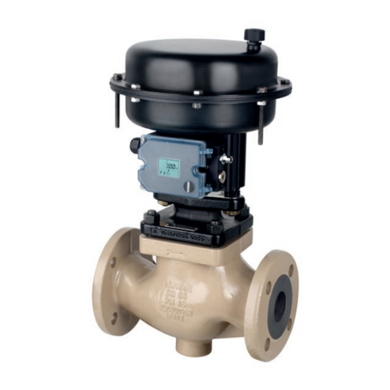
The Type 3321 Valve is a single-seated stem connector (A30/A31) and sealed by globe valve. This valve is preferably to be the spring-loaded packing (15). combined with the following SAMSON actu- The process medium flows through the valve ators: in the direction indicated by the arrow in the − Type 3371 Pneumatic Actuator flow-to-open direction. The plug position de- termines the cross-sectional area between −... - Page 16 Design and principle of operation Fig. 3-2: Type 3321 Valve, DN 65 to 100/NPS 2½ to 4; mounting using rods (form C) Legend for Fig. 3-1 and Fig. 3-2 1 Body 14 Body nut A3/A7 Actuator stem 2 Valve bonnet 15 Packing A11/A33 Rod 4 Seat 17 Body gasket A17 Crossbeam 5 Plug (with plug stem) 96 Flange bonnet A25 Nut 8 Threaded bushing...
-
Page 17: Fail-Safe Action
Actuators of SAMSON actuators is specified on the ac- tuator nameplate. In these instructions, the preferable combina- Upon supply voltage failure, the Type 3374 tion with one of the following SAMSON ac- Electric Actuator (version with fail-safe action tuators is described. only) causes the valve to move to a certain − Type 5824 Electric Actuator fail-safe position. -
Page 18: Valve Accessories
ANSI/FCI 70-2) Information Sheet u T 8350 Noise emissions 3.5 Technical data SAMSON is unable to make general state- The nameplates on the valve and actuator ments about noise emissions. The noise emis- provide information on the control valve ver- sions depend on the valve version, plant fa- sion. - Page 19 Design and principle of operation Table 3-1: Dimensions and weights for Type 3321 Valve · DIN version Valve Dimension A H4 (with insulating section) Weight Weight (with insulating section) Table 3-2: Dimensions and weights for Type 3321 Valve · ANSI version ½ ¾ 1½ 2½...
- Page 20 Note Refer to the following data sheets for more dimensions and weights: u T 8111 and u T 8112 The associated actuator documentation applies to actuators, e.g. for SAMSON actuators: u T 8313 for Type 3372 Electropneumatic Actuator u T 8317 for Type 3371 Pneumatic Actuator u T 5824 for Type 5824 Electric Actuator u T 8331 for Type 3374 Electric Actuator...
-
Page 21: Shipment And On-Site Transport
2. Check the shipment for transportation Î Stay clear of suspended or moving damage. Report any damage to loads. SAMSON and the forwarding agent Î Close off and secure the transport paths. (refer to delivery note). 3. Determine the weight and dimensions of WARNING... - Page 22 Shipment and on-site transport WARNING NOTICE Risk of personal injury due to the control Risk of valve damage due to incorrectly at- valve tipping over. tached slings. Î Observe the valve's center of gravity. Î When lifting the control valve, make sure Î...
-
Page 23: Transporting The Valve
Shipment and on-site transport 4.3.1 Transporting the valve ping off the hook during lifting and transporting. The control valve can be transported using − Secure slings against slipping. lifting equipment (e.g. crane or forklift). − Make sure the slings can be removed Î... -
Page 24: Storing The Valve
Î Observe the storage instructions. vent cracking, do not bend them or hang Î Avoid long storage times. them up. Î Contact SAMSON in case of different − We recommend a storage temperature of storage conditions or long storage peri- 15 °C (59 °F) for elastomers. -
Page 25: Installation
The work position for the control valve is the process conditions and are intended as rec- front view looking onto the operating con- ommendations. Contact SAMSON if the trols (including valve accessories). Table 5-1: Inlet and outlet lengths Flow rate... -
Page 26: Preparation For Installation
Î Observe the recommended inlet and Î During connection of valve accessories, outlet lengths (see Table 5-1). Contact make sure that they are easily accessible SAMSON if the valve conditions or states and can be operated safely from the of the medium process deviate. work position. -
Page 27: Mounting And Installing The Device
Risk of valve damage due to the use of un- work. suitable tools. Î Flush the pipelines. Î Only use tools approved by SAMSON (u AB 0100). Note The plant operator is responsible for clean- 5.3.1 Mounting the actuator ing the pipelines in the plant. - Page 28 Installation a) Pneumatic or electropneu- b) Electric actuator matic actuator When an electric actuator is mounted onto the valve, it is mounted with a form-fit con- There are two different types of attachment nection using a stem connector and yoke. to mount the pneumatic or electropneumatic actuator onto the valve depending on the version (valve size etc.): mounting using crossbeam or mounting using rods (see Table 5-2).
- Page 29 Installation Fig. 5-1: Mounting using crossbeam and central nut (form B attachment) Type 3321-PP Type 3321-IP Type 3321-E1 Type 3321-E3 Fig. 5-2: Mounting using rods (form C attachment) Type 3321-PP Type 3321-IP Legend for Fig. 5-1 and Fig. 5-2 Central nut Crossbeam Plate EB 8111/8112 EN...
-
Page 30: Installing The Valve Into The Pipeline
Installation 5.3.2 Installing the valve into Î Drain the process medium from all the plant sections concerned as well as the the pipeline valve. 1. Close the shut-off valves in the pipeline at the inlet and outlet of the plant section DANGER while the valve is being installed. Risk of electric shock. - Page 31 Installation Î Before working on the control valve, dis- Î Before starting any work on the actuator, connect and lock the pneumatic air sup- relieve the compression from the pre- ply as well as the control signal. loaded springs (see associated actuator Î...
-
Page 32: Leak Test
Installation To test the valve functioning before start-up Î Apply the maximum and minimum con- or putting back the valve into operation, per- trol signals to check the end positions of form the following tests: the valve while observing the movement of the actuator stem. -
Page 33: Start-Up
Start-up 6 Start-up Î Before working on the control valve, disconnect and lock the pneumatic air The work described in this section is only to supply as well as the control signal. be performed by personnel qualified for the Î Disconnect the supply voltage before assignment accordingly. performing any work on the control valve. - Page 34 Start-up − The prevailing conditions in the plant section concerned meet the valve sizing requirements (see information under 'Intended use' in the 'Safety instructions and measures' section). Start-up/putting the valve back into opera- tion 1. Allow the valve to cool down or warm up to reach ambient temperature before start-up when the ambient temperature and process medium temperature differ greatly or the medium properties require...
-
Page 35: Operation
Operation 7 Operation WARNING WARNING Immediately after completing start-up or put- Crush hazard arising from actuator and ting the valve back into operation (see the plug stem moving. 'Start-up' section), the valve is ready for use. Î Do not insert hands or finger into the yoke while the valve is in operation. - Page 36 EB 8111/8112 EN...
-
Page 37: Malfunctions
Malfunctions 8 Malfunctions Read hazard statements, warnings and caution notes in the 'Safety instructions and mea- sures' section. 8.1 Troubleshooting Malfunction Possible reasons Recommended action Actuator and plug stem Actuator is blocked. Check attachment. does not move on de- Unblock the actuator. mand. -
Page 38: Emergency Action
Malfunctions Malfunction Possible reasons Recommended action Increased flow through Dirt or other foreign Shut off the section of the pipeline and flush the closed valve (seat leak- particles deposited valve. age) between the seat and plug. Valve trim is worn out. Replace seat and plug (see the 'Servicing' section) or contact our after-sales service. The valve leaks to the Defective packing Replace packing (see the 'Servicing' section) or... -
Page 39: Servicing
Servicing 9 Servicing DANGER The work described in this section is only to Risk of electric shock. be performed by personnel qualified for the Î Do not remove any covers to perform assignment accordingly. adjustment work on live parts. Î Before performing any work on the The following documents are also necessary device and before opening the device, for servicing the valve:... - Page 40 Servicing WARNING WARNING WARNING Crush hazard arising from actuator and Risk of personal injury due to preloaded plug stem moving. springs. Î Do not insert hands or finger into the Actuators with preloaded springs are under yoke while the valve is in operation. tension.
-
Page 41: Periodic Testing
Risk of valve damage due to the use of instructions is performed without prior unsuitable tools. agreement by SAMSON's after-sales ser- Î Only use tools approved by SAMSON vice. (u AB 0100). − Only use original spare parts by SAMSON, which comply with the original specifications. -
Page 42: Preparing The Valve For Service Work
Servicing Inspection and testing Action to be taken in the event of a negative result: Check the valve's seat leakage. Shut off the section of the pipeline and flush the valve to remove any dirt and/or deposited foreign particles between the seat and plug. Check the valve for external damage Remove any damage immediately. If necessary, put the (e.g. corrosion). control valve out of operation (see the 'Decommissioning' section). Check the valve accessories to ensure Tighten the connections of the valve accessories. they are mounted properly. -
Page 43: Mounting The Valve After Service Work
Servicing 2. Adjust lower or upper signal bench Note range. See associated actuator docu- To remove a pneumatic actuator with "stem mentation. extends" fail-safe action and/or with pre- 3. If the valve has been removed, re-install loaded springs, a certain signal pressure the valve into the pipeline (see the 'Instal- must be applied to the actuator (see associ- lation' section). - Page 44 Servicing 1 Body 2 Valve bonnet 4 Seat 5 Plug (with plug stem) 8 Threaded bushing (packing nut) 13 Bolt 14 Body nut 15 Packing Fig. 9-1: Form B attachment (mounting using a central nut) 17 Body gasket 96 Flange bonnet 97 Flange 98 Central nut A11 Rod A17 Crossbeam...
-
Page 45: Replacing The Gasket
Servicing 9.4.1 Replacing the gasket 5. Place the valve bonnet (2) and plug with plug stem (5) onto the body. 6. Press the plug (5) firmly into the seat (4), a) For mounting using cross- while fastening down the valve bonnet beam and central nut (2) with the body nuts (14). Tighten the (form B) nuts gradually in a crisscross pattern. - Page 46 Servicing 8. Slide the plug with plug stem (5) into the 9. Carefully place the valve bonnet (2) over valve body (1). the plug stem onto the body. 9. Place the flange bonnet (96) and the 10. Carefully slide the packing parts over the flange (97) over the plug stem and studs plug stem into the packing chamber us- (13) onto the body. ing a suitable tool. Observe the proper sequence (see Fig. 9-3).
-
Page 47: Replacing The Seat And Plug
Servicing When replacing the seat and plug, we also recommend replacing the gasket and pack- ing. See sections 9.4.1 and 9.4.2. a) For mounting using cross- beam and central nut (form B) 1. Undo the body nuts (14) gradually in a crisscross pattern. 2. -
Page 48: Ordering Spare Parts And Operating Supplies
3. Replace the gasket as described in sec- Contact your nearest SAMSON subsidiary tion 9.4.1. or SAMSON's After-sales Service for infor- 4. Unscrew the threaded bushing (8). mation on spare parts, lubricants and tools. 5. Pull the plug with plug stem (5) out of the Spare parts valve bonnet (2). - Page 49 Servicing EB 8111/8112 EN 9-11...
- Page 50 9-12 EB 8111/8112 EN...
-
Page 51: Decommissioning
Decommissioning 10 Decommissioning WARNING The work described in this section is only to Risk of burn injuries due to hot or cold com- be performed by personnel qualified for the ponents and pipeline. assignment accordingly. Valve components and the pipeline may be- come very hot or cold. Risk of burn injuries. Î... - Page 52 Decommissioning Î Do not impede the movement of the actu- 1. Close the shut-off valves upstream and ator and plug stem by inserting objects downstream of the control valve to stop into the yoke. the process medium from flowing through the valve. Î Before unblocking the actuator and plug stem after they have become blocked 2.
-
Page 53: Removal
Removal 11 Removal WARNING WARNING The work described in this section is only to Risk of personal injury due to residual pro- be performed by personnel qualified for the cess medium in the valve. assignment accordingly. While working on the valve, residual process medium can escape and, depending on its properties, may lead to personal injury, e.g. -
Page 54: Removing The Actuator From The Valve
Removal 3. Remove the valve from the pipeline (see the 'Shipment and on-site transport' sec- tion). 11.2 Removing the actuator from the valve See associated actuator documentation. 11-2 EB 8111/8112 EN... -
Page 55: Repairs
Î Do not perform any repair work on your side of your shipment so that the docu- own. ments are clearly visible. Î Contact SAMSON's After-sales Service 4. Send the shipment to the address given for repair work. on the RMA. - Page 56 12-2 EB 8111/8112 EN...
-
Page 57: Disposal
Disposal 13 Disposal Î Observe local, national and internation- al refuse regulations. Î Do not dispose of components, lubricants and hazardous substances together with your household waste. EB 8111/8112 EN 13-1... - Page 58 13-2 EB 8111/8112 EN...
-
Page 59: Certificates
Certificates 14 Certificates The following declarations are included on the next pages: − Declaration of conformity in compliance with Pressure Equipment Directive 2014/68/EU on pages 14-2 to 14-5 EB 8111/8112 EN 14-1... - Page 60 BNP Paribas N° compte 0002200215245 • Banque 3000401857 Tél.: +33 (0)4 72 04 75 00 • Fax: +33 (0)4 72 04 75 75 • E-mail: samson@samson.fr • Internet: www.samson.fr IBAN FR7630004018570002200215245 • BIC (code SWIFT) BNPAFRPPVBE Société par actions simpifiée au capital de 10 000 000 € • Siège social : Vaulx-en-Velin Crédit Lyonnais...
- Page 61 BNP Paribas N° compte 0002200215245 • Banque 3000401857 Tél.: +33 (0)4 72 04 75 00 • Fax: +33 (0)4 72 04 75 75 • E-mail: samson@samson.fr • Internet: www.samson.fr IBAN FR7630004018570002200215245 • BIC (code SWIFT) BNPAFRPPVBE Société par actions simpifiée au capital de 10 000 000 € • Siège social : Vaulx-en-Velin Crédit Lyonnais...
- Page 62 BNP Paribas N° compte 0002200215245 • Banque 3000401857 Tél.: +33 (0)4 72 04 75 00 • Fax: +33 (0)4 72 04 75 75 • E-mail: samson@samson.fr • Internet: www.samson.fr IBAN FR7630004018570002200215245 • BIC (code SWIFT) BNPAFRPPVBE Société par actions simpifiée au capital de 10 000 000 € • Siège social : Vaulx-en-Velin Crédit Lyonnais...
- Page 63 BNP Paribas N° compte 0002200215245 • Banque 3000401857 Tél.: +33 (0)4 72 04 75 00 • Fax: +33 (0)4 72 04 75 75 • E-mail: samson@samson.fr • Internet: www.samson.fr IBAN FR7630004018570002200215245 • BIC (code SWIFT) BNPAFRPPVBE Société par actions simpifiée au capital de 10 000 000 € • Siège social : Vaulx-en-Velin Crédit Lyonnais...
- Page 64 14-6 EB 8111/8112 EN...
-
Page 65: Annex
Annex 15 Annex 15.1 Tightening torques, lubri- cants and tools u AB 0100 for tools, tightening torques and lubricants 15.2 Spare parts Body Bonnet (including guide bushing) Seat Plug (with plug stem) Threaded bushing (packing nut) Spring Washer Stud bolt Body nut Packing V-ring packing Body gasket Spacer Flow divider ST 1 Tension ring 1) Flange bonnet (including guide bushing) Flange... - Page 66 Annex Type 3321 · DN 15 to 50/NPS ½ to 2 15-2 EB 8111/8112 EN...
- Page 67 Annex Type 3321 · DN 65 to 100/NPS 2½ to 4 EB 8111/8112 EN 15-3...
-
Page 68: After-Sales Service
Addresses of SAMSON AG and its subsid- iaries The addresses of SAMSON AG, its subsid- iaries, representatives and service facilities worldwide can be found on our website (www.samsongroup.com) or in all SAMSON product catalogs. Required specifications Please submit the following details: − Order number and position number in the order − Type, model number, nominal size and valve version −... - Page 72 EB 8111/8112 EN SAMSON AKTIENGESELLSCHAFT Weismüllerstraße 3 · 60314 Frankfurt am Main, Germany Phone: +49 69 4009-0 · Fax: +49 69 4009-1507 samson@samsongroup.com · www.samsongroup.com...
Need help?
Do you have a question about the EB 8111 EN and is the answer not in the manual?
Questions and answers