Table of Contents
Advertisement
Quick Links
MOUNTING AND
OPERATING INSTRUCTIONS
EB 01a
Translation of the original manual
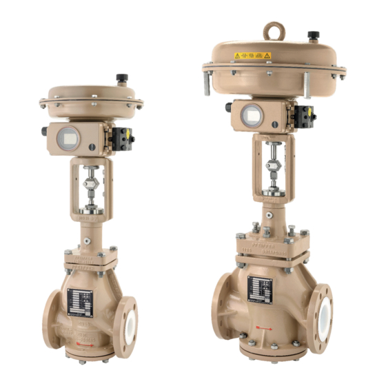
Control valve BR 01a • DIN and ANSI version
to combine with actuators
March 2023 edition
PFEIFFER Chemie-Armaturenbau GmbH · Hooghe Weg 41 · 47906 Kempen · Germany
Phone: +49 2152 2005-0 · Fax: +49 2152 1580
sales-pfeiffer-de@samsongroup.com · www.pfeiffer-armaturen.com
Advertisement
Table of Contents

Related Manuals for Samson EB 01a


Summary of Contents for Samson EB 01a
- Page 1 MOUNTING AND OPERATING INSTRUCTIONS EB 01a Translation of the original manual Control valve BR 01a • DIN and ANSI version to combine with actuators March 2023 edition PFEIFFER Chemie-Armaturenbau GmbH · Hooghe Weg 41 · 47906 Kempen · Germany Phone: +49 2152 2005-0 · Fax: +49 2152 1580...
- Page 2 Note regarding this installation and operating manual This Installation and Operating Manual (EB) provides guidance for safe assembly and operation. The notes and instructions in this EB are binding when handling PFEIFFER devices. The fi gures and illustrations in this EB are examples and must therefore be considered as such.
-
Page 3: Table Of Contents
Lifting Storing the valve Installation Installation conditions Preparing for assembly Assembling the valve and actuator 5.3.1 Travel adjustment with separately supplied SAMSON actuator Installing the valve in the pipe 5.4.1 General 5.4.2 Installing the valve Checking the assembled valve 5.5.1 Functional check 5.5.2... - Page 4 Content Start-up Operation Malfunction Detecting and rectifying errors Carrying out emergency measures Servicing Periodic tests Maintenance work 9.2.1 Replacing the seat and plug Ordering spare parts and consumables 10 Decommissioning 10-1 11 Removal 11-1 11.1 Removing the valve from the pipe 11-1 11.2 Disassembling the actuator...
-
Page 5: Safety Instructions And Safety Measures
ature range for these valves TB 01a. and is indicated on the type plate of SAMSON actuators, see − The safety regulations that apply to the pipe system in which the actuator documentation. the valves are installed and to the control system to which the −... -
Page 6: Notes Regarding Possible Severe Personnel Injury
Safety instructions and safety measures − A actuator unit that is subsequently installed on the valve is 1.1 Notes regarding possible severe adapted to the valve and is correctly adjusted in the end po- personnel injury sitions, and in particular in the closed position of the valve. −... -
Page 7: Notes Regarding Possible Property Damage
Valves that are equipped with preloaded actuator springs are un- NOTE der mechanical tension. These valves, in combination with the pneumatic SAMSON actuators, can be identifi ed by the elon- Damage to the valve due to contamination! gated screws on the bottom of the actuator. -
Page 8: Warning Notes On The Device
Safety instructions and safety measures NOTE Damage to the valve due to unsuitable lubricants! Unsuitable lubricants can corrode and damage the surface. The valve material requires suitable lubricants, see Chapter “15.1.2 Lubricants”. 1.4 Warning notes on the device Warning of moving parts Bild 1-1: Warning of moving parts There is a danger of crushing due to the lifting movements of the... -
Page 9: Markings On The Device
Markings on the device Markings on the device Each valve using has the following marking. Table 2-1: Marking on the type plate and on the body of the valve Pos. Marking Remark Manufacturer PFEIFFER Address see Chapter “15.3 Service” Valve type BR (and number value) e.g. -
Page 10: Type Plates
Markings on the device 2.1 Type plates 2.1.1 Valve type plate Figure 2-1: Marking positions of the type plate on the valve BR 01a 2.1.2 Actuator type plate See the corresponding actuator documentation. 2.2 Material marking The valves are marked on the body with material specifi cation, see Table 2-1. -
Page 11: Design And Principle Of Operation
Operating elements and functions The BR 01a valve can be selected in the following versions: − With a pneumatic SAMSON actuating drive. EB 01a_EN March 2023 edition Subject to technical changes... - Page 12 Design and principle of operation Figure 3-1: Cross-section of a DIN valve, DN 25 ... 150 Table 3-1: Parts list Item Designation Item Designation Valve body Bordered fl ange Bonnet fl ange Washer O-ring Bushing Seat Grooved pin Spacer Locking screw Washer Washer Inlay...
-
Page 13: Attachments
Design and principle of operation 3.3 Attachments NOTE The following accessories are available either individually or in Damage to the valve due to cold welding of the screws in the combinations: body! − Positioner PFEIFFER recommends a heavy-duty grease paste (e.g. Gleitmo −... - Page 14 Design and principle of operation 3.5.1.3 Assembling the bonnet fl ange NOTE − When assembling the bonnet fl ange and all other parts in Damage to the valve due to incorrect tightening torques! contact with media, only use water-free grease (e.g. halocar- The permissible torques for assembly and for retightening the bon grease).
-
Page 15: Assembling The Din Valve, Dn 200
Design and principle of operation NOTE Change the position of the plug by tightening the screws! Make sure that the position of the plug remains central. Damage to the plug, seat or guide due to clamping of the stem! Press on the stem (16) during the screwdriving process to test its smooth movement. - Page 16 Design and principle of operation Figure 3-3: Cross-section of a DIN valve, DN 200 Table 3-2: Parts list Item Designation Item Designation Valve body Spring washer Bonnet fl ange Locking screw O-ring Stuffi ng box Seat Bearing bushing Spacer O-ring Washer Guide bushing Thrust washer...
- Page 17 Design and principle of operation NOTE Info Do not screw the stuffi ng box (27) into the bonnet fl ange as far Damage to the valve due to incorrect tightening torques! as it will go. The permissible torques for assembly and for retightening the connection of the bottom fl...
-
Page 18: Assembling Ansi Valve Nps 1 To 3 And Din Valve Dn 25 To 80 [Edition 2022]
Design and principle of operation NOTE Depending on the temperature, it may be necessary to shrink the Change the position of the plug by tightening the screws! O-ring with cold spray or by cooling it down in the refrigerator. Make sure that the position of the plug remains central. Damage to the stem due to twisting! Insert the seat (4) into the body. - Page 19 Design and principle of operation Figure 3-5: Cross-section of an ANSI valve, NPS 1 to 3 Table 3-3: Parts list Item Designation Item Designation Valve body O-ring Bonnet fl ange Thrust washer O-ring Grooved pin Seat Locking screw Spacer Stuffi ng box Washer Bearing bushing Thrust washer...
- Page 20 Design and principle of operation Strike the grooved pin (23). Info Insert the preassembled stem unit, see Chapter 3.5.3.2, in the To make it easy to push on the plug stem, a small notch is made bonnet fl ange and press the fl ange of the bellows into the in the bellows to let air escape.
-
Page 21: Assembling The Ansi Valve, Nps4 To 6
Design and principle of operation Apply Loctite 668 onto the thread of the stuffi ng box (27). NOTE Screw the stuffi ng box (27) into the bonnet fl ange. Damage to the valve due to incorrect tightening torques! The permissible torques for assembly and for retightening the Info connection of the bottom fl... - Page 22 Design and principle of operation Figure 3-7: Cross-section of an ANSI valve, NPS4 ... 6 Table 3-4: Parts list Item Designation Item Designation Valve body Bordered fl ange Bonnet fl ange Washer O-ring Bushing Seat Grooved pin Spacer Locking screw Washer Washer Inlay...
-
Page 23: Assembling The Ansi Valve, Nps8
Design and principle of operation Position the washer (25). NOTE Insert the packing rings (26) with a special pin into the cover. Damage to the bonnet fl ange due to improper handling! Do not damage the bonnet fl ange, especially the thread on NOTE the stem end. - Page 24 Design and principle of operation Clean the PTFE lining of the body with detergent. Info Lay the PTFE O-ring (3) into the groove of the body. To make it easy to push on the plug stem, a small notch is made in the bellows to let air escape.
- Page 25 Design and principle of operation Figure 3-9: Cross-section of an ANSI valve, NPS8 Table 3-5: Parts list Item Designation Item Designation Valve body Spring washer Bonnet fl ange Locking screw O-ring Stuffi ng box Seat Bearing bushing Spacer O-ring Washer Guide bushing Thrust washer V-ring packing...
- Page 26 Design and principle of operation NOTE Info Do not tighten the stuffi ng box, the distance between the collar of Damage to the guide bushing due to improper assembly! the stuffi ng box and the bonnet fl ange must be 3 mm! The guide bushing must not be inserted at a slanted angle when screw it into the bonnet fl...
-
Page 27: Shipment And On-Site Transport
Damage to the valve due to improper fastening of the sling! Check the scope of supply. Compare the delivered goods The welded-on lifting eyes on SAMSON actuators are used only with the delivery note. for actuator assembling and disassembling as well as for lifting Check the supply for transport damage. - Page 28 Shipment and on-site transport Figure 4-1: Schematic drawing of the lifting points on the valve Conditions for lifting DANGER Use a hook with a safety clamp as the suspension element so that the sling cannot slip off the hook during lifting and Danger due to incorrect lifting and transport! transport, see Figure 4-1.
-
Page 29: Storing The Valve
Shipment and on-site transport Move the valve at a constant speed to the installation site. The valve must be stored in its protective packaging and/or with the protective caps on the connection ends. Install the valve in the pipe, see chapter 5.4. The packaging should protect the scratch-sensitive plastic After installation in the pipe: check that the fl... - Page 30 Shipment and on-site transport EB 01a_EN March 2023 edition Subject to technical changes...
-
Page 31: Installation
Installation Venting Installation Vents are screwed into the exhaust air connections of pneumatic The work described in this chapter may only be performed by and electropneumatic devices to ensure that the generated ex- specialist personnel qualifi ed to perform the corresponding task. haust air can be released to the outside (protection against over- The following instructions apply additionally for valves. -
Page 32: Travel Adjustment With Separately Supplied Samson Actuator
• • Damage to the valve due to incorrect travel adjustment! 350v2 cm • • • SAMSON If a SAMSON actuator is retrofi tted, a preadjustment of the travel 355v2 cm • • • actuator is necessary: 700 cm •... -
Page 33: Installing The Valve In The Pipe
Installation Details about the other actuators can also be found in the corre- The connection ends of the pipes must align with the valve sponding actuator documentation. connections and have plane-parallel ends. Connection fl ang- es that are not plane parallel can damage the PTFE lining during installation! The dimensions provided in Table 5-3 reach a suitable pretension The connection data for the actuator unit must match the con-... -
Page 34: Installing The Valve
Installation 5.4.2 Installing the valve WARNING Close the valve in the pipe for the duration of the installation. Danger due to improperly executed control commands! Remove the protective caps on the valve openings prior to in- Incorrectly executed control commands can cause serious injuries stallation. -
Page 35: Start-Up
Start-up If required, retighten the screw connection of the body parts, Start-up see Table 15-1 to Table 15-4 in Chapter “15.1.1 Tightening The work described in this chapter may only be performed by torques”. specialist personnel qualifi ed to perform the corresponding task. Open the valve slowly in the pipe. - Page 36 Start-up EB 01a_EN March 2023 edition Subject to technical changes...
-
Page 37: Operation
Operation − Valves with a bellows generally have a test connection Operation (e.g. ¼“) between the bellows and the outer stem sealing. As soon as the commissioning/recommissioning work is This makes it possible to check if the bellows is not damaged. complete, see Chapter “6 Start-up”, the valve is ready for −... - Page 38 Operation EB 01a_EN March 2023 edition Subject to technical changes...
-
Page 39: Malfunction
Malfunction Malfunction When rectifying the faults, chapter “1 Safety instructions and safety measures” must be observed. 8.1 Detecting and rectifying errors Type of fault Possible cause Measure Leaks in the pipe connection The fl ange connection of the Tighten the fl ange screws. lined valve is leaky NOTE An excessive tightening torque when retightening the fl... - Page 40 Malfunction Type of fault Possible cause Measure Leaks in the stem sealing Medium escapes from the If the valve on the stuffi ng box is leaky, the bellows is defective. stuffi ng box DANGER Danger of injury due to hazardous media! It must be kept in mind that the media is usually hazardous.
-
Page 41: Carrying Out Emergency Measures
Malfunction 8.2 Carrying out emergency measures In the case of a power supply failure, the valve automatically switches to the preset fail-safe position, (see “Fail-safe positions” in Chapter “3 Design and principle of operation”. The system operator is responsible for emergency measures. In case of a valve fault: −... - Page 42 Malfunction EB 01a_EN March 2023 edition Subject to technical changes...
-
Page 43: Servicing
Servicing Servicing NOTE The work described in this chapter may only be performed by Damage to the valve due to excessively high or low tightening specialist personnel qualifi ed to perform the corresponding task. torques! The following documents are required in addition for the mainte- The valve components must be tightened with specifi... -
Page 44: Maintenance Work
Servicing 9.3 Ordering spare parts and consumables Measures in the case of a negative Test test result Information about spare parts, lubricants and tools can be re- Check the lifting movement of Tighten the packing correctly. ceived from the After Sales Service at PFEIFFER. the actuator stem and stem for If the actuator stem and stem are linear, smooth movement. -
Page 45: Decommissioning
Decommissioning 10 Decommissioning The work described in this chapter may only be performed by specialist personnel qualifi ed to perform the corresponding task. WARNING Danger of burning due to hot or cold components and pipe! Valve components and pipes can become very hot or very cold during operation and cause burns upon contact. - Page 46 Decommissioning EB 01a_EN 10-2 March 2023 edition Subject to technical changes...
-
Page 47: Removal
Do not loosen the test connection while the valve is pressur- ised. Danger of injury due to prestressed springs! SAMSON actuators with preloaded actuator springs are pressurised. These actuators can be identifi ed by the elongat- ed screws on the bottom of the actuator. - Page 48 Removal EB 01a_EN 11-2 March 2023 edition Subject to technical changes...
-
Page 49: Repairs
Repairs Release the stuffi ng box (27) and screw it out of the bonnet 12 Repairs fl ange. If the valve no longer works properly or if it does not work at all, Remove the graphite packing (26) or the PFFE V-ring packing it is defective and must be repaired or replaced. - Page 50 Repairs Figure 12-2: Section diagram of valve BR 01a EB 01a_EN 12-2 March 2023 edition Subject to technical changes...
-
Page 51: Replacing The Seat
Repairs Table 12-1: Parts list Item Designation Item Designation Item Designation Item Designation Valve body Grooved pin Set of spring washers Bonnet fl ange Plug Screw plug O-ring O-ring Cord Washer Screw Seat Bellows Packing Spacer Stem Stuffi ng box Yoke Washer Bordered fl... -
Page 52: Sending Devices To Pfeiffer
Repairs 12.7 Sending devices to PFEIFFER Defective valves can be sent to PFEIFFER for repair. Proceed as follows to send devices: WARNING Danger due to a contaminated valve! When returning a used valve to the manufacturer for service, decontaminate the valve properly in advance. When returning a used valve, include the safety data sheet for the medium as well as confi... -
Page 53: Disposal
Disposal 13 Disposal For disposal, observe the local, national and international regulations. Do not dispose of old components, lubricant and hazardous materials with domestic waste. EB 01a_EN 13-1 March 2023 edition Subject to technical changes... - Page 54 Disposal EB 01a_EN 13-2 March 2023 edition Subject to technical changes...
-
Page 55: Certifi Cates
Certifi cates 14 Certifi cates The declaration of conformity is available on the following pages: − Declaration of conformity according to Pressure Equipment Directive 2014/68/EU for automated valves, see page 14-2. − Declaration of conformity according to Pressure Equipment Directive 2014/68/EU for manually operated valves, see page 14-3. - Page 56 Certifi cates EB 01a_EN 14-2 March 2023 edition Subject to technical changes...
- Page 57 Certifi cates EB 01a_EN 14-3 March 2023 edition Subject to technical changes...
- Page 58 Certifi cates EB 01a_EN 14-4 March 2023 edition Subject to technical changes...
- Page 59 Certifi cates EB 01a_EN 14-5 March 2023 edition Subject to technical changes...
- Page 60 Certifi cates EB 01a_EN 14-6 March 2023 edition Subject to technical changes...
-
Page 61: Annex
Annex Table 15-5: Tightening values of the support bolts on the DIN 15 Annex version DN [mm] 15.1 Tightening torques, lubricant and tools MA [Nm] Table 15-6: Tightening values of the support bolts on the ANSI 15.1.1 Tightening torques version NPS [inch] Info MA [Nm]... - Page 62 Annex 15.2.1 Spare parts for DIN-Valves, DN 25 ... 50 Figure 15-1: Exploded drawing of a DIN-Valve, DN 25 ... 50 EB 01a_EN 15-2 March 2023 edition Subject to technical changes...
- Page 63 Annex Table 15-10: Recommended spare parts for a DIN-Valve, DN 25 ... 50 In the spare parts set Included in the set of In the spare parts for Item Designation Material for commissioning seals 2 year operation Valve body EN-JS 1049 / PTFE Bonnet fl...
-
Page 64: Spare Parts For Din-Valves, Dn 25
Annex 15.2.2 Spare parts for DIN-Valves, DN 80 ... 150 Figure 15-2: Exploded drawing of a DIN-Valve, DN 80 ... 150 EB 01a_EN 15-4 March 2023 edition Subject to technical changes... - Page 65 Annex Table 15-11: Recommended spare parts for a DIN-Valve, DN 80 ... 150 In the spare parts set Included in the set of In the spare parts for Item Designation Material for commissioning seals 2 year operation Valve body EN-JS 1049 / PTFE Bonnet fl...
-
Page 66: Spare Parts For Din-Valves, Dn 200
Annex 15.2.3 Spare parts for DIN-Valves, DN 200 Figure 15-3: Exploded drawing of a DIN-Valve, DN 200 EB 01a_EN 15-6 March 2023 edition Subject to technical changes... - Page 67 Annex Table 15-12: Recommended spare parts for a DIN-Valve, DN 200 In the spare parts set Included in the set of In the spare parts for Item Designation Material for commissioning seals 2 year operation Valve body EN-JS 1049 / PTFE Bonnet fl...
-
Page 68: Spare Parts For Ansi-Valves, Nps1
Annex 15.2.4 Spare parts for ANSI-Valves, NPS1 ... 3 and DIN-Valves, DN 25 ... 80 [Edition 2022] Figure 15-4: Exploded drawing of a ANSI-Valve, NPS1 ... 3 EB 01a_EN 15-8 March 2023 edition Subject to technical changes... - Page 69 Annex Table 15-13: Recommended spare parts for a ANSI-Valve, NPS1 ... 3 In the spare parts set Included in the set of In the spare parts for Item Designation Material for commissioning seals 2 year operation Valve body A395 / PTFE Bonnet fl...
-
Page 70: Spare Parts For Ansi-Valves, Nps4
Annex 15.2.5 Spare parts for ANSI-Valves, NPS4 ... 6 Figure 15-5: Exploded drawing of a ANSI-Valve, NPS4 ... 6 EB 01a_EN 15-10 March 2023 edition Subject to technical changes... - Page 71 Annex Table 15-14: Recommended spare parts for a ANSI-Valve, NPS4 ... 6 In the spare parts set Included in the set of In the spare parts for Item Designation Material for commissioning seals 2 year operation Valve body A395 / PTFE Bonnet fl...
-
Page 72: Spare Parts For Ansi-Valves, Nps8
Annex 15.2.6 Spare parts for ANSI-Valves, NPS8 Figure 15-6: Exploded drawing of a ANSI-Valve, NPS8 EB 01a_EN 15-12 March 2023 edition Subject to technical changes... - Page 73 Annex Table 15-15: Recommended spare parts for a ANSI-Valve, NPS8 In the spare parts set Included in the set of In the spare parts for Item Designation Material for commissioning seals 2 year operation Valve body A395 / PTFE Bonnet fl ange A395 1049 O-ring PTFE...
-
Page 74: Service
Annex 15.3 Service For maintenance and repair work as well as malfunctions or de- fects, contact the After Sales Service at PFEIFFER for support. E-mail The After Sales Service can be reached at the e-mail address “sales-pfeiffer-de@samsongroup.com”. Necessary data Provide the following information in the case of questions and for troubleshooting: −... - Page 75 EB 01a_EN March 2023 edition Subject to technical changes...
- Page 76 PFEIFFER Chemie-Armaturenbau GmbH Hooghe Weg 41 · 47906 Kempen · Germany Telefon: +49 2152 2005-0 · Telefax: +49 2152 1580 E-Mail: sales-pfeiffer-de@samsongroup.com · Internet: www.pfeiffer-armaturen.com EB 01a_EN March 2023 edition Subject to technical changes...
Need help?
Do you have a question about the EB 01a and is the answer not in the manual?
Questions and answers