Table of Contents
Advertisement
Quick Links
MOUNTING AND
OPERATING INSTRUCTIONS
EB 20b
Translation of the original manual
Ball valve BR 20b DIN and ANSI version
to combine with actuators
February 2022 edition
PFEIFFER Chemie-Armaturenbau GmbH · Hooghe Weg 41 · 47906 Kempen · Germany
Phone: +49 2152 2005-0 · Fax: +49 2152 1580
sales-pfeiffer-de@samsongroup.com · www.pfeiffer-armaturen.com
Advertisement
Table of Contents

Related Manuals for Samson EB 20b


Summary of Contents for Samson EB 20b
- Page 1 MOUNTING AND OPERATING INSTRUCTIONS EB 20b Translation of the original manual Ball valve BR 20b DIN and ANSI version to combine with actuators February 2022 edition PFEIFFER Chemie-Armaturenbau GmbH · Hooghe Weg 41 · 47906 Kempen · Germany Phone: +49 2152 2005-0 · Fax: +49 2152 1580...
- Page 2 Note regarding this installation and operating manual This Installation and Operating Manual (EB) provides guidance for safe assembly and operation. The notes and instructions in this EB are binding when handling PFEIFFER devices. The fi gures and illustrations in this EB are ex- amples and must therefore be considered as such.
-
Page 3: Table Of Contents
Content Content Safety instructions and safety measures Notes regarding possible severe personnel injury Notes regarding possible personnel injury Notes regarding possible property damage Warning notes on the device Markings on the device Type plates 2.1.1 Ball valve type plates 2.1.2 Actuator type plate Material marking Design and principle of operation... - Page 4 Content Start-up Operation Malfunction Detecting and rectifying errors Carrying out emergency measures Servicing Periodic tests Maintenance work 9.2.1 Replacing the seal rings and ball Ordering spare parts and consumables 10 Decommissioning 10-1 11 Removal 11-1 11.1 Removing the ball valve from the pipe 11-1 11.2 Disassembling the actuator...
-
Page 5: Safety Instructions And Safety Measures
Safety instructions and safety measures pressurised pipes who are familiar with the assembly, commis- Safety instructions and safety measures sioning and operation of this product. − Specialist personnel in terms of this installation and operating Intended use manual are persons who, on the basis of their vocational ed- The PFEIFFER ball valve BR 20b is manually operated in combi- ucation, knowledge and experience and knowledge of the nation with an actuator for the regulation of the volume fl... -
Page 6: Notes Regarding Possible Severe Personnel Injury
Safety instructions and safety measures − The ball valve is only used as intended as described in this 1.1 Notes regarding possible severe per- chapter. sonnel injury − An actuator unit that is subsequently installed on the ball valve is adapted to it and the max. torque is observed, and is DANGER correctly adjusted in the end positions, and in particular in the opening position of the ball valve. -
Page 7: Notes Regarding Possible Property Damage
Safety instructions and safety measures WARNING WARNING Danger of crushing due to moving parts! Deviation of the breakaway and actuating forces due to The ball valve contains moving parts (actuator and switching non-actuation of the ball valve! shaft as well as the hand lever) that can lead to crushing if reach- Depending on the period of time of non-actuation, the breaka- ing into it. -
Page 8: Warning Notes On The Device
Safety instructions and safety measures Instructions for retightening the body screws NOTE Damage to the ball valve due to an impermissible pressure in- crease! The ball valve body may contain small amounts of medium in the closed and open position. Use a ball valve with an optional relief bore if it is possible that the closed area of the ball fi... -
Page 9: Markings On The Device
Markings on the device Markings on the device Each ball valve usually has the following marking. Table 2-1: Marking on the type plate and on the body of the valve Pos. Marking Remark Manufacturer PFEIFFER Address see Chapter “15.4 Service” Valve type BR (and number value) e.g. -
Page 10: Type Plates
Markings on the device 2.1 Type plates 2.1.1 Ball valve type plates Figure 2-1: Type plate (82150ae) for DN 15 ... 25 and NPS½ ... 1 Figure 2-2: Type plate (82149ae) for DN 40 ... 200 and NPS1½ ... 8 2.1.2 Actuator type plate See the corresponding actuator documentation. -
Page 11: Design And Principle Of Operation
Design and principle of operation − Use as a control ball valve with calibrated seat ring Design and principle of operation (≤ DN 100) − PFA-conductive lining Function and principle of operation − Stainless steel heat pack The media can fl ow in both directions through the BR 20b ball valve with full passage. -
Page 12: Technical Data
Design and principle of operation 3.4 Technical data Info The type plates of the ball valve and actuator offer information The seal rings may not be installed without clearance. To achieve about the valve version, see Chapter “2 Markings on the device”. the tightness of the ball valve, the seal rings must be installed in their seat with suffi... - Page 13 Design and principle of operation Figure 3-1: Sectional drawing of the ball valve in the DIN version, DN 15 ... 100 Table 3-1: Parts list of the ball valve in the DIN version, DN 15 ... 100 Pos. Designation Pos. Designation Main body with lining Screw...
-
Page 14: Assembly Of The Din Ball Valve, Dn 25
Design and principle of operation Tighten the screws evenly in a criss-cross pattern until a gap Preassembly of the ball valve with the two-part ball/switching between 1 - 2 mm has formed between the stuffi ng box shaft fl ange and the body. Insert the switching shaft (20) tilted into the packing space. -
Page 15: Assembly Of The Din Ball Valve, Dn 150
Design and principle of operation Place the V-ring packing (5) in the PTFE bushing (17). The ar- Info rangement and quantity of the V-rings can be found on the Push the bottom ring in with more force, therefore use a suitable drawing, see Figure 3-2. - Page 16 Design and principle of operation Figure 3-2: Sectional drawing of the ball valve in the DIN version, DN 150 ... 200 Table 3-2: Parts list of the ball valve in the DIN version, DN 150 ... 200 Pos. Designation Pos. Designation Body with lining Screw / stud bolt...
-
Page 17: Assembly Of The Ansi Ball Valve
Design and principle of operation Fasten the body halves together with screws (10), washers 3.5.4 Assembly of the ANSI ball valve (12) and nuts (11) so they are hand-tight. 3.5.4.1 Assembly of the body halves Info Place both body halves (1 and 2) with the fl ange facing −... - Page 18 Design and principle of operation Figure 3-3: Sectional drawing of the ball valve in the ANSI version Table 3-3: Parts list of the ball valve in the ANSI version Pos. Designation Pos. Designation Main body with lining Screw / stud bolt Body with lining Ball with coating Washer...
- Page 19 Design and principle of operation Tighten the screws (10) and nuts (11) on the body halves (1 3.5.4.2 Final assembly of the ball valve and 2). Place the second body half onto the previously described body half, so that it centres itself on the ball stem and the Info V-ring packing as well as the seal ring.
- Page 20 Design and principle of operation EB 20b_EN 3-10 February 2022 edition Subject to technical changes...
-
Page 21: Shipment And On-Site Transport
Shipment and on-site transport Shipment and on-site transport WARNING The work described in this chapter may only be performed by Overturning of the lifting equipment and damage to the load specialist personnel qualifi ed to perform the corresponding task. lifting equipment by exceeding the lifting capacity! −... -
Page 22: Lifting Points On The Body
Shipment and on-site transport Figure 4-1: Lifting points on the ball valve Conditions for lifting 4.3.3 Lifting points on the body Use a hook with a safety clamp as the suspension element so Fasten a lifting sling to each fl ange of the housing and on the that the sling cannot slip off the hook during lifting and trans- suspension element (e.g. -
Page 23: Storing The Ball Valve
Shipment and on-site transport Lift the ball valve carefully. Check if the load lifting equipment holds. Move the ball valve at a constant speed to the installation site. Install the ball valve in the pipe, see chapter 5.4 After installation in the pipe: check that the fl anges are fi rmly tightened and that the ball valve holds in the pipe. - Page 24 Shipment and on-site transport EB 20b_EN February 2022 edition Subject to technical changes...
-
Page 25: Installation
Installation Venting Installation Vents are screwed into the exhaust air connections of pneumatic The work described in this chapter may only be performed by and electropneumatic devices to ensure that the generated ex- specialist personnel qualifi ed to perform the corresponding task. haust air can be released to the outside (protection against over- The following instructions apply additionally for ball valves. -
Page 26: Installing The Ball Valve In The Pipe
Installation The ball valve can be used in both directions if a direction ar- WARNING row is not applied. Danger and damage due to use of an electrical actuator! DANGER Make sure that the actuator in the end positions is turned off by the limit switch signal. -
Page 27: Installing The Ball Valve
Installation Carry out venting on the side that faces away from the work- 5.4.3 Installation instructions for lined gate ing area of operating personnel. ball valves with heat pack When installing peripheral devices, make sure that they can be operated from the working area of operating personnel. Info When installing the lined ball valves with heat packs in the pipe, a corresponding straight outlet pipe section must be included. -
Page 28: Pressure Test Of The Pipe Section
Installation If the actuator- and switching shaft are blocked (e.g. due to 5.5.3 Swivelling movement “seizure” if not actuated for a long period of time”), release The rotary movement of the actuator- and switching shaft must be the residual energy of the actuator (spring tension) before re- linear without any jerky movements. -
Page 29: Start-Up
Start-up Commissioning/recommissioning Start-up The PFA plastic sealing surfaces tend to fl ow. After commis- The work described in this chapter may only be performed by sioning and reaching the operating temperature, tighten all specialist personnel qualifi ed to perform the corresponding task. fl... - Page 30 Start-up EB 20b_EN February 2022 edition Subject to technical changes...
-
Page 31: Operation
Operation − For the manual operation or manual override of the actuator Operation (if present), normal manual forces are suffi cient and the use As soon as the commissioning/recommissioning work is com- of extensions to increase the actuation torque is not permit- plete, see Chapter “6 Commissioning”, the ball valve is ready for ted. - Page 32 Operation EB 20b_EN February 2022 edition Subject to technical changes...
-
Page 33: Malfunction
Malfunction Malfunction When rectifying the faults, chapter “1 Safety instructions and safety measures” must be observed. 8.1 Detecting and rectifying errors Type of fault Possible cause Measures Leaks in the pipe connection The fl ange connection of the Tighten the fl ange screws. lined ball valve is leaky NOTE An excessive tightening torque when retightening the fl... -
Page 34: Carrying Out Emergency Measures
Malfunction Type of fault Possible cause Measures Malfunction The actuator unit or control Check the actuator unit and control command. does not react The actuator and control are Remove and inspect the valve, see chapter “1 Safety instructions and safety measures”. Remove the actuator unit and measure and check the ball valve torque. -
Page 35: Servicing
Servicing Servicing NOTE The work described in this chapter may only be performed by Damage to the ball valve due to excessively high or low tight- specialist personnel qualifi ed to perform the corresponding task. ening torques! The following documents are required in addition for the mainte- The ball valve components must be tightened with specifi... -
Page 36: Maintenance Work
Servicing Measures in the case of a negative Test test result Check the rotary movement of If the actuator- and switching shaft the actuator- and switching are blocked, remove the blockage. shaft for smooth movement. WARNING! If the actuator- and switching shaft are blocked (e.g. -
Page 37: Decommissioning
Decommissioning Observe the following points during decommissioning: 10 Decommissioning To decommission the ball valve for maintenance and repair work The work described in this chapter may only be performed by or for disassembly, perform the following steps: specialist personnel qualifi ed to perform the corresponding task. Close the valves upstream and downstream of the ball valve so that no medium fl... - Page 38 Decommissioning EB 20b_EN 10-2 February 2022 edition Subject to technical changes...
-
Page 39: Removal
Removal 11 Removal 11.1 Removing the ball valve from the pipe The work described in this chapter may only be performed by Loosen the fl ange connection. specialist personnel qualifi ed to perform the corresponding task. Remove the ball valve from the pipe, see Chapter “4.3 Trans- porting and lifting the ball valve”. - Page 40 Removal EB 20b_EN 11-2 February 2022 edition Subject to technical changes...
-
Page 41: Repairs
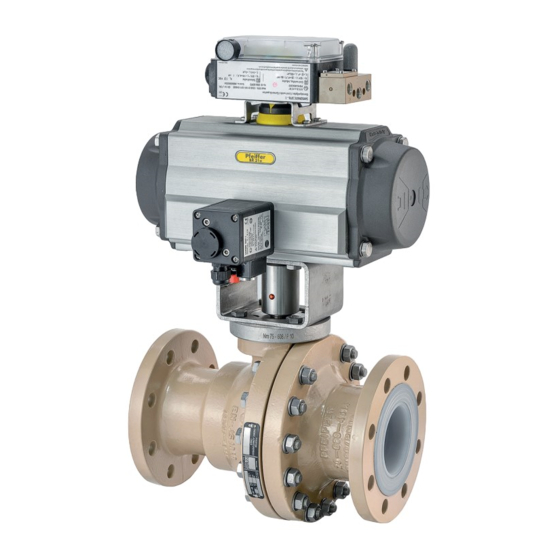
Repairs 12 Repairs 12.2 Replacing the V-ring packing in the case of a DIN ball valve, DN 150 ... 200 If the ball valve no longer works properly or if it does not work at all, it is defective and must be repaired or replaced. If a leak is found in the stuffi... - Page 42 Repairs Figure 12-1: BR 20b ball valve EB 20b_EN 12-2 February 2022 edition Subject to technical changes...
-
Page 43: Additional Repairs
Repairs Table 12-1: Parts list Pos. Designation Pos. Designation Main body with lining Washer Body with lining Bush Ball with coating Bush Seat ring Spring washer V-ring packing Bush Stuffi ng box fl ange Center ring Bearing bush Lever Set of spring washers Shaft Screw Screw / stud bolt... - Page 44 Repairs EB 20b_EN 12-4 February 2022 edition Subject to technical changes...
-
Page 45: Disposal
Disposal 13 Disposal For disposal, observe the local, national and international regulations. Do not dispose of old components, lubricant and hazardous materials with domestic waste. EB 20b_EN 13-1 February 2022 edition Subject to technical changes... - Page 46 Disposal EB 20b_EN 13-2 February 2022 edition Subject to technical changes...
-
Page 47: Certifi Cates
Certifi cates 14 Certifi cates The declaration of conformity is available on the following pages: − Declaration of conformity according to Pressure Equipment Directive 2014/68/EU for automated valves, see page 14-2. − Declaration of conformity according to Pressure Equipment Directive 2014/68/EU for manually operated valves, see page 14-3. - Page 48 Certifi cates EB 20b_EN 14-2 February 2022 edition Subject to technical changes...
- Page 49 Certifi cates EB 20b_EN 14-3 February 2022 edition Subject to technical changes...
- Page 50 Certifi cates EB 20b_EN 14-4 February 2022 edition Subject to technical changes...
- Page 51 Certifi cates EB 20b_EN 14-5 February 2022 edition Subject to technical changes...
- Page 52 Certifi cates EB 20b_EN 14-6 February 2022 edition Subject to technical changes...
-
Page 53: Annex
Annex Table 15-1: Tightening torques for body connections 15 Annex Nominal size Connection Tightening torque 15.1 Tightening torques, lubricant and tools DN 15 1 to 4 25 Nm 1 to 6 25 Nm DN 25 / NPS1 15.1.1 Tightening torques 7 to 8 35 Nm 1 to 7... -
Page 54: Lubricant
Annex 15.1.2 Lubricant Table 15-4: Recommended lubricant Temperature range Lubricant Screws and nuts -10 ... +200°C Microgleit, GP350 Not suitable for grease-free ball valves or for use with oxygen Stem sealing -10 ... +200°C Water-free grease (e.g. halo- and parts in carbon TM) contact with me- 15.1.3 Tools... -
Page 55: Spare Parts Of The Ball Valve In The Din Version, Dn
Annex 15.2.1 Spare parts of the ball valve in the DIN version, DN 15 Figure 15-2: Exploded drawing of the ball valve in the DIN version, DN 15 Table 15-5: Recommend spare parts for the ball valve in the DIN version, DN 15 In the spare parts set for In the spare parts for 2 year Pos. -
Page 56: Spare Parts Of The Ball Valve In The Din Version, Dn 25
Annex 15.2.2 Spare parts of the ball valve in the DIN version, DN 25 ... 100 Figure 15-3: Exploded drawing of the ball valve in the DIN version, DN 25 ... 100 Table 15-6: Recommend spare parts for the ball valve in the DIN version, DN 25 ... 100 In the spare parts set for In the spare parts for 2 year Pos. -
Page 57: Spare Parts Of The Ball Valve In The Din Version, Dn 150
Annex 15.2.3 Spare parts of the ball valve in the DIN version, DN 150 ... 200 Figure 15-4: Exploded drawing of the ball valve in the DIN version, DN 150 ... 200 Table 15-7: Parts list of the ball valve in the DIN version, DN 150 ... 200 In the spare parts set for In the spare parts for 2 year Pos. -
Page 58: Spare Parts Of The Ball Valve In The Ansi Version, Nps½
Annex 15.2.4 Spare parts of the ball valve in the ANSI version, NPS½ ... 8 Figure 15-5: Exploded drawing of the ball valve in the ANSI version, NPS½ ... 8 Table 15-8: Parts list of the ball valve in the ANSI version, NPS½ ... 8 In the spare parts set for In the spare parts for 2 year Pos. -
Page 59: Service
Annex 15.3 Service For maintenance and repair work as well as malfunctions or de- fects, contact the After Sales Service at PFEIFFER for support. E-mail The After Sales Service can be reached at the e-mail address sales-pfeiffer-de@samsongroup.com. Necessary data Provide the following information in the case of questions and for troubleshooting: −... - Page 60 Annex EB 20b_EN 15-8 February 2022 edition Subject to technical changes...
- Page 61 EB 20b_EN February 2022 edition Subject to technical changes...
- Page 62 EB 20b_EN February 2022 edition Subject to technical changes...
- Page 63 EB 20b_EN February 2022 edition Subject to technical changes...
- Page 64 PFEIFFER Chemie-Armaturenbau GmbH Hooghe Weg 41 · 47906 Kempen · Germany Phone: +49 2152 2005-0 · Fax: +49 2152 1580 E-Mail: sales-pfeiffer-de@samsongroup.com · Internet: www.pfeiffer-armaturen.com EB 20b_EN February 2022 edition Subject to technical changes...
Need help?
Do you have a question about the EB 20b and is the answer not in the manual?
Questions and answers