Table of Contents
Advertisement
Quick Links
Advertisement
Table of Contents

Related Manuals for Samson EB 8012 EN


Summary of Contents for Samson EB 8012 EN
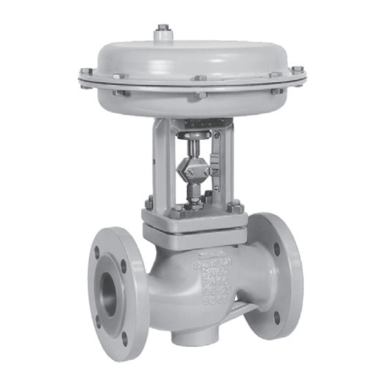
- Page 1 EB 8012 EN Translation of original instructions Type 3241 Valve with Type 3271 Actuator (left) and Type 3277 Actuator (right) Type 3241 Valve · ANSI and JIS versions In combination with an actuator, e.g. a Type 3271 or Type 3277 Pneumatic Actuator Edition November 2022...
- Page 2 Note on these mounting and operating instructions These mounting and operating instructions assist you in mounting and operating the device safely. The instructions are binding for handling SAMSON devices. The images shown in these instructions are for illustration purposes only. The actual product may vary.
-
Page 3: Table Of Contents
5.3.2 Mounting the actuator onto the valve ............5-9 5.3.3 Installing the valve into the pipeline ............5-12 Testing the installed valve ................5-12 5.4.1 Leak test ....................5-14 5.4.2 Travel motion ....................5-15 5.4.3 Fail-safe position ..................5-15 5.4.4 Pressure test ....................5-15 EB 8012 EN... - Page 4 Removal ....................11-1 11.1 Removing the valve from the pipeline ............11-2 11.2 Removing the actuator from the valve ............11-2 Repairs ....................12-1 12.1 Returning devices to SAMSON ..............12-1 Disposal ....................13-1 Certificates ....................14-1 Annex......................15-1 15.1 Tightening torques, lubricants and tools ............15-1 15.2 Spare parts ....................15-1 15.3...
-
Page 5: Safety Instructions And Measures
SAMSON. SAMSON does not assume any liability for damage resulting from the failure to use the de- vice for its intended purpose or for damage caused by external forces or any other external factors. - Page 6 (see associated actuator documentation). When the valve is combined with a SAMSON Type 3271 or Type 3277 Pneumatic Actuator, the valve moves to a certain fail- safe position (see the 'Design and principle of operation' section) upon supply air or control signal failure.
- Page 7 Start-up and shutdown procedures fall within the scope of the operator's duties and, as such, are not part of these mounting and operating instructions. SAMSON is unable to make any statements about these procedures since the operative details (e.g. differential pressures and temperatures) vary in each individual case and are only known to the operator.
- Page 8 > About SAMSON > Material Compliance > REACH If a device contains a substance listed as a substance of very high concern on the candi- date list of the REACH regulation, this is indicated on the SAMSON delivery note. EB 8012 EN...
-
Page 9: Notes On Possible Severe Personal Injury
Î Install the control valve in such a way that vent openings are not located at eye level and the actuator does not vent at eye level in the work position. Î Use suitable silencers and vent plugs. Î Wear eye protection when working in close proximity to the control valve. EB 8012 EN... - Page 10 Risk of personal injury due to preloaded springs. Valves in combination with pneumatic actuators with preloaded springs are under ten- sion. These control valves with SAMSON pneumatic actuators can be identified by the long bolts protruding from the bottom of the actuator.
-
Page 11: Notes On Possible Property Damage
Î Observe the specified tightening torques (u AB 0100). Risk of valve damage due to the use of unsuitable tools. Certain tools are required to work on the valve. Î Only use tools approved by SAMSON (u AB 0100). EB 8012 EN... -
Page 12: Notes On The Use Of An Rfid Tag
The lubricants to be used depend on the valve material. Unsuitable lubricants may cor- rode and damage surfaces. Î Only use lubricants approved by SAMSON (u AB 0100). Risk of the process medium being contaminated through the use of unsuitable lubri- cants and/or contaminated tools and components. -
Page 13: Markings On The Device
Fig. 2-3 and the inscription table list all pos- Version: sible characteristics and options that may M: mixing valve · V: diverting valve appear on a valve nameplate. Only the in- scriptions relevant to the ordered Type 3241 Valve actually appear on the nameplate. EB 8012 EN... -
Page 14: Actuator Nameplate
ST 1 to ST 3 · device's current technical data as configured MHC1: multi-hole cage · CC1: Combi Cage · ZT1: Zero Travel · by SAMSON. The material number enables LDB: Low dB you to view the device's technical data as 16 PSA version: configured by SAMSON upon delivery of the device. -
Page 15: Label When An Adjustable Packing Is Installed
Data Matrix code on the elec- tronic nameplate. It can be read using a smartphone, tablet or RFID reader. Application range according to the technical data (see the 'Design and principle of opera- tion' section). EB 8012 EN... - Page 16 EB 8012 EN...
-
Page 17: Design And Principle Of Operation
The Type 3241 Valve is a single-seated 3.1 Fail-safe action globe valve. This valve is preferably com- bined with a SAMSON Type 3271 or The fail-safe position of the control valve up- Type 3277 Pneumatic Actuator. It can also on air supply or control signal failure de- be combined with other actuators. - Page 18 Threaded bush- ing (packing nut) Stem connector nut Lock nut Spring Nuts Packing Body gasket Travel indicator scale Castellated nut Actuator A7 Actuator stem A8 Ring nut A26 Stem connector clamps Fig. 3-2: Type 3241 Valve, body NPS 8 to 12 EB 8012 EN...
-
Page 19: Versions
3.2 Versions Actuators In these instructions, the preferable combina- With insulating section/bellows seal tion with a SAMSON Type 3271 or The modular design allows an insulating sec- Type 3277 Pneumatic Actuator is described. tion or bellows seal to be fitted to the stan- The pneumatic actuator (with or without dard valve version. -
Page 20: Additional Fittings
Strainers used. The decision is based on the risk posed by the plant and its operating conditions. We recommend installing a SAMSON strainer upstream of the valve. It prevents sol- Noise reduction id particles in the process medium from Trims with flow dividers can be used to re- damaging the valve. -
Page 21: Technical Data
Design and principle of operation 3.5 Technical data Noise emissions SAMSON is unable to make general state- The nameplates on the valve and actuator ments about noise emissions. The noise emis- provide information on the control valve ver- sions depend on the valve version, plant fa- sion. - Page 22 The H2 dimension is the distance from the middle of the flow path to the bottom of the valve body. The H2 dimension in this valve is not the lowest point of the valve. This valve's lowest point is the bottom of the connecting flanges. The flange dimensions comply with the corresponding flange standard. EB 8012 EN...
- Page 23 H8 increases by 6.69“ (170 mm) for valves with C 290, 420 or 735 (K 250, 360 or 630) and 60 mm rated travel operating with overtravel Table 3-3: Weights for Type 3241 Valve ½ ¾ 1½ 2½ Valve Weight 287 1096 1892 2535 without 858 1150 actuator EB 8012 EN...
- Page 24 ≤750 cm² seal 28.07 28.11 29.72 34.53 35.94 Long Insulating 27.36 28.82 section or – H4 for 1000 cm² bellows actua- 1400- seal 60 cm² 36.85 38.31 Long – Insulating section or – 1400- bellows 120 cm²/ seal 2800 cm² Long – EB 8012 EN...
- Page 25 19.8 1400- – – H8 for 60 cm² actua- 1400- 19.8 19.8 25.6 25.6 19.8 19.8 25.6 25.6 120 cm² 2800 cm² 1191 2220 2220 2690 1312 2407 2407 2793 Weight without actuator (approx.) 1007 1007 1220 1092 1092 1267 EB 8012 EN...
- Page 26 ANSI valve versions with bellows seal, insulating section or heating jacket u T 8012-2 for JIS valve versions with bellows seal, insulating section or heating jacket The associated actuator documentation applies to actuators, e.g. SAMSON pneumatic actu- ators: u T 8310-1 for Type 3271 or Type 3277 Pneumatic Actuators up to 750 cm² actuator area u T 8310-2 for Type 3271 Actuator with 1000 cm²...
-
Page 27: Shipment And On-Site Transport
4.2 Removing the packaging valve (including actuator and packaging, from the valve if applicable). Observe the following sequence: Î Do not open or remove the packaging until immediately before lifting to install the valve into the pipeline. EB 8012 EN... -
Page 28: Transporting The Valve
Risk of personal injury due to the control A swivel hoist can be screwed into valve tipping over. SAMSON actuators with a female thread on Î Observe the valve's center of gravity. the top diaphragm case in place of the Î... -
Page 29: Lifting The Valve
(e.g. crane or forklift) to lift Fig. 4-1: Lifting points on the control valve: up to NPS 6 with flanges (left) and with welding ends (middle) · NPS 6 and larger with additional lifting eyelet on the actuator (right) EB 8012 EN... - Page 30 (see 7. After installation, check whether the weld Fig. 4-1). seams hold. 2. NPS 6 and larger: attach another sling 8. Remove connectors and slings. to the lashing point on the actuator and to the rigging equipment. EB 8012 EN...
-
Page 31: Storing The Valve
Î Observe the storage instructions. lowing valves upright with the actuator Î Avoid long storage times. on top: Î Contact SAMSON in case of different storage conditions or longer storage – ≥NPS 4 for versions with pressure times. - Page 32 EB 8012 EN...
-
Page 33: Installation
–10 °C lation of the device, the operating personnel (14 °F) can perform all necessary work safely and Î Contact SAMSON if the mounting posi- easily access the device from the work posi- tion. tion is not as specified above. -
Page 34: Preparation For Installation
Valve conditions medium Ma ≤ 0.3 0.3 ≤ Ma ≤ 0.7 Ma ≤ 0.3 1) Vapor 0.3 ≤ Ma ≤ 0.7 1) Saturated steam (percentage of condensate > 5 %) Free of cavitation/w < 10 m/s Cavitation producing noise/w ≤ 3 m/s Liquid Cavitation producing noise/3 < w < 5 m/s Critical cavitation/w ≤ 3 m/s Critical cavitation/3 < w < 5 m/s Flashing – Multi-phase – No saturated steam EB 8012 EN... -
Page 35: Mounting The Device
Î Flush the pipelines. Risk of valve damage due to the use of unsuitable tools. Note Î Only use tools approved by SAMSON The plant operator is responsible for clean- (u AB 0100). ing the pipelines in the plant. EB 8012 EN... -
Page 36: Mounting The External Anti-Rotation Fixture
The valve must applied lubricant. be closed beforehand. Î Do not apply any lubricant to the threads For SAMSON Type 3271 and Type 3277 of the clamps (301) or the plug stem. Actuators with Type 3273 Hand-operated Actuator, observe the mounting and operat- 8. - Page 37 14. Extend the actuator stem again and mount the stem connector clamps. Plug stem Legend Yoke Screws Hanger Travel indicator scale Screws Castellated nut Warning label Ball bearing Fig. 5-1: Overview of yoke assembly with travel indicator scale EB 8012 EN...
- Page 38 Installation Plug stem Legend Stem Lubricant Gleitmo 1763 V Clamps Screws Washers Sliding washers Fig. 5-2: Overview of anti-rotation fixture assembly EB 8012 EN...
- Page 39 DN 250/NPS 10, seat bore 250 and DN 300 to 500/NPS 12 to 20 · Standard version 1000 1400-60 1400-120 = 115 1) = 86 2) 2800 5600 = 86 2) FA = Actuator stem extends (fail-close) FE = Actuator stem retracts (fail-open) EB 8012 EN...
- Page 40 Installation Fig. 5-3: Dimensional drawing with mounting dimensions for Types 3271 and 3277 Pneumatic Actuators EB 8012 EN...
-
Page 41: Mounting The Actuator Onto The Valve
Installation 5.3.2 Mounting the actuator Depending on the version, SAMSON control valves are either delivered with the actuator onto the valve already mounted on the valve or the valve and actuator are delivered separately. When WARNING delivered separately, the valve and actuator Risk of personal injury due to preloaded must be assembled together on site. - Page 42 Î On mounting the actuator, make sure Fig. 5-5: Perforated plug that the hole uncovered first faces toward the valve outlet. 5-10 EB 8012 EN...
- Page 43 4. Fix the travel indicator scale into place by tightening the screws. Fig. 5-6: Stem connector/yoke dimension Mounting dimensions for Type 3241 Valves, NPS ≥8/DN ≥200 (see Table 5-3) a) Mounting the actuator Î To mount the actuator, proceed as described in the associated actuator documentation. EB 8012 EN 5-11...
-
Page 44: Installing The Valve Into The Pipeline
4. Lift the valve using suitable lifting equip- and the valve (including the actuator). ment to the site of installation (see the Release any stored energy. 'Lifting the valve' section). Observe the flow direction through the valve. The ar- 5-12 EB 8012 EN... - Page 45 (see associated actuator the actuator. documentation). Î Before working on the control valve, dis- connect and lock the pneumatic air sup- ply as well as the control signal. EB 8012 EN 5-13...
-
Page 46: Leak Test
7. Rework any parts that leak (see informa- tion below under ‘Adjusting the packing’) and repeat the leak test. Adjusting the packing A label on the flange or yoke indicates whether an adjustable packing is installed (see the 'Markings on the device' section). 5-14 EB 8012 EN... -
Page 47: Travel Motion
During the pressure test, make sure the fol- lowing conditions are met: − Retract the plug stem to open the valve. − Observe the maximum permissible pres- sure for both the valve and plant. EB 8012 EN 5-15... - Page 48 5-16 EB 8012 EN...
-
Page 49: Start-Up
Î Wear eye protection when working in occur through the sudden venting of the close proximity to the control valve. pneumatic actuator (see 'Fail-safe position') or pneumatic valve accessories not fitted with noise-reducing fittings. Both can damage hearing. EB 8012 EN... - Page 50 2. Slowly open the shut-off valves in the pipeline. Slowly opening these valves prevents a sudden surge in pressure and high flow velocities which can damage the valve. 3. Check the valve to ensure it functions properly. EB 8012 EN...
-
Page 51: Operation
Î Wear eye protection when working in close proximity to the control valve. EB 8012 EN... -
Page 52: Normal Operation
The handwheel of valves with actuators fitted with a handwheel must be in the neutral po- sition during normal operation. 7.2 Manual operation Valves with actuators fitted with a handwheel can be manually closed or opened in case of supply air failure. EB 8012 EN... -
Page 53: Malfunctions
Shut off the section of the pipeline and flush the closed valve (seat particles deposited valve. leakage) between the seat and plug. Valve trim, particularly Replace seat and plug (see the 'Servicing' section) with soft seat, is worn. or contact our after-sales service. EB 8012 EN... -
Page 54: Emergency Action
2. Perform troubleshooting (see sec- tion 8.1). 3. Rectify those malfunctions that can be remedied based on the instructions pro- vided here. Contact our after-sales ser- vice in all other cases. EB 8012 EN... -
Page 55: Servicing
Î Do not insert hands or finger into the components and pipeline. yoke while the air supply is connected to Valve components and the pipeline may be- the actuator. come very hot or cold. Risk of burn injuries. EB 8012 EN... - Page 56 Risk of valve damage due to the use of WARNING unsuitable tools. Risk of personal injury due to preloaded Î Only use tools approved by SAMSON springs. (u AB 0100). Actuators with preloaded springs are under tension. They can be identified by the long...
-
Page 57: Periodic Testing
Servicing 9.1 Periodic testing Note The control valve was checked by SAMSON Depending on the operating conditions, before it left the factory. check the valve at certain intervals to prevent − Certain test results certified by SAMSON possible failure before it can occur. Plant op-... - Page 58 If possible, check the valve's fail-safe Put the control valve out of operation (see the position by briefly interrupting the air 'Decommissioning' section). Identify the cause for the supply. malfunction and rectify it (see the 'Troubleshooting' section). EB 8012 EN...
- Page 59 Travel indicator scale Spring Actuator Body nut Actuator stem Packing Ring nut Packing rings A26 Stem connector clamps Body gasket Fig. 9-1: Standard version of Type 3241 with Type 3271 Actuator (left) and Type 3241 in version with insulating section (right) EB 8012 EN...
-
Page 60: Preparing The Valve For Service Work
See associated actuator docu- mentation. 3. If the valve has been removed, re-install the valve into the pipeline (see the 'Instal- lation' section). 4. Put the control valve back into operation (see the 'Start-up' section). Observe the EB 8012 EN... -
Page 61: Service Work
5. Place the insulating section (21) with the sealing faces in the valve body (1) valve bonnet (2) and plug with plug stem and on the flange (2). (5) onto the body. 4. Insert a new gasket (17) into the body. EB 8012 EN... - Page 62 'In- stallation' section. 15.1 15.2 Valve bonnet Plug with plug stem Threaded bushing (packing nut) Spring Washer Packing 15.1 Spacer ring with retaining ring 15.2 Seals Packing rings Fig. 9-2: Standard packing (left) and ADSEAL packing (right) EB 8012 EN...
-
Page 63: Replacing The Packing
(9) onto the plug stem. chamber using a suitable tool. ADSEAL packing 7. Renew damaged parts. Clean the pack- 1. Proceed as described in 'Standard pack- ing chamber thoroughly. ing (PTFE)', steps 1 to 10. EB 8012 EN... - Page 64 7. Apply a suitable lubricant to all the pack- − Spring (11) ing parts and to the plug stem extension − Washer (12) (25). 9-10 EB 8012 EN...
-
Page 65: Replacing The Seat And Plug
10. Screw in the seat (4). Observe tightening Î To replace seat and plug in other valve torques. versions, contact our after-sales service. 11. Apply a suitable lubricant to all the pack- ing parts and to the new plug stem (5). EB 8012 EN 9-11... - Page 66 13. Hold the plug and plug stem (5) station- connector nut (9) onto the plug stem. ary using assembly pliers. Unscrew the plug stem extension (25) using a suitable tool and take it out of the insulating sec- tion (21). 9-12 EB 8012 EN...
-
Page 67: Ordering Spare Parts And Operating Supplies
V-shaped Contact your nearest SAMSON subsidiary port of the V-port plug faces towards the or SAMSON's After-sales Service for infor- valve outlet. mation on spare parts, lubricants and tools. Version with perforated plug: place the... - Page 68 Servicing 9-14 EB 8012 EN...
-
Page 69: Decommissioning
Î Do not impede the movement of the actuator and plug stem by inserting objects into the yoke. Î Before unblocking the actuator and plug stem after they have become blocked EB 8012 EN 10-1... - Page 70 1. Close the shut-off valves upstream and downstream of the control valve to stop the process medium from flowing through the valve. 2. Completely drain the pipelines and valve. 10-2 EB 8012 EN...
-
Page 71: Removal
Î Do not loosen the screws (303) of the lease any stored energy in the actuator anti-rotation fixture while the force (e.g. spring compression). See associat- generated by the supply air and/or the ed actuator documentation. EB 8012 EN 11-1... -
Page 72: Removing The Valve From The Pipeline
Version with welding ends 1. Support the valve to hold it in place when separated from the pipeline (see the 'Shipment and on-site transport' sec- tion). 2. Cut the pipeline in front of the weld seam. 11-2 EB 8012 EN... -
Page 73: Repairs
Î Do not perform any repair work on your outside of your shipment so that the own. documents are clearly visible. Î Contact SAMSON's After-sales Service 4. Send the shipment to the address given for repair work. on the RMA. - Page 74 12-2 EB 8012 EN...
-
Page 75: Disposal
Disposal 13 Disposal SAMSON is a producer registered at the following European institution u https://www.ewrn.org/nation- al-registers/national-registers. WEEE reg. no.: DE 62194439/ FR 02566 Î Observe local, national and internation- al refuse regulations. Î Do not dispose of components, lubricants and hazardous substances together with your household waste. - Page 76 13-2 EB 8012 EN...
-
Page 77: Certificates
Supply of Machinery (Safety) Regulations 2008: final machinery on page 14-13 and partly completed machinery on page 14-14 The certificates shown were up to date at the time of publishing. The latest certificates can be found on our website: EB 8012 EN 14-1... - Page 78 Modul A/Module A SAMSON erklärt in alleiniger Verantwortung für folgende Produkte:/For the following products, SAMSON hereby declares under its sole responsibility: Geräte/Devices Bauart/Series Typ/Type Ausführung/Version DIN, Gehäuse GG, DN 65-125, Gehäuse GGG, DN 50-80, Fluide G2, L1, L2 Durchgangsventil/Globe valve...
- Page 79 EB 8012 EN 14-3...
- Page 80 14-4 EB 8012 EN...
- Page 81 DC014 Module A / Modul A 2022-05 Par la présente, SAMSON REGULATION SAS déclare sous sa seule responsabilité pour les produits suivants : For the following products, SAMSON REGULATION SAS hereby declares under its sole responsibility: Appareils / Exécution / Matériel du corps / body...
- Page 82 Modul A Normes techniques appliquées / Technical standards applied : DIN EN 12516-2, DIN EN 12516-3, ASME B16.34, DIN-EN 60534-4, DIN-EN 1092-1 Fabricant / manufacturer : Samson Régulation SAS, 1, rue Jean Corona, FR-69120 VAULX-EN-VELIN Vaulx-en-Velin, le 23/05/22 Bruno Soulas Joséphine Signoles-Fontaine...
- Page 83 Module H / Modul H, N°/ Nr CE-0062-PED-H-SAM 001-20-FRA-rev-A 2022-05 Par la présente, SAMSON REGULATION SAS déclare sous sa seule responsabilité pour les produits suivants : For the following products, SAMSON REGULATION SAS hereby declares under its sole responsibility: Appareils / Exécution /...
- Page 84 The manufacturer’s quality management system is monitored by the following notified body: Bureau Veritas Services SAS N°/Nr 0062, 8 Cours du Triangle, 92800 PUTEAUX - LA DEFENSE Fabricant / manufacturer : Samson Régulation SAS, 1, rue Jean Corona, FR-69120 VAULX-EN-VELIN Vaulx-en-Velin, le 23/05/22 Bruno Soulas Joséphine Signoles-Fontaine...
- Page 85 § 35 and § 46 of the Guide to Application of the Machinery Directive 2006/42/EC issued by the European Commission. In the SAMSON Manual H 02 titled "Appropriate Machinery Components for SAMSON Pneumatic Control Valves with a Declaration of Conformity of Final Machinery", SAMSON defines the specifications and properties of appropriate machinery components that can be mounted onto the above specified final machinery.
- Page 86 Norbert Tollas Peter Scheermesser Senior Vice President Director Global Operations Product Maintenance & Engineered Products Revision no. 01 Classification: Public · SAMSON AKTIENGESELLSCHAFT · Weismüllerstraße 3 · 60314 Frankfurt am Main, Germany Page 1 of 1 14-10 EB 8012 EN...
- Page 87 EB 8012 EN 14-11...
- Page 88 14-12 EB 8012 EN...
- Page 89 Machinery components can be mounted onto the above specified final ma- chinery if they comply with the specifications and properties defined by SAMSON Manual H 02 “Ap- propriate Machinery Components for SAMSON Pneumatic Control Valves with a Declaration of Con- formity of Final Machinery”.
- Page 90 Peter Scheermesser Director Director Product Management Product Life Cycle Management and ETO Development for Valves and Actuators Revision 00 Classification: Public · SAMSON AKTIENGESELLSCHAFT · Weismuellerstrasse 3 · 60314 Frankfurt am Main, Germany Page 1 of 1 14-14 EB 8012 EN...
-
Page 91: Annex
Plug for version with bellows seal Retaining washers Bellows bonnet Bolt Screw with snap ring (only for version 1) with bellows seal) Plug stem with bellows seal Version with balanced valve plug Gasket Version with flow divider EB 8012 EN 15-1... - Page 92 DN 15…150 NPS ½…6 14 33 30 33 15-2 EB 8012 EN...
- Page 93 80 81 DN 200…300 80 81 83 84 NPS 8…12 (DN 250, DN 300) (10", 12") 13 91 EB 8012 EN 15-3...
-
Page 94: After-Sales Service
Northern Ireland. Addresses of SAMSON AG and its subsid- Importer iaries SAMSON Controls Ltd The addresses of SAMSON AG, its subsid- Perrywood Business Park iaries, representatives and service facilities Honeycrock Lane worldwide can be found on our website Redhill, Surrey RH1 5JQ... - Page 96 EB 8012 EN SAMSON AKTIENGESELLSCHAFT Weismüllerstraße 3 · 60314 Frankfurt am Main, Germany Phone: +49 69 4009-0 · Fax: +49 69 4009-1507 samson@samsongroup.com · www.samsongroup.com...
Need help?
Do you have a question about the EB 8012 EN and is the answer not in the manual?
Questions and answers