
Related Manuals for NoiseKen ESS-2002EX


Summary of Contents for NoiseKen ESS-2002EX
- Page 1 INSTRUCTION MANUAL ELECTROSTATIC DISCHARGE SIMULATOR MODEL ESS-2002EX NOISE LABORATORY CO., LTD. Edition 1.04 AEC00228-00E-0E...
- Page 2 NOTICE • The contents of this booklet are subject to change without prior notice. • No part of this booklet may be reproduced or transferred, in any form, for any purpose, without the permission of Noise Laboratory Co., Ltd. • The contents of this booklet have been thoroughly checked. However, if a doubtful point, an error in writing or a missing is found, please contact us.
-
Page 3: Check Package Contents
1. CHECK PACKAGE CONTENTS Before using the instrument, please check that none of the associated items are missing. Item Quantity A: Main unit ····················································· 1 B: AC power cable ·········································· 1 C: Instruction Manual (this document) ··············· 1... -
Page 4: Important Sagety Precautions
2. IMPORTANT SAGETY PRECAUTIONS The "Important Safety Precautions" explain rules that must be followed to prevent any risk of harm or injury to the user of the instrument or to other people. The instrument may only be used by trained EMC technicians (electrical technicians) There is a risk of death or serious injury, and of the emission of electromagnetic noise that exceeds the stipulated limits. -
Page 5: Application Form For Instruction Manual
3. APPLICATION FORM FOR INSTRUCTION MANUAL To: Noise Laboratory Co., Ltd. via sales agent We place an order for an instruction manual. ESS-2002EX Model Name Serial No. Applicant Address: Line Company Name: Department: Contact Person: Phone No. : FAX No. : Cut off this page "PURCHASE ORDER FOR INSTRUCTION... - Page 6 Memorandum...
-
Page 7: Table Of Contents
4. TABLE OF CONTENTS 1. CHECK PACKAGE CONTENTS ...................... 1 2. IMPORTANT SAGETY PRECAUTIONS ..................... 2 3. APPLICATION FORM FOR INSTRUCTION MANUAL ..............3 4. TABLE OF CONTENTS ........................5 5. PREFACE ............................7 6. BASIC SAFETY PRECAUTIONS FOR THE SAFE USE OF THE SIMULATOR ........8 6-1. - Page 8 4. TABLE OF CONTENTS 13. ERROR DISPLAY ..........................37 14. SPECIFICATIONS .......................... 38 15. WARRANTY ........................... 39 16. MAINTENANCE ..........................41 17. CONTACTING TECHNICAL SUPPORT ..................42...
-
Page 9: Preface
Keep this Instruction Manual by your side or other proper location so that it may be readily available when using the ESS-2002EX. The ESS-2002EX is an electrostatic simulator for performing electrostatic discharge immunity test in accordance with the IEC 61000-4-2 and ISO 10605 standards. -
Page 10: Basic Safety Precautions For The Safe Use Of The Simulator
6. BASIC SAFETY PRECAUTIONS FOR THE SAFE USE OF THE SIMULATOR The "Basic Safety Precautions" explain rules that must be followed to prevent any risk of damage or injury to the user of the instrument or to other people. The symbols below are used to indicate the level of injury or damage that may result if the instrument is used in a way that ignores these precautions. - Page 11 6. BASIC SAFETY PRECAUTIONS FOR THE SAFE USE OF THE SIMULATOR The following symbols indicate the nature of the associated warnings or cautions that relate to the use of the instrument. Indicates a risk of electric shock. Indicates that caution is required and that you should refer to the instruction manual.
-
Page 12: Danger Alerts
6. BASIC SAFETY PRECAUTIONS FOR THE SAFE USE OF THE SIMULATOR 6-2. DANGER Alerts Disassembly 分解禁止 Prohibited Do not disassemble or modify Do not remove the cover Failure to comply with the precaution may result in death or serious injury and possible consequences include fire and electric shock. - Page 13 6. BASIC SAFETY PRECAUTIONS FOR THE SAFE USE OF THE SIMULATOR Safety Rule Only use the instrument with a power supply voltage and frequency that is within the indicated range (AC 100V to 240V, 50Hz/60Hz) Using the instrument with a power supply voltage or frequency outside the indicated range may result in fire or electric shock.
-
Page 14: Caution Alerts
6. BASIC SAFETY PRECAUTIONS FOR THE SAFE USE OF THE SIMULATOR Do not damage the AC power cable Damage to the AC power cable may result in fire, electric shock, or similar. Take particular care in relation to the following precautions. Do not manipulate the AC power cable Do not bend the AC power cable excessively Do not twist the AC power cable... - Page 15 6. BASIC SAFETY PRECAUTIONS FOR THE SAFE USE OF THE SIMULATOR Safety Rule Do not use the instrument with other than a recommended discharge gun Using the instrument with other than a recommended discharge gun may result in poor operation and abnormal test results. Do not apply static electricity to the instrument itself Failure to comply with this rule may cause the instrument to become faulty.
-
Page 16: Points To Note Regarding Consumable Items
7. POINTS TO NOTE REGARDING CONSUMABLE ITEMS Secondary Battery for Memory Backup The instrument contains a secondary battery used to maintain memory data while the power is turned off. The secondary battery is a consumable item. The secondary battery deteriorates with repeated charging and discharging and the charging capacity steadily falls with normal use. - Page 17 7. POINTS TO NOTE REGARDING CONSUMABLE ITEMS Fuse This instrument contains fuses. A fuse holder is located in the AC inlet on the rear panel and the fuse can be replaced by the user. Please replace with a fuse of the following type. Rated voltage 250V/Rated current 2A Slow-blow fuse Recommended fuse: Littelfuse 218.002P Quantity: 2...
-
Page 18: Name And Function Of Each Part
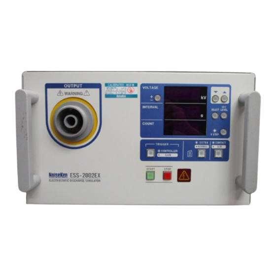
8. NAME AND FUNCTION OF EACH PART 8-1. Main Unit (Front Panel) Figure 8-1 Main Unit (Front Panel) [1] Model name The product name and model name of the instrument and the company logo. [2] High-voltage output connector Connector with a maximum output voltage of 30.5kV. The discharge gun connects to this connector. -
Page 19: Main Unit (Rear Panel)
8. NAME AND FUNCTION OF EACH PART 8-2. Main Unit (Rear Panel) [12] [11] [10] Figure 8-2 Main Unit (Rear Panel) [6] Warning text Indicates a warning, a risk of electric shock, that caution is required, and that you should refer to the instruction manual. -
Page 20: Discharge Gun
8. NAME AND FUNCTION OF EACH PART 8-3. Discharge Gun Please refer to the instruction manual for the discharge gun for more details. Waveform forming unit (cap unit) for IEC * Do not remove this part as it may affect the performance of the main unit. -
Page 21: Operation Panel
8. NAME AND FUNCTION OF EACH PART 8-4. Operation Panel [10] [11] Figure 8-4 Operation Panel [1] Output polarity selection switch Selects the polarity of the applied voltage. [2] ▼ ▲ up/down switches Adjusts the selected value up or down. If you hold down a switch, the value changes faster. - Page 22 8. NAME AND FUNCTION OF EACH PART [6] Static discharge mode selection switch Selects either contact discharge mode (CONTACT) [Switch LED turns on] or air discharge mode (AIR) [Switch LED turns off]. [7] Radiation level mode selection switch A special operation for selecting either normal mode (NORMAL) [Switch LED turns on] or extra mode (EXTRA) [Switch LED turns off] for the radiation from the discharge gun.
-
Page 23: Radiation Level Mode Function
9. RADIATION LEVEL MODE FUNCTION To improve the reliability of its electrostatic discharge simulators, Noise Laboratory released the new TC-815R discharge gun in 2004. The new discharge gun was an upgrade of the TC-815P model and featured reduced ringing in the output current waveform and lower radiated noise from the discharge gun. -
Page 24: How To Use The Radiation Level Modes
9. RADIATION LEVEL MODE FUNCTION [2] Different voltage waveform With IEC 61000-4-2 and ISO 10605 standards, there is the difference in the voltage waveform which does not have stipulation. Conditions under which differences in waveform appear. Electrostatic discharge mode: Contact discharge The electrostatic discharge is applied to a point at which the impedance between the discharge tip and discharge gun GND is 2MΩ... -
Page 25: How To Select Extra Mode (Extra)
9. RADIATION LEVEL MODE FUNCTION 9-4. How to Select Extra Mode (EXTRA) If the radiation level mode selection switch is held down when the POWER switch is turned on, the simulator starts up in extra mode (EXTRA). (When the POWER switch is turned on normally, the simulator starts in normal mode (NORMAL).) The radiation level mode selection cannot be changed while the simulator is running. -
Page 26: Connections
CONNECTIONS Turn the power switch to "Off" on the instrument before connecting or changing any of the cables Failure to comply with this rule may result in electric shock, injury, or misoperation. Do not insert objects into the instrument and its connectors Inserting metallic or flammable items into the ventilation slits, connectors, or other openings may result in fire, electric shock, or similar. -
Page 27: Connecting The Ac Power Cable
10. Connections 10-2. Connecting the AC Power Cable Plug the AC power cable into a socket that has a protective earth terminal The AC power cable provided with the instrument has a three-pin plug that connects to the power supply and protective earth terminal. The protective earth on the three-pin plug connects via the AC power cable to the metal parts on the instrument. -
Page 28: Operation
OPERATION 11-1. Turning the Power On or Off Press the "|" side of the power switch on the rear of the simulator to turn on the power. This lights up the operation panel display. Press the "O" side of the power switch to turn off the power and the operation panel display. - Page 29 11. OPERATION [2] VOLTAGE setting Press the SELECT switch until the VOLTAGE display starts blinking to indicate that the setting value can be changed. Use the ▼ and ▲ switches to increase or decrease the VOLTAGE setting. Pressing the ▼ down switch decreases the setting and pressing the ▲ up switch increases the setting.
-
Page 30: Interval Setting
11. OPERATION 11-2-2. INTERVAL Setting The INTERVAL setting specifies the repeat interval for the electrostatic discharge. The setting is displayed in the INTERVAL display. The setting range when the electrostatic discharge mode selection switch is set to contact discharge mode (CONTACT) [switch LED on] is 0.05s to 9.99s in 0.01s steps. However, the INTERVAL setting range is different depending on the radiation level mode selection switch setting, as shown in the table below. -
Page 31: Count Setting
11. OPERATION 11-2-3. COUNT Setting The COUNT setting specifies the number of electrostatic discharges. The setting is displayed on the COUNT display. The setting range is 1 to 999 in steps of 1. Continuous discharge can also be selected. Press the SELECT switch until the COUNT display starts blinking to indicate that the setting value can be changed. -
Page 32: Iec Level Selection Switch
11. OPERATION 11-2-4. IEC LEVEL Selection Switch The IEC LEVEL selection switch changes the VOLTAGE setting values to the voltages specified by the IEC61000-4-2 standard. The voltage setting is displayed on the VOLTAGE display. Electrostatic discharge mode Voltages specified in selection switch IEC61000-4-2 standard Contact discharge mode (CONTACT) - Page 33 11. OPERATION Note As the value displayed in the VOLTAGE display increments and decrements with the step size specified by the V STEP setting, set or enable the V STEP function after first setting the VOLTAGE. The up/down steps cannot exceed the VOLTAGE setting range (0.20 to 30.5kV). The full VOLTAGE setting range may not be available, depending on the V STEP setting.
-
Page 34: Contact/Air Setting
11. OPERATION 11-2-6. CONTACT/AIR Setting The CONTACT/AIR setting selects the electrostatic discharge mode. The available modes are contact discharge mode (CONTACT) and air discharge mode (AIR). Pressing the CONTACT/AIR switch toggles the setting between contact discharge mode (CONTACT) [switch LED on] and air discharge mode (AIR) [switch LED off]. CONTACT/AIR switch LED CONTACT/AIR setting Switch LED on... - Page 35 11. OPERATION Operation in CONTROLLER mode (main unit trigger mode) Pressing the START switch to start a test causes the TRIGGER switch on the simulator to start blinking indicating that it can be used to start and pause electrostatic discharging. In contact discharge mode (CONTACT), pressing the TRIGGER switch once starts electrostatic discharging in accordance with the specified settings.
-
Page 36: Starting And Stopping A Test
11. OPERATION 11-3. Starting and Stopping a Test 11-3-1. Starting a Test Warning ・ Before you start, check that the discharge gun is connected. ・ Starting a test will generate the indicated voltage. Take adequate precautions. ・ Take care to ensure there are no other people close to the discharge gun or simulator, and that all necessary preparation for the discharge test has been carried out. -
Page 37: Background Knowledge About Electrostatic Testing
BACKGROUND KNOWLEDGE ABOUT ELECTROSTATIC TESTING 1) Principle of electrostatic tester The basic circuit of an electrostatic is shown below. The high voltage generated in the high voltage power supply is charged in the charging capacitor through the charging relay and charging resistance. When the charging relay is turned off and the discharging relay is turned on, the high voltage (electric charge) accumulated in the charging capacitor is applied to EUT through the discharging resistance. - Page 38 12. Background Knowledge About Electrostatic Testing 3) Contact Discharge and Air Discharge The electrostatic discharge can be applied either by direct contact (CONTACT) or via the air (AIR). The test procedure and electrostatic simulator operation are different in each case, as described below. The effect on the EUT is also different. - Contact discharge (CONTACT) The electrostatic discharge is applied by placing the discharge tip in direct contact with the case of the EUT (if the case is painted, the paint is peeled off to...
-
Page 39: Error Display
ERROR DISPLAY Err 1 The discharge gun is not connected. Description of Interlock error error Press the STOP switch. How to clear error Insert the high-voltage input connector of the discharge gun into How to prevent the high-voltage output connector on the main unit of the error simulator. -
Page 40: Specifications
SPECIFICATIONS Simulator (ESS-2002EX) Parameter Function/Performance Output polarity Positive or negative 0.20kV to 30.0kV (30.5kVmax) 0.2kV to 1.0kV: 0.05kV step setting Output voltage 1.0kV to 30.0kV: 0.1kV step setting 0.20kV to 1.9kV ±10% Tolerance 2.0kV to 30.0kV ± 5% Normal mode (NORMAL): 0.05s to 9.99s ± 10% Repeat cycle Extra mode (EXTRA): 1.00s to 9.99s ±... -
Page 41: Warranty
WARRANTY Servicing terms The following terms are applicable to servicing by Noise Laboratory Co., Ltd., (hereafter referred to as the Company) provided to maintain the intended performance of its products. Scope The following terms shall apply only to products made by the Company. Technical servicing fee In the event of a failure of a product within the warranty period (see warranty section), the Company will repair a product without charge. - Page 42 15. Warranty Limited Warranty Noise Laboratory Co., Ltd. (hereafter referred to as the Company) warrants its products to be free from defects in materials and workmanship under normal use and service for a period of one year from date of delivery. In the event of failure of a product covered by this warranty, the Company will repair the product or may, at its option, replace it in lieu of repair without charge.
-
Page 43: Maintenance
MAINTENANCE When repair, maintenance or internal adjustment of the unit is required, a qualified service engineer takes charge of such work. Maintenance on the user side is restricted to the outside cleaning and functional check of the unit. When checking or replacing the fuse, turn off the switch of the unit and disconnect the plug socket beforehand. -
Page 44: Contacting Technical Support
CONTACTING TECHNICAL SUPPORT If you experience a malfunction, please have available both the model and serial number of your unit and contact the nearest distributor/agent or Noise Laboratory Technical Support. When it is necessary to send your unit back to Noise Laboratory, fill in the repair order form completely, pack the unit in the original package or equivalent one suitable for transit, and send the package. - Page 45 Memorandum...
- Page 46 Produced by: Noise Laboratory Co., Ltd. 1-4-4, Chiyoda, Chuo-ku, Sagamihara City, Kanagawa Pref., 252-0237, Japan TEL 042-712-2031 FAX 042-712-2030 Documents with missing or incorrectly bound pages will be replaced PRINTED IN JAPAN...
Need help?
Do you have a question about the ESS-2002EX and is the answer not in the manual?
Questions and answers