
Subscribe to Our Youtube Channel
Related Manuals for NoiseKen JSS-003


Summary of Contents for NoiseKen JSS-003
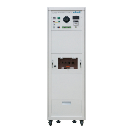
- Page 1 INSTRUCTION MANUAL AUTOMOTIVE TRANSIENT SURGE SIMULATOR MODEL JSS-003 NOISE LABORATORY CO., LTD. The 4.05 edition AEJ00006-00E-3F...
- Page 2 NOTICE • The contents of this instruction manual (the “Manual”) are subject to change without prior notice. • No part of the Manual may be reproduced or transferred, in any form and for any purpose, without the permission of Noise Laboratory Co., Ltd.(the “Company”) •...
-
Page 3: Important Safety Precautions
1. IMPORTANT SAFETY PRECAUTIONS Thoroughly understand the following precautions before use, as they are important matters for handling this unit in safety. 1. This unit cannot be used in an explosive area, fire prohibited area, etc. Use of this unit in such an area is liable to cause combustion or ignition. - Page 4 Memorandum...
-
Page 5: Application Form For Instruction Manual
2. APPLICATION FORM FOR INSTRUCTION MANUAL We place an order for an instruction manual. JSS-003 Model: Serial No.: Applicant: Company name: Address: Department: Person in charge: Tel No.: Fax No. this page "APPLICATION FORM INSTRUCTION MANUAL" from this volume and keep it for future use with care. - Page 6 Memorandum...
-
Page 7: Table Of Contents
3. TABLE OF CONTENTS 1. Important safety precautions ................1 2. Application form for instruction manual ............3 3. Table of contents .................... 5 4. Preface ......................6 5. Basic safety precautions for this simulator ............. 7 6. Name and function of each part ..............11 7. -
Page 8: Preface
This manual contains how to use the JSS-003 and other important information. In order to obtain the highest performance from your JSS-003, thoroughly understand the contents of this manual and use as ready reference for operation. This Instruction Manual will help operators handle and utilize the Automotive Transient Surge Simulator Model: JSS-003 in safety. -
Page 9: Basic Safety Precautions For This Simulator
5. BASIC SAFETY PRECAUTIONS FOR THIS SIMULATOR 5-1. Symbols of hazard It expresses a WARNING. WARNING 警告 WARNING indicates a potentially hazardous situation which, if not avoided, death or serious injury. could result in It expresses a CAUTION. CAUTION 注意 CAUTION indicates a potentially hazardous may result situation which, if not avoided,... - Page 10 【 Precautions for human body and connected to it may be damaged. connection】 12. To ensure safety operations, use the standard and optional accessories supplied by NOISEKEN. 13. When this unit is not used, remove the supplied switch key and keep in a safe place...
- Page 11 5. Safety basic precaution for this simulator CAUTION 注意 For the DC power supply, keep the maximum rating (refer to 9.Specifications.) Otherwise, the internal mechanism of this unit may be damaged. 【Precautions for operation】 15. Do not connect a DC input cable to SURGE OUT terminal directly, otherwise resulting in a damage to the inside of DC power supply and this simulator.
- Page 12 5. Safety basic precaution for this simulator CAUTION 注意 25. A caution label for power supply voltage is stuck above the AC input Use the unit within the range of ± ± ± ± terminal on the rear panel of this unit. 10% of power supply voltage.
-
Page 13: Name And Function Of Each Part
6. NAME AND FUNCTION OF EACH PART ① ② ⑲ ③ ⑱ ④ ⑰ ⑤ ⑥ ⑯ ⑦ !WARNING警告 ⑧ ⑨ ⑮ ⑭ ⑩ ⑬ ⑫ !WARNING警告 ⑳ ⑪ シリアルナンバー の位置 Serial number ① VOLTAGE ADJUST KNOB ⑬ DC IN TERMINAL ②... - Page 14 6. Name and function of each part ① ① ① ① VOLTAGE ADJUST KNOB (VOLT ADJ.) Switch to set to the peak value of the surge voltage. The set value is displayed on DIGITAL VOLTMETER⑲. ② ② ② ② HIGH VOLTAGE OFF SWITHCH When this switch is pressed, the lamp of HIGH VOLTAGE ON SWITCH③...
- Page 15 6. Name and function of each part ⑩ ⑩ ⑩ ⑩ DC BREAKER Breaker to protect the equipment being tested from short-circuiting on the load side. ⑪ ⑪ ⑪ ⑪ ACCESSORY BOX A drawer which accommodates accessories. ⑫ ⑫ ⑫ ⑫ DC G TERMINAL The minus (ground) side output terminal of the power supply to the equipment being tested is connected to this terminal.
-
Page 16: How To Connect Equipment
7. HOW TO CONNECT EQUIPMENT Thoroughly read Par. 5 “Fundamental Safety WARNING 警告 Precautions for Safety Performance” before doing connection and starting a test. 7-1 Preparation 1) Install the simulator on a level floor and put a stopper under the caster. When installing this unit, do not block the ventilating CAUTION 注意... -
Page 17: Connection With The Power Supply For Driving The Equipment Being Tested
7. Connection of the simulator 1) Connect the plus side power input terminal of the equipment being tested to the SURGE OUT TERMINAL ⑮ of the simulator. 2) Connect the minus side power input terminal of the equipment being tested to the SURGE G TERMINAL⑭... -
Page 18: Connection With A Power Supply For Driving The Simulator
7. Connection of the equipment SURGE OUT SURGE G DC IN DC G TERMINAL⑮ TERMINAL⑭ TERMINAL⑬ TERMINAL⑫ – – Power supply for driving Equipment to be tested the equipment to be tested (EUT) 7-4 Connection with a power supply for driving the simulator 1) Be sure that the POWER SWITCH⑦... -
Page 19: Operation
8. OPERATION Thoroughly read Par. 5 “Basic Safety Precautions for WARNING 警告 This Simulator” before doing connection and starting a test. 8-1. Power ON 1) Insert the supplied switch key into the POWER SWITCH⑦ and turn the switch key clockwise by 90 Thus, the power is supplied to the simulator and °. -
Page 20: Surge Voltage Setting
(transient voltage) in the no-load state. The maximum transient voltage Vp specified in JASO Standard and the maximum set voltage of the JSS-003 are as shown in Table 1 below : Class of test Set Voltage (V) Maximum set voltage Vp (V) of JSS-003 100 ±10%... -
Page 21: How To Set The Counter
8. Operation Procedure 8-5. How to set the counter Display unit (number of times) Count up indicating LED RESET RESET SWITCH Preset counter COUNTS * Never turn this knob as it has been TIME preadjusted before delivery. Set the number of times of surge application previously with the SURGE APPLICATION SET COUNTER⑱... -
Page 22: Execution Of Test
8. Operation Procedure 8-6. Execution of test After completion of the above-mentioned settings, start the test. Be careful of generated surge and an electric shock which WARNING 警告 【Precautions for may occur in the power supply to EUT. human body and operation】 1) Be sure that the DC BREAKER⑩... -
Page 23: Specifications
9. SPECIFICATIONS 9-1. Surge generating unit The waveform and constant of each class of surge conforms to JASO D001-94. Surge output voltage Attenuation Parallel Output DC cut constant(τ) (Vp) resistor impedance time (ts) 100V±10% 2Ω 0.8Ω Class 200ms ±10% ±10% ±10% maximum Infinitely variable... -
Page 24: Main Control Unit
9. Specifications 9-2. Main control unit Item Specifications 30s ±10% Repetition cycle of surge generation Surge output voltage display 3-digit 7-segment 1 ~ 999999 Repetition frequency of surge generation ( Can be set by 6-digit preset counter) Surge output channel 1 channel Power capacity of equipment 50V DC 10A maximum... -
Page 25: Standard Accessories
10. STANDARD ACCESSORIES Quantity A : Power cable B : Switch key C : Fuse(10A) D : Instruction manual E : Accessory bag... -
Page 26: Waveform Check/Observation
11. WAVEFORM CHECK/OBSERVATION Each surge waveform can be observed by connecting an oscilloscope to the output terminals ( between SURGE OUT TERMINAL⑮and SURGE G TERMINAL⑭) of this unit . 11-1. Voltage waveform of class A and class D surges : Maximum value of transient 重畳しない時... -
Page 27: Block Diagram
BLOCK DIAGRAM A-1 A-2 B-1 AC IN MC B-2 SURGE OUT D-1 GND D-2 E DC IN : Main control unit : Class A-1 Surge generation unit : Class A-2 Surge generation unit : Class B-1 Surge generation unit : Class B-2 Surge generation unit : Class D-1 Surge generation unit : Class D-2 Surge generation unit : Class E Surge generation unit... -
Page 28: Warranty
13. WARRANTY 10.1 Servicing terms The following terms are applicable to servicing by Noise Laboratory Co., Ltd., (hereafter referred to as the Company) provided to maintain the intended performance of its products. 1. Scope The following terms shall apply only to products made by the Company. 2. - Page 29 10.2 Limited warranty Noise Laboratory Co., Ltd. (hereafter referred to as the Company) warrants its products to be free from defects in materials and workmanship under normal use and service for a period of one year from date of delivery. In the event of failure of a product covered by this warranty, the Company will repair the product or may, at its option, replace it in lieu of repair without charge.
-
Page 30: Maintenance
14. Maintenance When repair, maintenance or internal adjustment of the unit is required, a qualified service engineer takes charge of such work. Maintenance on the user side is restricted to the outside cleaning and functional check of the unit. When checking or replacing the fuse, turn off the switch of the unit and disconnect the plug socket beforehand. -
Page 31: Noise Laboratory Support Network
NOISE LABORATORY SUPPORT NETWORK If a symptom which seems a trouble is found, inform the model name and serial number of the product together with the symptom to Noise Laboratory or your nearest sales agent of Noise Laboratory. When the product is returned to Noise Laboratory, write the state of the trouble, contents of your request, model name and serial number in a repair order, and pack the product and repair order sheet in the former package of equivalent suitable for transit and send them back. - Page 32 NOISE LABORATORY CO., LTD. 1-4-4, Chiyoda, Chuo-ku, Sagamihara City, Kanagawa Pref., 252-0237, Japan TEL: +81-(0)42-712-2051 FAX: +81-(0)42-712-2050 URL: http://www.noiseken.co.jp Printed in Japan...
Need help?
Do you have a question about the JSS-003 and is the answer not in the manual?
Questions and answers