
Related Manuals for NoiseKen IJ-4050


Summary of Contents for NoiseKen IJ-4050
- Page 1 INSTRUCTION MANUAL AC LINE CDN for Impulse Noise Simulator IJ-4050 MODEL NOI SE LAB ORAT ORY CO . , LTD . Edition 1.09 AEB00105-00E-0...
- Page 3 NOTICE The contents of this booklet are subject to change without prior notice. No part of this booklet may be reproduced or transferred, in any form, for any purpose, without the permission of Noise Laboratory Co., Ltd. The contents of this booklet have been thoroughly checked. However, if a doubtful point, an error in writing or a missing is found, please contact us.
-
Page 5: Important Safety Precautions
1 IMPORTANT SAFETY PRECAUTIONS The following is very important matters in order to safely handle this product (called unit hereafter). Read carefully them and strictly observe them. Use of this unit in an explosive area such as "No fire" area etc. is prohibited. - Page 6 P r e f a c e Thank you very much for your purchasing our AC LINE CDN unit for Impulse Noise Simulator Model: IJ-4050. In order to obtain the highest performance from this unit, it is recommended that the contents of this manual be thoroughly...
-
Page 7: Application Form For Instruction Manual
2 APPLICATION FORM FOR INSTRUCTION MANUAL We place an order for an instruction manual. Model: IJ-4050 Serial No.: Applicant: Company name: Address: Department: Person in charge: Tel No.: Fax No.: line Cut off this page "application form for instruction manual" from this volume and keep it for future use with care. - Page 8 Memo...
-
Page 9: Basic Safety Precautions
3 BASIC SAFETY PRECAUTIONS WARNING SIGNS AND THEIR MEANINGS a warning. Means If such a danger is not avoided, a potential danger which may result in a death or serious injury will be caused. a caution. Means If such a danger is not avoided, a potential danger which may result in a minor or medium degree of injury will be caused. - Page 10 When conducting coupling tests to the EUT LINE, the signal ground of the HV pulse generator circuit and one line (phase) of the EUT LINE may be connected, causing a shock hazard if the users touch the outer conductor of the HV coaxial connectors. In addition, if the outer conductor of the HV coaxial connectors is connected to any grounded subject, leak current will flow, tripping the ground fault interrupter embedded in the facilities.
- Page 11 The SG terminal provided on the front panel of this unit functions as the signal reference ground for testing. The PE terminal (EUT) is for the protective earth conductor for the EUT. The protective earth terminals for this unit itself are the AC inlet earth pin (AC INPUT) and PE positioned in close proximity.
-
Page 12: When Warning Label Is Missing
Using solvents may spoil the appearance. [Precautions for handling] The coaxial connectors used for this unit is of NoiseKen original design. Use of other type of connectors may cause electric shock hazards or malfunctions of the unit. -
Page 13: Table Of Contents
EST SET UP ....26 9.4.1 Line to ground mode (common mode) for AC operated equipment ......27 9.4.2 Line to line mode (normal mode) for AC operated equipment SPECIFICATIONS ..................28 WARRANTY ....................29 MAINTENANCE....................31 NOISEKEN SUPPORT NETWORK ..............32... -
Page 14: General Description
5 GENERAL DESCRIPTION This unit can be used for AC LINE INJECTION TEST up to AC415V 50A 3-phase 5-wire (L1, L2, L3, N, PE). Easily selectable coupling modes (Normal mode, Common mode) by supplied SG short plug. Operation in synchronization with the relevant supply available in case of use with INS-4001, INS-4020/4040. -
Page 15: Included Accessories
6 INCLUDED ACCESSORIES This product includes the following accessories. D ACCESSRIES ITEM NOTE Line Sync BNC cable 40cm length Injection coaxial cable 40cm length SG short plug (02-00106A) Line input cable 4pcs 2m length φ 6 terminal PE cable 2m length φ 6 terminal Line output cable 5pcs 0.2m length φ... -
Page 16: Apperance And Functions
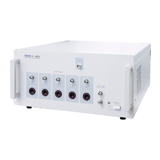
7 APPERANCE AND FUNCTIONS Front panel Front view 1. POWER switch controls mains POWER on and off. When pressed, the button is locked in the down position with turning on the LED. 2. SG connector HV pulse signal ground connector When conducting common mode coupling test with reference to a ground plane, this connector shall be plugged with the supplied short plug. - Page 17 4. SYNC OUT terminal Outputs zero cross signals of L1-L2 for EUT AC LINE synchronization test. Connect the supplied Line Sync BNC cable to the EXT TRIG terminal of the INS-4001, and press the LINE PHASE mode button. This output circuit is an open-collector and can drive up to 24V/5mA signal. L1-L2 LINE SYNC OUT 10Ω...
-
Page 18: Rear Panel
Rear panel Rear view a. AC INPUT AC mains input to operate this unit. On 100V to 115V operation, the supplied AC cord can be used for connection to an appropriately grounded AC supply. (The unit operates on a range of 100V to 240V AC. In case of 200-240V operation, user shall use an appropriate AC cord that conforms to the power capacity and the relevant safety standard.) b. - Page 19 When the lever is pulled to the upper position, the EUT LINE turns on. In case of over current, this breaker will trip, turning off the EUT LINE. Check the cause of the over current event. After removing it, pull up the lever again.
-
Page 20: Connection And Operation
8 CONNECTION AND OPERATION Observe operating precautions when conducting a test by using this simulator. The following figure shows the set up of this unit with INS-4001. The set up with INS-4020 / 4040 is similar to the figure as below. Set up Place this unit under the impulse noise simulator. -
Page 21: Connection Of Sg
a. Loosen screws sufficiently (L1, L2, L3, N, PE) on the EUT LINE INPUT terminal by rotating them counterclockwise. b. Insert the cable into the holes on the front of the terminal. c. Tighten the screws to fix the cable with bigger torque (about 2.0-2.3 Nm) than usual. -
Page 22: Connection Of Sync Out
Connection of SYNC OUT When testing the EUT in AC line synchronization mode, connect this terminal to EXT TRIG terminal of the INS-4001 unit with the supplied Line Sync BNC cable. Set the INS-4001 in the LINE PHASE mode to test the EUT for its AC line synchronized pulses. -
Page 23: Connection With Ins-410/420 Series
T-type branch connector. ③ Connect from the output of 50Ω terminator to a injection terminal of IJ-4050 with a conversion cable Model: 02-00003A (Option). ④ EUT LINE INPUT shall be power-fed from an isolation transformer. Please refer to Section 9 Test set up. -
Page 24: Connection With Ins-4310/4320 Se Ries
T-type branch connector. ③ Connect from the output of 50Ω terminator to a injection terminal of IJ-4050 with the supplied Injection coaxial cable. ④ EUT LINE INPUT shall be power-fed from an isolation transformer. Please refer to Section 9 Test set up. -
Page 25: Connection With Ins-400L
8.11 Connection with INS-4410/4420 series When connecting with INS-4410/4420 series, connect from the R termination out of the simulator to an injection terminal of IJ-4050, in the same manner as INS-410/420/4310/4320, with a conversion cable Model: 02-00002A (option). -
Page 26: Connection With Ins-Ax Series
TERMINATION POWER TRANSFORMER R(left) EXT. CLOCK S(right) INJECTION POWER INPUT INPUT IJ-4050 EUT LINE EUT LINE ISOLATION OUTPUT INPUT TRANSFORMER POWER ① Connect the PULSE OUT of the INS-AX to the built-in 50 Ω termninator of the IJ-02/IJ-03. ② Connect from the 50Ω termination out to a injection terminal of... -
Page 27: Connection With Ins-Ax2 Series
INPUT POWER TRANSFORMER ① Connect the PULSE OUT of the INS-AX2 to INJECTION INPUT of IJ-4050 of the line to be injected.with the attached coaxial cable. ② EUT LINE INPUT shall be power-fed from an isolation transformer. Please refer to Section 9 Test set up. - Page 28 ③ For EUT line synchronization test, select PHASE (LINE SYNCHRONIZED) mode for INS-AX2 simulator. INS-AX2 series simulators have function to generate impulses synchronized with input signal to EUT LINE INPUT on rear panel of the unit. With L1, L2 of EUT POWER connecting to EUT LINE INPUT of INS-AX2, turn on LINE ON switch, select PHASE injection mode, and conduct test.
-
Page 29: Test Set Up
A recommended test set-up example is shown here. It consists of the following: Wooden test table (for table-top equipment) Ground plane and ground cable Power supply for the simulator Power supply for the EUT and an isolation transformer (AC powered testing) GROUND PLANE ISOLATION TRANSFORMER IJ-4050... -
Page 30: Test Set Up
Test set up 9.4.1 Line to ground mode (common mode) for AC operated equipment INS-4001, INS-4020/4040 PULSE OUT 50ΩTERM IN 50ΩTERM OUT IJ-4050 EUT LINE INPUT EUT OUTPUT EUT L1 EUT L1 EUT L2 EUT L2 EUT L3 EUT L3... -
Page 31: Line To Line Mode (Normal Mode) For Ac Operated Equipment
9.4.2 Line to line mode (normal mode) for AC operated equipment INS-4001, INS-4020/4040 PULSE OUT 50ΩTERM IN 50ΩTERM OUT IJ-4050 EUT LINE INPUT EUT OUTPUT EUT L1 EUT L1 EUT L2 EUT L2 EUT L3 EUT L3 AC IN EUT N... -
Page 32: Specifications
10 SPECIFICATIONS ■ SPECIFICATIONS Parameters Specifications Notes Maximum input voltage 8kV max without 50Ω termination 4kV with 50Ω termination EUT power capacity 3-phase 5-wire (L1, L2, L3, N, PE) Do not use for DC power. AC415V 50A L1-L2,L2-L3,L3-L1:AC415V L1,L2,L3-N:AC240V Coupling mode selection By short plug connection L1, L2, L3, N, PE Coupling mode Normal/Common... -
Page 33: Warranty
11 WARRANTY The following terms are applicable to servicing by Noise Laboratory Co., Ltd., (hereafter referred to as the Company) provided to maintain the intended performance of its products. 1. Scope The following terms shall apply only to products made by the Company. 2. - Page 34 Limited warranty Noise Laboratory Co., Ltd. (hereafter referred to as the Company) warrants its products to be free from defects in materials and workmanship under normal use and service for a period of one year from date of delivery. In the event of failure of a product covered by this warranty, the Company will repair the product or may, at its option, replace it in lieu of repair without charge.
-
Page 35: Maintenance
12 MAINTENANCE The mercury relay is an expendable supplies. If a symptom such as output pulse unstable, etc happens, the mercury relay shall be replaced. When repair, maintenance or internal adjustment of the unit is required, a qualified service engineer takes charge of such work. Maintenance on the user side is restricted to the outside cleaning and functional check of the unit. -
Page 36: Noiseken Support Network
13 NOISEKEN SUPPORT NETWORK If a symptom that seems a trouble is found, check the symptom against the following check sheet and inform the model name and serial Number of the product together with the symptom to Noise Laboratory or our nearest sales agent in your area. - Page 38 NOISE LABORATORY CO., LTD. 1-4-4, Chiyoda, Chuo-ku, Sagamihara City, Kanagawa Pref., 252-0237, Japan TEL: +81-(0)42-712-2051 FAX: +81-(0)42-712-2050 URL: http://www.noiseken.co.jp Printed in Japan...
Need help?
Do you have a question about the IJ-4050 and is the answer not in the manual?
Questions and answers