
Subscribe to Our Youtube Channel
Related Manuals for NoiseKen ISS-7610


Summary of Contents for NoiseKen ISS-7610
- Page 1 INSTRUCTION MANUAL AUTOMOTIVE TRANSIENT SURGE SIMURATOR ISS-7610 MODEL Noise Laboratory Co., Ltd. E d i t i o n AEJ00367-00E-1-E...
- Page 2 NOTICE • The contents of this instruction manual(the “Manual”)are subject to change without prior notice. • No part of the Manual may be reproduced or transferred, in any form and for any purpose, without the permission of Noise Laboratory Co., Ltd.(the “Company”).
-
Page 3: Important Safety Precautions
1. IMPORTANT SAFETY PRECAUTIONS The following instructions are very important for safe handling of ISS7610 (the “Unit”). Read them carefully before use. 1. Do not use the Unit near flammable materials or fire sources. When used, there is a risk of fire due to pulses, etc. 2. - Page 4 Memorandum - 2 -...
-
Page 5: Application Form For Instruction Manual
2. APPLICATION FORM FOR INSTRUCTION MANUAL We place an order for an instruction manual. Model: ISS-7610 Serial No.: Applicant: Company name: Address: Department: Person in charge: Tel No.: Fax No. Cut off this page “APPLICATION FORM FOR INSTRUCTION MANUAL” from this volume and keep it for future use with care. - Page 6 Memorandum - 4 -...
-
Page 7: Table Of Contents
3. CONTENTS 1. IMPORTANT SAFETY PRECAUTIONS ..............1 2. APPLICATION FORM FOR INSTRUCTION MANUAL ........... 3 3. CONTENTS ......................5 4. PREFACE ....................... 6 5. BASIC SAFETY PRECAUTIONS ................7 5-1. S ................7 YMBOLS OF AZARD 5-2. B ..............7 ASIC AFETY RECAUTIONS... -
Page 8: Preface
Unit through the software, please read the instruction manual of Remote Control Software thoroughly in addition to the Manual to ensure safety and correct procedures. The Manual will let you operate ISS-7610 safely and make the most use of it if you strictly follow the operational procedures and the safety instructions. -
Page 9: Basic Safety Precautions
5. BASIC SAFETY PRECAUTIONS 5-1. Symbols of Hazard Indication of Warning The following warning indication is placed on the upper left of the rear-panel of the Unit, and alerts a risk of electric shock. This sign indicates the presence of “dangerous voltage/current” that may endanger persons. - Page 10 When changing fuses, choose the same melt off type and rating. Also, be sure to unplug the AC chord before changing fuses. 【 【 【 【 P recautions regarding use and safety 】 】 】 】 Do not supply the Unit with voltage or overload beyond the specification range.
-
Page 11: Loss Of Warning Label
14. Do not wipe the body of the Unit with solvents such as lacquer thinner or alcohol. When the Unit gets dirty, wipe it with a detergent moistened fabric etc. 【 【 【 【 P recautions regarding use 】 】 】 】 15. -
Page 12: Main Features
Interface Unit and Remote Control Software for the purpose of communication between the Unit (ISS-7610) and the PC. (When used standalone without mounting to a rack) An optional ISS-7690 is capable of integrated pulse output when the Unit is installed onto System Rack ISS-7602 (Optional). -
Page 13: Schematic Circuit Diagram Of The Unit
6-2. Schematic Circuit Diagram of the Unit The injection methods of Pulse 1 and Pulse 2a to DC are different, and the Unit generated the Pulse 1 and Pulse 2a by switching within the internal circuit. DC input for both Pulse 1 and 2a is controlled by DC LINE switch. -
Page 14: Regarding Iso7637-2 (Second Edition 2004-06-15)
The path taken by the Pulse 2a current in the Unit is shown in Fig. 3. First, the electric charge stored in C1 flows through the circuit as the pulse current. Next, pulse current from HOT terminal flows through DUT to GND. The current goes to negative (-) DC INPUT terminal, and flows back to C1 after flowing through the power source, etc. - Page 15 a ) P u l s e a d j u s t m e n t Fig. 4 Test Configuration (For Pulse Veification) When verifying the Unit waveform, do not connect DUT with the output open-circuited. Turn the DC LINE ON (also set the circuit breaker ON), while positive (+) and negative (-) terminals of DC INPUT are short-circuited.
- Page 16 Pulse 1 Waveform Standard (ISO7637-2 (Second edition 2004-06-15)) 0.1Us 0.9Us Fig. 5 Pulse 1 Waveform Table 1 Pulse 1 Parameters Parameter 12V System 24V System -75V ~ -100V -450V ~ -600V 10 Ω 50 Ω Output 1 (+0, -0.5) μ s 3 (+0, -1.5) μ...
- Page 17 Pulse 2a Waveform Standard 0.9Us 0.1Us Fig. 6 Pulse 2a Waveform Table 3 Pulse 2a Parameters Parameter 12V System 24V System +37V ~ +50V 2 Ω Output 0.05ms Open 1 (+0, -0.5) μ s 0.2s ~ 5s Table 4 Pulse 2a Annex D Parameters Test Pulse 2a No Load 50V ±...
-
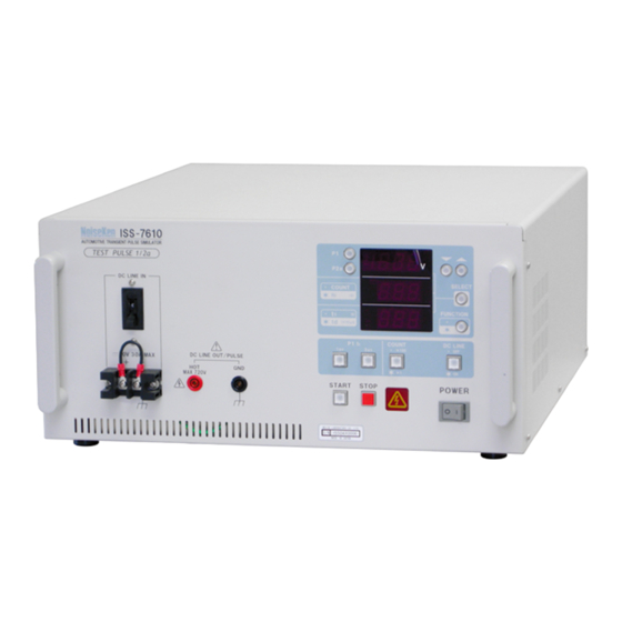
Page 18: Part Names And Functions
7. PART NAMES AND FUNCTIONS Main Unit (ISS-7610) ① Control Panel Circuit Breaker ④ Output Terminal GND ⑥ ⑤ Output Terminal HOT ② Power Switch ③ DC Input Terminals Fig. 7 Front Panel ⑨ AC Source Voltage Selection Terminals Communication Terminals Interlock Terminal ⑩... - Page 19 ① Control Panel The control panel located on the front of the Unit lets you set local settings. Pulse Selection Buttons UP / DOWN Button Us Display SELECT Button COUNT / Ri Display FUNCTION Button t1 / td Display DC LINE Button tr Configuration Button COUNT Multiplier Button...
- Page 20 D t1 / td Display The “t1 / td Display “ displays either t1 or td value. t1 will be displayed when FUNCTION is not lit, and td when lit. When the START button is pressed, the display will automatically change to t1 (FUNCTION will become unlit), and the remaining time to pulse output will decrease 0.1 second by 0.1 second.
- Page 21 tr Configuration Switch The “tr Configuration Switch” is only functional for Pulse 1, and sets the rise time. Light the 1 s button when performing 12V tests, and 3 s button when performing 24V tests. µ µ Both buttons will be unlit for Pulse 2a. K START Button By pressing the “START Button”...
- Page 22 Circuit Breaker ④ The “Circuit Breaker” serves as protection against DUT short circuits. It is inserted between the “+” of DC Input Terminal ③ and the Output Terminal (HOT) ⑤ . Raise the lever for electrical continuity. It goes down (or trips) when an over current is detected. It trips when the current exceeds 40A .
- Page 23 ⑩ Communication Terminal By connecting the Unit to a PC using the optional parts Optical Interface Unit and Remote Control Software through this “Communication Terminal”, parameter settings, START, and STOP can be controlled from the PC. Refer to section “9. Remote Controlling by PC” for connection procedures.
- Page 24 ⑫ Ventilation Fan The “Ventilation Fan” is for cooling the internal devices. Do not block the vents. ⑬ External Output Terminals The “External Output Terminals” are for outputting P3a/P3b pulses from ISS-7690 (CDN). Do not connect anything to these ports when using standalone. There is a risk of electric shock.
-
Page 25: Test Procedure
8. TEST PROCEDURE 8-1. Pre-Operation Check Check the installation environment, wiring, and terminal connections. ・ Confirming the Installation Location Read the “Important Safety Instructions” and set the Unit in accordance with the ISO Standards or the test plan. ・ Inserting Interlock Plug Connect the accessory Interlock Plug onto “... -
Page 26: Setting Parameters
8-2. Setting Parameters The previous settings except DC LINE ON/OFF are preserved immediately after the Power Switch is turned ON. The displays are also the same as the settings immediately before turning OFF. ・ Selecting Pulse 1 / 2a Use “A Pulse Selection Button” to select the Pulse to be used in the test. ・... -
Page 27: Starting And Finishing Test
8-3. Starting and Finishing Test Be sure to carry out “11 Pre-Start Checkup (Waveform Verification)” prior to proceeding with a test Start the test after completing the checkups and various settings. ・ Start Keep pressing the START Button for 1 second or more. A beep sounds, “Warning Lamp M”... -
Page 28: Fan Stop Error
8-4. FAN Stop Error In addition to “ ⑫ Ventilation Fan ” , the Unit has fans for internal ventilation. When these internal fans stop for any reason, the LED will display E rr as shown in Fig.13. When this “... -
Page 29: Remote Control By Pc
9. REMOTE CONTROL BY PC 9-1. Preparation ・ The Remote Control Software on a PC (Personal Computer) lets you control the Unit externally. FG, SG, and PE of the Unit and the FG of the PC can be isolated. Once communication with the Remote Control Software is established, you cannot control the Unit locally any more. -
Page 30: Installing The Software
9-3. Installing the Software Install the “Remote Control Software”ISS-7601 onto PC using the DISK of the Remote Control Software. Refer to the instruction manual of Remote Control Software for installation procedure (shown in Figure 15). Fig. 15 Installing Software 9-4. Installing Remote Control Software Refer to the instruction manual of Remote Control Software for installation procedure. -
Page 31: Product Specifications
10. PRODUCT SPECIFICATIONS Table6 Product Specifications - Common Parameters Specification Parameter Test Pulse 1 Test Pulse 2a ISO 7637-2(Third edition 2011-03-01) ISO 7637-2(Second edition 2004-06-15) Corresponding Standards ISO/DIS 7637-2.3(2003-05-20) ISO/DIS 7637-2.2(2002-07-16) -5V ~ -720V ± 10% 5V ~ 3 00V ± 1 0% 1V intervals intervals (... - Page 32 Table 7 Tolerance specified by Annex D Test Pulse 1 Load No Load -100V ± 1 0V 1 (+0, -0.5) 2000 ± 4 00 µ µ µ 12V System Load -50V 1 0V Ω ± - 1500 3 00 ± µ...
-
Page 33: Waveform Verification
11. WAVEFORM VERIFICATION Before starting the test, verify that the Unit is outputting the pulse normally. The verification is made in accordance with Annex D of ISO Standards. Waveform Verification Procedure 1. Be sure to short circuit the + and of the D C Input Terminals with the accessory... -
Page 34: Accessories
12. ACCESSORIES Short Lead Cable Replacement FUSE Instruction Manual Interlock Plug (For waveform check) 3.15A Output Cable 2m AC Cable DC Input Cable 2m (one red, one black) - 32 -... -
Page 35: Options
13. OPTIONS N o i s e K e n Remote Control Software Optical Interface Unit ISS-7601 07-00022A Waveform Verification Load (2 Waveform Verification Load (10 Waveform Verification Load (50 Ω Ω Ω 06-00061A 06-00062A 06-00063A - 33 -... -
Page 36: Warranty
14. WARRANTY Services The following terms are applicable to the services provided by the Company to maintain and repair the Unit. Scope The Unit and accessories and options provided by the Company are covered under this section. Technical Service Fee Any repairs provided by the Company during the warranty period will be free of charge in accordance with the Limited Warranty. - Page 37 Limited Warranty In the event of failure during the warranty period, the Unit will be repaired or replaced free of charge. Decision of the repair method shall be left at the discretion of the Company. This limited warranty is applicable in Japan only. Scope This warranty is applicable only to the Unit and its accessories.
-
Page 38: Maintenance
15. MAINTENANCE Should the necessity of services such as repair, maintenance, or internal calibration arise, leave them to qualified service personnel only. Limit your own maintenance works to exterior surface cleaning and functional tests. When checking or changing replaceable fuses, turn OFF the power switches of the Unit and connected devices (if any). -
Page 39: Noise Laboratory Support Network
16. NOISE LABORATORY SUPPORT NETWORK If a symptom which seems a trouble is found, inform the model name and serial number of the product together with the symptom to Noise Laboratory or your nearest sales agent of Noise Laboratory. When the product is returned to Noise Laboratory, write the state of the trouble, contents of your request, model name and serial number in a repair order, and pack the product and repair order sheet in the former package of equivalent suitable for transit and send them back. - Page 40 NOISE LABORATORY CO., LTD. 1-4-4, Chiyoda, Chuo-ku, Sagamihara City, Kanagawa Pref., 252-0237, Japan TEL: +81-(0)42-712-2051 FAX: +81-(0)42-712-2050 URL: http://www.noiseken.co.jp Printed in Japan...
Need help?
Do you have a question about the ISS-7610 and is the answer not in the manual?
Questions and answers