
Subscribe to Our Youtube Channel
Related Manuals for NoiseKen LSS-6330-A20


Summary of Contents for NoiseKen LSS-6330-A20
- Page 1 INSTRUCTION MANUAL LIGHTNING SURGE SIMULATOR LSS-6330-A20 MODEL NOISE LABORATORY CO., LTD. The 1.02 edition AEE00663-00E-0...
- Page 2 NOTICE The contents of this instruction manual (the “Manual”) are subject to change without prior notice. No part of the Manual may be reproduced or distributed, in any form or by any means, without the authorization of Noise Laboratory Co., Ltd. (the “Company”). ...
-
Page 3: Important Safety Precautions
The following instructions are very important for safe handling of the lightening surge simulator LSS-6330-A20 (hereinafter “the Unit”). They must be kept strictly to prevent users of the Unit from receiving harm or damage through using the Unit. Read them carefully before use. -
Page 4: Check Package Contents
2. CHECK PACKAGE CONTENTS Before using the instrument, check whether the included accessories are complete according to the following list. A:AC cable ------------------------------------------------------------------------------------------ 1 B:Line output cable -------------------------------------------------------------------------------- 3 C:FG cable (2m) (MODEL:05-00070A M6-M6) ---------------------------------- 1 D:Coaxial cable for monitoring (1m) (MODEL:02-00128A BNC-BNC) ------ 1 E:Interlock connector ----------------------------------------------------------------------------- 1 F:Surge output confirmation cable set (Plug-round crimp terminal cable 0.5m x 2, plug-plug cable 1m x 1) --------------------- 1 set... -
Page 5: Application Form For Instruction Manual
3. APPLICATION FORM FOR INSTRUCTION MANUAL We place an order for an instruction manual. Model: LSS-6330-A20 Serial No.: Applicant: Company name: Address: Department: Person in charge: Tel No.: Fax No. Cut off this page “APPLICATION FORM FOR INSTRUCTION MANUAL” from this volume and keep it for future use with care. - Page 6 MEMO...
-
Page 7: Preface
4. PREFACE We thank you very much for your purchase of our Lightening Surge Simulator LSS-6330-A20 (hereinafter “the Unit”). This instruction manual (“the Manual”) contains how to use the Unit and other important information. In order to obtain the highest performance from the Unit, thoroughly understand the contents of the Manual and use as ready reference for operation. -
Page 8: Table Of Contents
5. CONTENTS 1. IMPORTANT SAFETY PRECAUTIONS ....................1 2. CHECK PACKAGE CONTENTS ......................2 3. APPLICATION FORM FOR INSTRUCTION MANUAL ..............3 4. PREFACE ..............................5 4-1.Feature ···························································································································································································· 5 5. CONTENTS ..............................6 6. BASIC SAFETY PRECAUTIONS......................9 6-1.Symbols of Hazard ······································································································································································· 9 6-2.Symbols of Instruction, Warning and Caution ·····················································································································... - Page 9 CONTENTS Connection of AC/DC Line Input ............................26 Connection of AC/DC Line Output............................27 11. OPERATION ............................. 28 11-1.Power ON unit·········································································································································································· 28 11-2.Emergency Stop Button························································································································································ 28 How to cancel emergency stop ............................... 28 11-3.Main Menu ················································································································································································· 29 11-4.Screen Flowchart ···································································································································································· 30 11-5.Inputting Numbers and Letters (About Ten Key and Character Key) ···································································...
- Page 10 CONTENTS EUT LINE Voltage Detection ..............................59 External Trigger .................................... 60 Interlock Level ....................................61 Sequence Method ..................................61 Title Operation ....................................61 Phase Angle Correction ................................61 EUT FAIL Signal ................................... 62 PHASE ANGLE CORRECTION ....................63 17. PRE CHECK ............................. 65 ERROR MESSAGE ........................
-
Page 11: Basic Safety Precautions
6. BASIC SAFETY PRECAUTIONS The following items are very important instructions which users must follow to take precautions against possible injury and harm. The indications are provided as an explanation of potential danger involved if the safety precautions are not observed correctly. 6-1. - Page 12 BASIC SAFETY PRECAUTIONS Noticing possibility of an electric shock It indicates that there is possibility of an electric shock. Noticing caution, warning and danger It indicates that there is a possibility of harm or physical damage if the Unit is or related equipment is handled incorrectly and that the Manual should be referred.
-
Page 13: 6-3.Danger
BASIC SAFETY PRECAUTIONS 6-3. Danger Do not take the Unit apart or remodel. Do not open the cover. Imminent danger might occur resulting in death or serious injury. Repair, internal adjustment, and inspection of the Unit should be performed by a qualified service Do not engineer. - Page 14 BASIC SAFETY PRECAUTIONS Watch equipment while the Unit is operating. If this instruction should not be followed, a third person or equipment related to the test may be exposed to a danger. Supply power within the indicated range (AC100 V~240 V). The misuse may cause an electric shock or a fire.
-
Page 15: 6-5.Caution
BASIC SAFETY PRECAUTIONS Do not damage AC cord. A damaged AC cord may cause a fire or an electric shock. For HV cable, be sure to take notice following points. Do not work it. Do not bend it forcibly. ... - Page 16 BASIC SAFETY PRECAUTIONS Do not work alone when moving the installation. This unit is heavy. When moving the installation site, take safety measures by multiple people. Do not install the Unit on following places. Setting up the Unit on wrong places as follows may result in a fire, an electric shock, or an injury.
-
Page 17: Caution About Expendable Supplies
7. CAUTION ABOUT EXPENDABLE SUPPLIES About a high voltage relay inside A high voltage relay used inside is an expendable component. The lifetime of it is dependent on using conditions and environment. If a symptom which seems to be caused by an exhausted high voltage relay, e.g. unstable current value, unstable repetition cycle or so on, is found, contact Noise Laboratory or your closest sales agent of Noise Laboratory. -
Page 18: Introductory Notes
8. INTRODUCTORY NOTES 8-1. Introductory Notes The meaning of following symbols is as follows. Operate the touch panel. Additional explanation. Indicating other parts to be referred in the Manual. Indicating restriction of setting up. Indicating items to be confirmed before usage. 【... -
Page 19: 8-3.Definition Of Surge Waveform
INTRODUCTORY NOTES 8-3. Definition of Surge Waveform Voltage Surge Waveform Fig 8-1 Voltage surge waveform Front time (T1): 1.67 times of the interval of time between the instants when the voltage value increases to 30% and 90% of the peak value. Duration (T2): Time interval between the instant at which the surge voltage rises to 0.5 of its peak value, and then falls to 0.5 of its peak value Fig 8-2 RINGWAVE Voltage waveform... -
Page 20: 8-4.Block Diagram
INTRODUCTORY NOTES 8-4. Block Diagram... -
Page 21: Appearance And Function Of Each Part
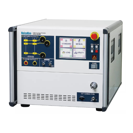
9. APPEARANCE AND FUNCTION OF EACH PART 9-1. Appearance of The Main Unit Rear Panel Front Panel... -
Page 22: 9-2.Front Panel
APPEARANCE AND FUNCTION OF EACH PART 9-2. Front Panel Emergency stop button 【EMERGENCY】 Stop button for emergency. Avoid using this button for ordinary stop. START switch 【START】 Used to start a test. Starting is available when a lamp of switch is blinking. Pressing key while conducting test makes the output pausing. - Page 23 APPEARANCE AND FUNCTION OF EACH PART EUT line output terminals 【EUT LINE OUTPUT】 EUT line output terminal of L/N/PE. The EUT shall be connected to EUT LINE OUTPUT ports by using the supplied line output cables. The EUT LINE OUTPUT and the accessory cables adopt Snap-in lock system connector by Staubli Electrical Connectors AG.
-
Page 24: 9-3.Rear Panel
APPEARANCE AND FUNCTION OF EACH PART 9-3. Rear Panel Used to radiate internal heat. Avoid blocking ventilation. Communication port for servicing 【EXCLUSIVE USE】 Connector dedicated only to maintenance/servicing. Do not remove cover. Warning lamp/pilot lamp port【INDICATOR】 An optional waring lamp or tri-color pilot light can be connected. Optical communication connector 【REMOTE】... - Page 25 APPEARANCE AND FUNCTION OF EACH PART EUT line input terminal 【EUT LINE INPUT】 Safety sockets used for inputting power supply for EUT. EUT line of the Unit does not have any protection circuit against over voltage or over current. Prepare a proper protection circuit separately. Power supply to the EUT shall be connected to EUT LINE INPUT ports by using the supplied line input cables The EUT LINE INPUT and the accessory cables adopt Snap-in lock system connectors by...
-
Page 26: Connection
10. CONNECTION 10-1. Connecting AC Cord ① Insert a proper AC cord into AC inlet【AC INPUT】. The attached AC cord is for AC100~120 V. In case of AC220~240 V, prepare a 3-line AC cord with PE terminal pin which is conforming to the local safety standard. ②... -
Page 27: 10-2.Connection Of Optical Communication Cable (Optional)
CONNECTION 10-2. Connection of Optical Communication Cable (Optional) To control the Unit externally (optional), connect a communication cable to the optical communication connector【REMOTE】. The communication cable is connected to PC via the optical fiber cable and adaptor. For details, refer to the instruction manual of the remote software. When communication is started, the display changes as the remote software content changes, but operation on the Unit is unavailable in this status except the following operation. -
Page 28: 10-4.Connection For Applying Surge Waveform To Ac/Dc Line
CONNECTION 10-4. Connection for Applying Surge Waveform to AC/DC Line Connection of AC/DC Line Input Connection of Isolation Transformer The power line injection unit of the Unit incorporates filters to prevent the surge from returning to the power supply upstream (Those filter are referred to as "Decoupling Network" in the relevant IEC standard.). -
Page 29: Connection Of Ac/Dc Line Output
CONNECTION Connection of AC/DC Line Output ① Connect the attached line output cable to the AC / DC line output terminal 【EUT LINE OUTPUT】 of the AC / DC line superimposition section. See the connection diagram below. Without PE line With PE line ②... -
Page 30: Operation
11. OPERATION 11-1. Power ON unit Turn on the Unit with POWER switch on front panel of the Unit. When the Unit is turned on and starts normally, an electronic sound goes off, main menu is displayed on LCD touch panel, and a fan in rear side starts working. →... -
Page 31: 11-3.Main Menu
OPERATION 11-3. Main Menu The Unit adopts a touch-panel-type LCD which enables image-oriented operation with graphic display. When the main menu is displayed, touch the panel to select a function to be used. As the main menu is always displayed when the menu switch is pressed, easy moving to another screen is available. -
Page 32: 11-4.Screen Flowchart
OPERATION 11-4. Screen Flowchart AC LINE(CDN SETUP) DC LINE (CDN SETUP) ↕ ↕ Main Menu... -
Page 33: 11-5.Inputting Numbers And Letters (About Ten Key And Character Key)
OPERATION 11-5. Inputting Numbers and Letters (About Ten Key and Character Key) The ten key is displayed for inputting numbers, the character key is displayed for operation for title. Basic operations of them are as follows. Touch the item which is necessary to be input and the ten key is displayed with the value as in the last usage. -
Page 34: Standard Test
12. STANDARD TEST 12-1. Setting Standard Test Touch『STANDARD』on the main menu. In the standard test mode, the test conditions prescribed on the IEC61000-4-5 are preset. The test list is made automatically only with inputting the output way and voltage according to the user’s EUT line. If any other test condition than the standard test is needed, set with the manual test mode (Refer to 13.MANUAL TEST →P.41). - Page 35 STANDARD TEST If this button is pressed, a message box asking The estimate test time is displayed whether moving to the manual test mode or not with conditions previously input. will appear. If『yes』is selected, the screen will move to the manual test setting screen with Standard test setting screen holding all of set data.
-
Page 36: Discharge Interval
STANDARD TEST Discharge Interval The first surge after the test start is output when the minimum charging time (Refer to the previous page) has passed without any relationship with the set interval. 12-2. AC LINE Standard Normal mode (without PE) Normal / Common mode (with PE) ①... -
Page 37: 12-3.Dc Line Standard
STANDARD TEST 12-3. DC LINE Standard Normal mode (without PE) Normal / Common mode (with PE) ① For injecting surge to the DC line, touch『DC LINE』on the above tub. The surge is output from the AC/DC line output terminal【AC/DC LINE OUTPUT】. ②... -
Page 38: 12-5.Executing Standard Test
STANDARD TEST 12-5. Executing Standard Test ① In case of the injection test to power lines, turn ON the line breaker of lines to be tested. ② Power supply to the EUT In case of the injection test to power lines, press the EUT LINE key 【 EUT LINE】 to connect the line. - Page 39 STANDARD TEST For selecting the opening test If the specific test number is touched and the START key is pressed again on the check screen, the test starts with the specific test number. Example) If you like to start with the No. 5 test, touch the No. 5 to move the executing test frame to the No.5.
- Page 40 STANDARD TEST ④ Conducting test First,『Test is being prepared』is indicated. When switching the internal circuit is complete, 『UNDER TEST』appears on the screen. The warning lamp is blinking while the test is conducted. The discharge times counts up and the interval counts down. MONITOR 0.47 0.01...
- Page 41 STANDARD TEST Pause Pressing the START key while conducting test makes the output pausing. The START key is blinking and 『PAUSE』is indicated on the screen. For restarting the test, press the START key again. While pausing, the restarting test can be changed. Since the operation is same as selecting the opening test..
- Page 42 STANDARD TEST ⑥ Completion of test The test is ended automatically when the entire set test is complete. The START key lights off and『Test Completed.』Is indicated on the screen. Confirming completion, touch to return to the standard test setting screen. Starting test again on this screen is not available.
-
Page 43: Manual Test
13. MANUAL TEST 13-1. Setting Manual Test Touch『MANUAL』on the main menu. When AC LINE / DC LINE is selected AC/DC CDN Setup Screen Title ☆ Title is indicated when the setup content is saved. ☆1 List of icons for operation Icon of key Remarks Used for saving a set content under a title and for calling it again. - Page 44 MANUAL TEST Sweep function The sweep function of polarity『Pola』, surge voltage『Vol』, output line『CDN』, and/or phase angle『PHASE』can be selected. As for the surge voltage and the phase angle (Only when the surge is output to the AC line and phase angle synchronization is selected), the start value (START), the stop value (STOP), and step value can be input to utilize this function.
-
Page 45: Selecting Output
MANUAL TEST Selecting Output Select which terminal the surge is output to. Touch For injecting surge to the AC line, select『AC LINE』. The surge is output from the AC/DC line output terminal【AC/DC LINE OUTPUT】. For injecting surge to the DC line, select『DC LINE』. ... -
Page 46: Selecting Synchronization (Phase Angle) / Synchronization
MANUAL TEST Selecting Synchronization (Phase Angle) / Synchronization When 『AC LINE』 is selected as the output, surge injection synchronized with AC line of the EUT power supply is available. Touch the check box of Sync or Async ( ). When Sync is selected, the phase angle can be set. Touch of PHASE and input the value. -
Page 47: Selecting Waveform
MANUAL TEST Selecting Waveform Touch 1.2/50 10/700 RING12 RING30 In case OUTPUT is set as AC LINE or DC LINE, 『1.2/50』 『RING12』 『RING30』 • is selectable. In case OUTPUT is set as SURGE OUT,『1.2/50』 『10/700』 『RING12』 『RING30』 is selectable. -
Page 48: Setting Voltage
MANUAL TEST Setting Voltage Touch of VOLTAGE to indicate the ten key. 0.0~6.7kV 0.1kV step (Ring wave is 6.6kV max) Setting voltage with ▲/▼ key on the right side of the column is also available instead of indicating the ten key (Also as 0.1kV step). (The voltage range as the guaranteed waveform on the specification is 0.5~6.7kV. -
Page 49: Setting Discharge Times
MANUAL TEST Setting Discharge Times Touch of COUNT to indicate the ten key. Input the discharge times and press Enter to fix the number of discharge times. 1~999 times 1 time step Setting Interval Touch of INTERVAL to indicate the ten key. Input the value (unit: second) and press Enter to fix the value. -
Page 50: 13-2.Setting Ac/Dc Injection
MANUAL TEST 13-2. Setting AC/DC Injection In case of injecting surge to power lines, setting the injection phase and the return phase is necessary. Touch to move to the AC/DC CDN setup screen when AC LINE or DC LINE is selected on the manual setting screen. - Page 51 MANUAL TEST Injection phase sweep (AC/DC sweep) If the CDN sweep key is touched on the manual setting screen and is touched, the screen moves to the CDN setup ‘sweep’ screen. Touch to indicate the popup menu. Select the EUT line for the EUT. All of the combinations of the injection phase and the return phase in accordance with the selected EUT line are displayed on the screen.
- Page 52 MANUAL TEST Setting coupling(1.2/50us-8/20us) In the AC / DC injection setting, selecting the coupling circuit is available. In the STANDARD mode, the coupling circuit which is prescribed on the IEC61000-4-5 is composed automatically. For the normal mode (line – line), it is fixed as 18μF, for the common mode (line –...
- Page 53 MANUAL TEST Setting coupling (Ring waveform) In the AC / DC injection setting, selecting the coupling circuit is available. In the "STANDARD" mode, 4.5μF is inserted for each applied phase so that the coupling circuit C ≥ 3μF specified in IEC 61000-4-12. In the case of selecting RING waveform, “MANUAL” coupling cannot select When "STANDARD"...
-
Page 54: 13-3.Executing Manual Test
MANUAL TEST 13-3. Executing Manual Test ① In case of the injection test to power lines, turn ON the line breaker of lines to be tested. ② Power supply to the EUT In case of the injection test to power lines, press the EUT LINE key 【 EUT LINE】 to connect the line. - Page 55 MANUAL TEST Check screen when the sweep mode is set Injection phase sweep Polarity sweep Phase angle Voltage sweep sweep When SWEEP of voltage and/or phase angle is set, start value, stop value, and step value are indicated in the bottom column. When the injection phase sweep is set, 『SWEEP』is indicated in the upper right column.
- Page 56 MANUAL TEST ⑤ Moving to the next test If the sweep function is set and the sequence method on the “Utility” is “AUTO”, the test stage moves to the next automatically. If the sweep function is set and the sequence method on the “Utility”...
- Page 57 MANUAL TEST Suspension Pressing the STOP key while conducting test makes the test stop at the moment. The START key lights off and『Test suspended』is indicated on the screen. Confirming suspension, touch to return to the manual test setting screen. Starting the test again on this screen is not available. For restarting, touch to return to the manual test setting screen and start again on that screen.
-
Page 58: Title Save / Load
14. TITLE SAVE / LOAD The test conditions set on the manual test setting screen can be saved with naming a title. Saving 36 kinds of sets is available and each title can include 12 or less roman letters, digits. Select a title box and select『LOAD/DEL/ SAVE』. -
Page 59: Save
TITLE SAVE / LOAD Save Touch a title box for saving and touch to indicate character key. Input a title and fix it with Enter. Ex.) Save a new file as TEST 01. Input “TEST 01”. “TEST 01” is indicated. Touch the icon for save. -
Page 60: Load
TITLE SAVE / LOAD Load Load means calling the saved titled file to use it for the manual test setting. Touch the title box to be called. Touch to call the saved test contents. If there is another set up in editing on the manual test setting screen, a check box as below appears before start loading. -
Page 61: Utility
15. UTILITY Power ON Display Selects the first screen indicated when the Unit is turned ON. Touch『UTIL 1』→『POWER ON DISPLAY』. Touch the check box ( ) depending on your need. The main menu screen standard test setting indicated when screen indicated when The manual test setting... -
Page 62: External Trigger
UTILITY External Trigger Select EXT TRIGGER ON/OFF. Touch ON/OFF of EXTERNAL TRIGGER. Trigger disable Trigger enable Surge can be output in synchronization with an external signal. The trigger signal input method is below. The figure shows the input interface. Trigger Signal Lo Active Hi:+5 V 10kΩ... -
Page 63: Interlock Level
UTILITY Interlock Level Selects the way of turning OFF when the interlock is unlocked. Touch『UTIL 2』→『INTERLOCK LEVEL』. Touch the check box ( ) depending on your need. Only the high voltage output is turned OFF. The EUT line is not turned OFF. Both of the high voltage output and the EUT line are turned OFF. -
Page 64: Eut Fail Signal
UTILITY EUT FAIL Signal Set the test processing method for the EUT FAIL function. Input channels 1 to 3 can set independently. UTIL 3” → “EUT FAIL INPUT” Touch “ Touch the check box ( ) depending on you need. “FAIL SIGNAL”... -
Page 65: Phase Angle Correction
16. Phase Angle Correction Phase correction in case of AC power line surge injection This simulator is equipted with phase angle correction function for surge injection to AC power lines, capable of “USED” or “NOT USED” selection for the “Phese Correction” on the UTILITY setting display (refers to Chapter 15). - Page 66 Phase Angle Correcttion +30°Correction 0°Reference In case of surge Injection to 0° between three-phase L1-PE. 0° Injection line Phase correction of single-phase AC power lines It is between L-N as a reference for AC line phase angle setting in case of single-phase power line setting.
-
Page 67: Pre Check
17. PRE CHECK The pre-check function is to simply check whether the surge output is normally output from the output port. Recommend that you check the operation before conducting the test. This is not a self-calibration function of this tester. For pre-check, use the Surge output confirmation cable (plug-plug cable 1m) and line output confirmation cable (plug-plug cable 1m) of the standard accessories. - Page 68 PRE CHECK ④ Press the START switch to execute the pre-check. In the case of “SURGE OUT”, the output is set to 4kV. One time each time, "1.2/50 waveform"-"10/700 waveform"-"RING 12Ω"-"RING 30Ω" continuously output in order. In the case of "L-N" the output setting voltage is 4kV, and the output phase is "1.2/50 ...
-
Page 69: Error Message
18. ERROR MESSAGE Errors indicated on the Unit are shown as below table. Error message Meanings Emergency stop button was pressed. Emergency stop ERROR 1 The Unit cannot be operated. check safety After confirming safety, turn on again. The fan does not work. Repair is necessary. Fan error ERROR 2 Repair is necessary... -
Page 70: Specifications
19. SPECIFICATIONS 19-1. General specifiactions ITEM SPECIFICATIONS REMARKS Communication RS-232 optical communication Driving power AC100V~AC240V ±10% supply 50Hz / 60Hz Consumption 230 VA power Operational Temperature:15~35℃ environment Humidity:25~75%RH Dimensions W430×H349×D540 mm Mass 約 50kg Emergency stop Push-lock type switch: Stops the test, turns OFF the high voltage generating part, and cuts OFF EUT line. -
Page 71: 19-2.Surge Generating Part
SPECIFICATIONS 19-2. Surge Generating Part ITEM SPECIFICATIONS REMARKS 1.2/50μs -8/20μs Open voltage Cable length:One 0.5kV~6.7kV ±10% Combination side 0.5m Front time 1.2μs±30% waveforms Voltage step: 0.1kV Time to half-value 50μs±20% Setting available Short-circuited current from 0kV 250A~3350A ±10% Front time 8μs±20%... -
Page 72: 19-3.Ac / Dc Line Injection Part
SPECIFICATIONS 19-3. AC / DC Line Injection Part ITEM SPECIFICATIONS REMARKS Injection surge 1.2/50μs -8/20μs Combination waveforms waveform RING WAVE 1.2/50μs -8/20μs Open voltage Coupling circuit:18μF 0.5kV~6.7kV ±10% Combination Cable length:One side Front time 1.2μs±30% waveforms 0.5m Time to half-value 50μs±20%... -
Page 73: Optional Product
20. OPTIONAL PRODUCT Major optional products are as follows. For details, enquire Noise Laboratory or your nearest sales agent of Noise Laboratory 品 名 型 名 説 明 Warning light 11-00008B Light rotating while testing for warning Pilot light announcing the simulator Tri-color pilot light 11-00015A status widely over the test area by three... -
Page 74: Waveform Verification
21. WAVEFORM VERIFICATION 出 his chapter describes how to verify the output waveform of this simulator. 21-1. Preparation Oscilloscope (Frequency range: DC~100MHz or more) Isolation transformer 21-2. Connection Connect voltage surge monitor terminal【MONITOR OUTPUT V 1/2000】or current surge monitor terminal【MONITOR OUTPUT A 1/1000】to the oscilloscope with the supplied coaxial cable. -
Page 75: 21-3.Measurement
WAVEFORM VERIFICATION 21-3. Measurement Set the probe input 1MΩ on the oscilloscope and the ratio at 1:1. Set the voltage axis and time axis of the oscilloscope according to surge voltage (current) output. As monitor output ratio is VOLTAGE: 1/2000, CURRENT: 1000A/V, when surge voltage is 15kV, voltage monitor output is 7.5V, and when surge current is 7500A, voltage monitor output is 3.3V. -
Page 76: Warranty
22. WARRANTY Services The following terms are applicable to the services provided by the Company to maintain and repair the Unit. Scope The Unit and accessories and options provided by the Company are covered under this section. Technical Service Fee Any repairs provided by the Company during the warranty period will be free of charge in accordance with the Limited Warranty. - Page 77 WARRANTY Limited Warranty In the event of failure during the warranty period, the Unit will be repaired or replaced free of charge. Decision of the repair method shall be left at the discretion of the Company. This limited warranty is applicable in Japan only. 1.
-
Page 78: Maintenance
23. MAINTENANCE 1. When repair, maintenance or internal adjustment of the Unit is required, a qualified service engineer takes charge of such work. 2. Maintenance on the user side is restricted to the outside cleaning and functional check of the Unit. 3. -
Page 79: Noise Laboratory Support Network
24. NOISE LABORATORY SUPPORT NETWORK If a symptom which seems a trouble is found, inform the model name and serial number of the product together with the symptom to Noise Laboratory or your nearest sales agent of Noise Laboratory. When the product is returned to Noise Laboratory, write the state of the trouble, contents of your request, model name and serial number in a repair order, and pack the product and repair order sheet in the former package of... - Page 80 NOISE LABORATORY CO., LTD. 1-4-4, Chiyoda, Chuo-ku, Sagamihara City, Kanagawa Pref., 252-0237, Japan TEL: +81-(0)42-712-2051 FAX: +81-(0)42-712-2050 URL: http://www.noiseken.co.jp Printed in Japan...
Need help?
Do you have a question about the LSS-6330-A20 and is the answer not in the manual?
Questions and answers