Sign In
Upload
Download
Table of Contents
Contents
Add to my manuals
Delete from my manuals
Share
URL of this page:
HTML Link:
Bookmark this page
Add
Manual will be automatically added to "My Manuals"
Print this page
×
Bookmark added
×
Added to my manuals
Manuals
Brands
NoiseKen Manuals
Laboratory Equipment
ESS-6002
Instruction manual
NoiseKen ESS-6002 Instruction Manual
Electrostatic discharge simulator for semiconductors
Hide thumbs
1
2
3
4
5
6
Table Of Contents
7
8
9
10
11
12
13
14
15
16
17
18
19
20
21
22
23
24
25
26
27
28
29
30
31
32
33
34
35
36
37
38
39
40
41
42
43
44
page
of
44
Go
/
44
Contents
Table of Contents
Bookmarks
Table of Contents
1 Important Safety Precautions
2 Contents in Package
3 Application Form for Instruction Manual
4 Table of Contents
5 Preface
Function of the Unit
6 Basic Safety Precautions
Symbols of Hazard
Danger
Warning
Caution
7 Caution about Expendable Supplys
8 Caution about Disposal
9 Appearance of the Unit
Front Panel
Rear Panel
Injection Probe
Control Panel
Block Diagram
10 Connection
Connecting Injection Probe
Fixing Injection Probe
Waveform Adjusting Card
Standard Waveform Adjusting Card
Optional Card Model:06-00064A
Connecting Ac Cord
11 Operation
Power on / off
Setting up Test Condition
Setting Esd Key
Setting Polarity
Setting Voltage
Setting Interval
Setting Count
Setting Ext Trig
Setting Other Functions
Setting Measure
Setting Call
Setting Sweep
Setting Stage
Trig out
Finishing Test
Starting Test
12 Specifications
Main Unit
Injection Probe (Common)
Human Body Model (Hbm) Injection Probe Model:01-00054A
Machine Model (MM) Injection Probe Model:01-00055A
13 Warranty
14 Maintenance
15 Noise Laboratory Support Network
Advertisement
Quick Links
Download this manual
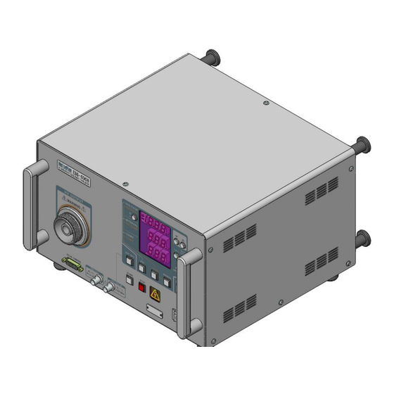
INSTRUCTION MANUAL
ELECTROSTATIC DISCHARGE
SIMULATOR
FOR SEMICONDUCTORS
ESS-6002/6008
MODEL
NOISE LABORATORY CO., LTD.
Edition1.06
AEC00206-00E-0G
Table of
Contents
Previous
Page
Next
Page
1
2
3
4
5
Advertisement
Table of Contents
Need help?
Do you have a question about the ESS-6002 and is the answer not in the manual?
Ask a question
Questions and answers
Related Manuals for NoiseKen ESS-6002
Laboratory Equipment NoiseKen ESS-S3011A Instruction Manual
Electrostatic discharge simulator (98 pages)
Laboratory Equipment NoiseKen ESS-2000AX Instruction Manual
Electrostatic discharge simulator (56 pages)
Laboratory Equipment NoiseKen ESS-801GL Instruction Manual
(23 pages)
Laboratory Equipment NoiseKen ESS-2002EX Instruction Manual
Electrostatic discharge simulator (46 pages)
Laboratory Equipment NoiseKen ESS-6008 Instruction Manual
Electrostatic discharge simulator for semiconductors (44 pages)
Laboratory Equipment NoiseKen ESS-PS1 Instruction Manual
Electrostatic discharge simulator and electrostatic discharge gun (104 pages)
Laboratory Equipment NoiseKen EPS-02Hv2 Instruction Manual
Space-magnetic field visualization system (42 pages)
Laboratory Equipment NoiseKen FNS-AX4-A20 Instruction Manual
Fast transient burst simulator (96 pages)
Laboratory Equipment NoiseKen LSS-6330 Series Instruction Manual
Injection unit for lightning surge simulator (27 pages)
Laboratory Equipment NoiseKen ISS-7610 Instruction Manual
Automotive transient surge simurator (40 pages)
Laboratory Equipment NoiseKen LSS-6330-A20 Instruction Manual
Lightning surge simulator (80 pages)
Laboratory Equipment NoiseKen LSS-6330-A20A Instruction Manual
Lightning surge simulator (80 pages)
Laboratory Equipment NoiseKen IJ-4050 Instruction Manual
Ac line cdn for impulse noise simulator (38 pages)
Laboratory Equipment NoiseKen SWCS-931SD Instruction Manual
Damped-oscillatory wave simulator (28 pages)
Laboratory Equipment NoiseKen LSS-6330-B63A Instruction Manual
Lightning surge simulator (86 pages)
Laboratory Equipment NoiseKen JSS-003 Instruction Manual
Automotive transient surge simulator (32 pages)
This manual is also suitable for:
Ess-6008
Table of Contents
Print
Rename the bookmark
Delete bookmark?
Delete from my manuals?
Login
Sign In
OR
Sign in with Facebook
Sign in with Google
Upload manual
Upload from disk
Upload from URL


Need help?
Do you have a question about the ESS-6002 and is the answer not in the manual?
Questions and answers