Table of Contents
Advertisement
Quick Links
INSTRUCTION MANUAL
INSTRUCTION MANUAL
INSTRUCTION MANUAL
INSTRUCTION MANUAL
INSTRUCTION MANUAL
FAST TRANSIENT BURST SIMULATOR
FAST TRANSIENT BURST SIMULATOR
FAST TRANSIENT BURST SIMULATOR
FAST TRANSIENT BURST SIMULATOR
FAST TRANSIENT BURST SIMULATOR
FNS
FNS-AX4-
FNS
FNS-AX4-
NOISE LABORATORY CO., LTD.
NOISE LABORATORY CO., LTD.
NOISE LABORATORY CO., LTD.
NOISE LABORATORY CO., LTD.
NOISE LABORATORY CO., LTD.
-A20
-B63
Edition1.02
AEH00220-00E-0
AEH00
Advertisement
Table of Contents

Subscribe to Our Youtube Channel
Related Manuals for NoiseKen FNS-AX4-A20


Summary of Contents for NoiseKen FNS-AX4-A20
- Page 1 INSTRUCTION MANUAL INSTRUCTION MANUAL INSTRUCTION MANUAL INSTRUCTION MANUAL INSTRUCTION MANUAL FAST TRANSIENT BURST SIMULATOR FAST TRANSIENT BURST SIMULATOR FAST TRANSIENT BURST SIMULATOR FAST TRANSIENT BURST SIMULATOR FAST TRANSIENT BURST SIMULATOR FNS-AX4- -A20 FNS-AX4- -B63 NOISE LABORATORY CO., LTD. NOISE LABORATORY CO., LTD. NOISE LABORATORY CO., LTD.
- Page 2 NOTICE The contents of this instruction manual (the “Manual”) are subject to change without • prior notice. No part of the Manual may be reproduced or distributed, in any form or by any means, • without the authorization of Noise Laboratory Co., Ltd. (the “Company”). The contents of the Manual have been thoroughly examined.
-
Page 3: Important Safety Precautions
The following instructions are very important for safe handling of the fast transient burst simulator FNS-AX4-A20/B63 (hereinafter “the Unit”). They must be kept strictly to prevent users of the Unit from receiving harm or damage through using the Unit. Read them carefully before use. -
Page 4: Contents In Package
This instruction manual (hereinafter “the Manual”) is available at FNS-AX4-A20 and FNS-AX4-B63. The corresponding model is specified when function is different according to the model. The difference between FNS-AX4-A20 and FNS-AX4-B63 is as follows from the viewpoint of the power capacity of EUT (Equipment Under Test). -
Page 5: Application Form For Instruction Manual
3. APPLICATION FORM FOR INSTRUCTION MANUAL We place an order for an instruction manual. Model: FNS-AX4-A20/B63 Serial No.: Applicant: Company name: Address: Department: Person in charge: Tel No.: Fax No. Cut off this page “APPLICATION FORM FOR INSTRUCTION MANUAL” from this volume and keep it for future use with care. - Page 6 Memorandum...
-
Page 7: Preface
We thank you very much for your purchase of our Fast Transient Burst Simulator FNS-AX4 series (FNS-AX4-A20, FNS-AX4-B63, hereinafter “the Unit”). This instruction manual (“the Manual”) contains how to use the Unit and other important information. In order to obtain the highest performance from the Unit, thoroughly understand the contents of the Manual and use as ready reference for operation. -
Page 8: Table Of Contents
5. TABLE OF CONTENTS 1. IMPORTANT SAFETY PRECAUTIONS ..............1 2. CONTENTS IN PACKAGE ..................2 3. APPLICATION FORM FOR INSTRUCTION MANUAL ..........3 4. PREFACE ........................5 4-1. P ···························································································· 5 REFACE 4-2. F ···························································································· 5 EATURE 5. TABLE OF CONTENTS ..................... 6 6. - Page 9 5. TABLE OF CONTENTS 10-5. C ······························································ 29 ONNECTING OUPLING LAMP 10-3. C ······································································ 30 ONNECTING NPUT 10-4. C ) ················································· 32 ONNECTING UTPUT OWER 11. OPERATION ......................34 11-1. T ON FNS-AX4 ············································································ 34 11-2. E ··································································· 34 MERGENCY UTTON How to cancel emergency stop ....................
- Page 10 5. TABLE OF CONTENTS Load ............................59 Delete ............................59 13-4. E ····································································· 60 XECUTING ANUAL 14. SETTING UP SEQUENCE TEST ................64 14-1. M ························································ 65 AKING EQUENCE XECUTION 14-2. S ························································ 67 AVING EQUENCE XECUTION Save ............................68 Load ............................
- Page 11 5. TABLE OF CONTENTS Waveform Verification with 50Ω Load (In Case of Using 00-00017A) ........85 Waveform Verification with 1kΩ Load (In Case of Using 00-00018A) ........85 ) ···· 87 21-2. V EUT LINE OUT(W 50Ω L ERIFICATION AT AVEFORM ERIFICATION WITH 21-3.
-
Page 12: Basic Safety Precautions
6. BASIC SAFETY PRECAUTIONS The following items are very important instructions which users must follow to take precautions against possible injury and harm. The indications are provided as an explanation of potential danger involved if the safety precautions are not observed correctly. 6-1. - Page 13 6. BASIC SAFETY PRECAUTI 6. BASIC SAFETY PRECAUTI 6. BASIC SAFETY PRECAUTI 6. BASIC SAFETY PRECAUTIONS The contents of following signs indicate warnings and cautions when using the Unit. The contents of following signs indicate warnings and cautions when using the Unit. The contents of following signs indicate warnings and cautions when using the Unit.
-
Page 14: Danger
6. BASIC SAFETY PRECAUTIONS 6-3. Danger Do not take the Unit apart or do not remodel. Do not open the cover. Imminent danger might occur resulting in death or serious injury. Repair, internal adjustment, and inspection of the Unit should be performed by a qualified service Do not engineer. - Page 15 6. BASIC SAFETY PRECAUTIONS Do not supply over-rating power to EUT Line input terminal. Do not supply over-rating power to EUT line. The misuse may cause a damage of equipment or a fire. The rating of input is; A20: Maximum voltage: AC240 V, DC125 V, Maximum current 20 A (PE line: 10 A);...
-
Page 16: Caution
6. BASIC SAFETY PRECAUTIONS Do not use the attached AC cord for any other purpose. The misuse may result in a fire or an electric shock. Do not damage AC cord. A damaged AC cord may cause a fire or an electric shock. For HV cable, be sure to take notice following points. - Page 17 6. BASIC SAFETY PRECAUTIONS When the body is dirty, wipe the body with a dry cloth. Do not wipe the Unit and Probe with thinner, alcohol or other solvent. When the body is very dirty, soak a cloth into neutral detergent, squeeze out the detergent from the cloth and wipe the body with the cloth.
-
Page 18: Caution About Expendable Supplies
7. CAUTION ABOUT EXPENDABLE SUPPLIES 7. CAUTION ABOUT EXPENDABLE SUPPLIES 7. CAUTION ABOUT EXPENDABLE SUPPLIES 7. CAUTION ABOUT EXPENDABLE SUPPLIES 7. CAUTION ABOUT EXPENDABLE SUPPLIES 7. CAUTION ABOUT EXPENDABLE SUPPLIES 7. CAUTION ABOUT EXPENDABLE SUPPLIES About a high voltage relay inside About a high voltage relay inside About a high voltage relay inside About a high voltage relay inside... -
Page 19: Introductory Notes
8. INTRODUCTORY NOTES 8-1. Introductory Notes The meaning of following symbols is as follows. Operate the touch panel. Additional explanation. Indicating other parts to be referred in the Manual. Indicating restriction of setting up. Indicating items to be confirmed before usage. 【... -
Page 20: Characteristics Of Burst Generator
8. INTRODUCTORY NOTES 8-3. Characteristics of Burst Generator The burst waveform output by the Unit is shown as Fig. 8-1. The waveform of single pulse is prescribed with 50Ω load and 1kΩ load, shown as Fig, 8-2. PULSE BURST Output timing prescribed in IEC 61000-4-4 Pulse frequency 5 kHz 100 kHz... - Page 21 8. INTRODUCTORY NOTES 8-4. Block Diagram of FNS-AX4 Pulse generator BURST GENERATOR PULSE OUT (50Ω coaxial) HVPS to CDN from BURST GENERATOR CDN (A20) EUT LINE IN EUT LINE OUT Contactor terminal (EUT LINE SW) terminal Ferrites SG trminal from BURST GENERATOR CDN (B63) EUT LINE IN EUT LINE OUT...
-
Page 22: Fns-Ax4
8. INTRODUCTORY NOTES 8. INTRODUCTORY NOTES 8. INTRODUCTORY NOTES 8-5. Examle of Test 5. Examle of Test IEC 61000- -4-4 prescribes test to check immunity of EUT against burst noise 4 prescribes test to check immunity of EUT against burst noise 4 prescribes test to check immunity of EUT against burst noise occurred 4 prescribes test to check immunity of EUT against burst noise 4 prescribes test to check immunity of EUT against burst noise... -
Page 23: Example Of Test To Signal Line
8. INTRODUCTORY NOTES 8. INTRODUCTORY NOTES 8. INTRODUCTORY NOTES 8. INTRODUCTORY NOTES Example of Test to Signal Line Example of Test to Signal Line Example of Test to Signal Line Example of Test to Signal Line Put the Unit (FNS Put the Unit (FNS- -AX4) on ground plane (ground reference plane) which is connected to protective ) on ground plane (ground reference plane) which is connected to protective... -
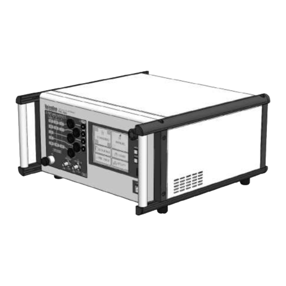
Page 24: Appearance And Function Of Each Part
9. APPEARANCE AND FUNCTION OF EACH PART 9. APPEARANCE AND FUNCTION OF EACH PART 9. APPEARANCE AND FUNCTION OF EACH PART 9. APPEARANCE AND FUNCTION OF EACH PART 9. APPEARANCE AND FUNCTION OF EACH PART 9. APPEARANCE AND FUNCTION OF EACH PART 9. -
Page 25: Control Panel
9. APPEARANCE AND FUNCTION OF EACH PART 9-2. Control Panel Emergency stop button 【 EMERGENCY STOP 】 Stop button for emergency. Avoid using this button for ordinary stop. EUT LINE switch 【 EUT LINE 】 Used to turn ON/OFF EUT LINE which is used for power line test. Note) Status of EUT LINE will be held even after stopping test. -
Page 26: Output Panel
9. APPEARANCE AND FUNCTION OF EACH PART 9-3. Output panel EUT line output terminals 【 EUT LINE OUTPUT 】 EUT line output terminal of L1/L2/L3/N/PE(B63) or L/N/PE(A20). The EUT shall be connected to EUT LINE OUTPUT ports by using the supplied line output cables The EUT LINE OUTPUT and the accessory cables adopt Snap-in lock system connector by Staubli Electrical Connectors AG. - Page 27 9. APPEARANCE AND FUNCTION OF EACH PART SG terminal 【 SG 】 Signal ground which becomes a return loop of high voltage pulse. Connect it to ground plane with the attached SG cable. Pulse out connector 【 PULSE OUT 】 Coaxial connector outputting high voltage pulse.
-
Page 28: Rear Panel
9. APPEARANCE AND FUNCTION OF EACH PART 9-4. Rear Panel Used to radiate internal heat. Avoid blocking ventilation. Communication port for servicing 【 EXCLUSIVE USE 】 Connector dedicated only to maintenance/servicing. Do not remove cover. Warning lamp/pilot lamp port 【 INDICATOR 】 An optional waring lamp or tri-color pilot light can be connected. - Page 29 9. APPEARANCE AND FUNCTION OF EACH PART EUT line input terminal 【 EUT LINE INPUT 】 Safety sockets used for inputting power supply for EUT. EUT line of the Unit does not have any protection circuit against over voltage or over current. Prepare a proper protection circuit separately.
-
Page 30: Connection
10. CONNECTION 10-1. Connecting AC Cord Insert a proper AC cord into AC inlet 【 AC INPUT 】 . The attached AC cord is for AC100~120 V. In case of AC220~240 V, prepare a 3-line AC cord with PE terminal pin which is conforming to the local safety standard. 10-2. -
Page 31: Connecting Coupling Clamp
10. CONNECTION 10. CONNECTION 10. CONNECTION 10-5. Connecting Coupling Clamp 5. Connecting Coupling Clamp 5. Connecting Coupling Clamp 5. Connecting Coupling Clamp Connect coupling clamp (option) to the Unit. For configuration of equipment, refer to the instruction Connect coupling clamp (option) to the Unit. For configuration of equipment, refer to the instruction Connect coupling clamp (option) to the Unit. -
Page 32: Connecting Line Input
10. CONNECTION 10. CONNECTION 10-3. Connecting Line Input 3. Connecting Line Input 3. Connecting Line Input Connect EUT power supply to the Unit. Connect EUT power supply to the Unit. Connect EUT power supply to the Unit. Connect EUT power supply to the Unit. The EUT supply connection shall be made by using the EUT supply connection shall be made by using the EUT supply connection shall be made by using the... - Page 33 10. CONNECTION A20 type Single-phase (AC) B63 type When B63 type is used to test either single phase AC or DC operated EUT, EUT connection shall be made at EUT LINE INPUT marked【AC 1PHASE】 【DC】. Single-phase 3-phase 5-line (AC) Do not force the plug to disconnect without unlocking. It results in damaging both LINE OUTPUT Connector socket and cable plug.
-
Page 34: Connecting Line Output (Power Line)
10. CONNECTION 10. CONNECTION 10-4. Connecting Line Output (Power Line) 4. Connecting Line Output (Power Line) 4. Connecting Line Output (Power Line) 4. Connecting Line Output (Power Line) 4. Connecting Line Output (Power Line) Connect line output cables. The points to Connect line output cables. - Page 35 10. CONNECTION A20 type Single-phase (AC) B63 type Single-phase 3-phase 5 line(AC) The EUT side of the LINE OUTPUT cables is with an M6 solderless terminal.
-
Page 36: Operation
11. OPERATION 11. OPERATION 11. OPERATION 11-1. Turn ON FNS 1. Turn ON FNS-AX Turn on the Unit Turn on the Unit with POWER switch on front panel of the Unit. with POWER switch on front panel of the Unit. with POWER switch on front panel of the Unit. -
Page 37: Main Menu
11. OPERATION 11. OPERATION 11. OPERATION 11-3. Main Menu Main Menu The Unit adopts touch panel type LCD which enables image The Unit adopts touch panel type LCD which enables image The Unit adopts touch panel type LCD which enables image The Unit adopts touch panel type LCD which enables image The Unit adopts touch panel type LCD which enables image The Unit adopts touch panel type LCD which enables image-oriented operation with graphic display. -
Page 38: Screen Flowchart
11. OPERATION 11-4. Screen Flowchart Standard test mode(POWER LINE ⇔ SIGNAL LINE) Main menu Manual test mode CDN setting screen Sweep setting sceen CDN sweep setting screen Title operation screen Special function setting screen Sequence test mode Sequence title operation screen UTIL1 UTIL2 UTIL3... -
Page 39: Inputting Numbers And Letters (About Ten Key And Character Key)
11. OPERATION 11-5. Inputting Numbers and Letters (About Ten Key and Character Key) Ten key is displayed for inputting numbers, character key is displayed for operation for title. Basic operations of them are as follows. Touch the item to be input to display ten key. Ten key will be displayed with the value as before. [Title of input items] Indicates pulse voltage, pulse frequency, burst duration, burst period, etc. -
Page 40: Setting Up Standard Test
12. SETTING UP STANDARD TEST 12. SETTING UP STANDARD TEST 12. SETTING UP STANDARD TEST 12. SETTING UP STANDARD TEST 12. SETTING UP STANDARD TEST Touch 『 『 STANDARD STANDARD 』 on main me on main menu. In Standard test mode, the test levels shown on Table 12 In Standard test mode, the test levels shown on Table 12 In Standard test mode, the test levels shown on Table 12 In Standard test mode, the test levels shown on Table 12... - Page 41 12. SETTING UP STANDARD TEST 12. SETTING UP STANDARD TEST 12. SETTING UP STANDARD TEST 12. SETTING UP STANDARD TEST 12. SETTING UP STANDARD TEST Output Output Indicates which high voltage pulse Indicates which high voltage pulse Indicates which high voltage pulse Indicates which high voltage pulse outputs to, CDN or Pulse out.
-
Page 42: Selecting Coupling Line
12. SETTING UP STANDARD TEST 12. SETTING UP STANDARD TEST 12. SETTING UP STANDARD TEST 12. SETTING UP STANDARD TEST Selecting Coupling Line Selecting Coupling Line Selecting Coupling Line Select 『 POWER LINE POWER LINE 』 or 『 SIGNAL LINE SIGNAL LINE 』... -
Page 43: Executing Standard Test
12. SETTING UP STANDARD TEST 12. SETTING UP STANDARD TEST 12. SETTING UP STANDARD TEST 12. SETTING UP STANDARD TEST 12. SETTING UP STANDARD TEST 12-1. Executing Standard Test 1. Executing Standard Test 1. Executing Standard Test Power supply to EUT Power supply to EUT Power supply to EUT In case of test to power line, press EUT LINE switch 【... - Page 44 12. SETTING UP STANDARD TEST 12. SETTING UP STANDARD TEST 12. SETTING UP STANDARD TEST 12. SETTING UP STANDARD TEST Conducting test Conducting test 『 UNDER TEST UNDER TEST 』 is indicated upper right on the screen. While test is being conducted, START switch is indicated upper right on the screen.
- Page 45 12. SETTING UP STANDARD TEST 12. SETTING UP STANDARD TEST 12. SETTING UP STANDARD TEST 12. SETTING UP STANDARD TEST 12. SETTING UP STANDARD TEST Completion of test Completion of test Test is completed automatically when the set time has passed. START switch lights off and 『 Test Test is completed automatically when the set time has passed.
-
Page 46: Setting Up Manual Test
13. SETTING UP MANUAL TEST 13. SETTING UP MANUAL TEST 13. SETTING UP MANUAL TEST 13. SETTING UP MANUAL TEST 13. SETTING UP MANUAL TEST Touch 『 『 MANUAL 』 』 on main menu. on main menu. ☆ Title Title Manual test setting screen Manual test setting screen Manual test setting screen... -
Page 47: Selecting Polarity
13. SETTING UP MANUAL TEST 13. SETTING UP MANUAL TEST 13. SETTING UP MANUAL TEST 13. SETTING UP MANUAL TEST Selecting Selecting Polarity Polarity Touch Touch Setting Pulse Voltage Setting Pulse Voltage Setting Pulse Voltage Touch the column of voltage. Touch the column of voltage. -
Page 48: Setting Number Of Pulse
13. SETTING UP MANUAL TEST 13. SETTING UP MANUAL TEST 13. SETTING UP MANUAL TEST Setting Number of Pulse Setting Number of Pulse Setting Number of Pulse Touch the column of pulse count. Touch the column of pulse count. Touch the column of pulse count. Touch the column of pulse count. - Page 49 13. SETTING UP MANUAL TEST Summary of setting burst Pulse count is less than 1 per 1 ms of burst period. Burst duration = Pulse count / Pulse frequency Burst duration < Burst period Ex. 1) Npmax Np: Pulse count Npmax: Max.
-
Page 50: Selecting Cdn Out Or Pulse Out
13. SETTING UP MANUAL TEST 13. SETTING UP MANUAL TEST 13. SETTING UP MANUAL TEST Selecting CDN Out or Pulse Out Selecting CDN Out or Pulse Out Selecting CDN Out or Pulse Out Selecting CDN Out or Pulse Out Touch Touch is touched, CDN setting screen is indicated. - Page 51 13. SETTING UP MANUAL TEST Example of AC line synchronized output (1) Phase angle: 90 ° T=20ms(AC50Hz) :AC line cycle :Burst duration :Burst period After outputting under the condition of the specified burst duration and period, the next burst is output again on the next synchronized timing of AC line.
-
Page 52: Setting Test Time
13. SETTING UP MANUAL TEST 13. SETTING UP MANUAL TEST 13. SETTING UP MANUAL TEST Setting CDN coupling phase Setting CDN coupling phase Setting CDN coupling phase Setting CDN coupling phase Select phases to be coupled and touch the phase. Select phases to be coupled and touch the phase. -
Page 53: Sweep Mode
13. SETTING UP MANUAL TEST 13. SETTING UP MANUAL TEST 13. SETTING UP MANUAL TEST 13. SETTING UP MANUAL TEST 13-1. Sweep Mode 1. Sweep Mode A test with using the sweep function is useful A test with using the sweep function is useful A test with using the sweep function is useful A test with using the sweep function is useful A test with using the sweep function is useful to check malfunction level of EUT because,... -
Page 54: Setting Polarity Sweep
13. SETTING UP MANUAL TEST 13. SETTING UP MANUAL TEST 13. SETTING UP MANUAL TEST Setting Polarity Sweep Setting Polarity Sweep Setting Polarity Sweep If polarity sweep is set, the test is conducted in order of positive (+) If polarity sweep is set, the test is conducted in order of positive (+) If polarity sweep is set, the test is conducted in order of positive (+) If polarity sweep is set, the test is conducted in order of positive (+) If polarity sweep is set, the test is conducted in order of positive (+) -
Page 55: Setting Cdn Sweep
13. SETTING UP MANUAL TEST 13. SETTING UP MANUAL TEST 13. SETTING UP MANUAL TEST 13. SETTING UP MANUAL TEST Setting CDN Sweep Setting CDN Sweep Setting CDN Sweep Touch on Sweep setting screen to indicate CDN sweep setting screen. On this screen, line on Sweep setting screen to indicate CDN sweep setting screen. -
Page 56: Special Functions
13. SETTING UP MANUAL TEST 13. SETTING UP MANUAL TEST 13. SETTING UP MANUAL TEST 13-2. Special Functions 2. Special Functions 2. Special Functions A test with using special functions is effective to reproduce EUT A test with using special functions is effective to reproduce EUT A test with using special functions is effective to reproduce EUT A test with using special functions is effective to reproduce EUT A test with using special functions is effective to reproduce EUT... -
Page 57: Setting Continuous Output
13. SETTING UP MANUAL TEST Setting Continuous Output Burst can be output continuously irrelevant to burst period with the continuous output function. Touch ON/OFF of CONTINUOUS. The following conditions are necessary to make the continuous output function effective. Available pulse frequency is limited according to voltage value. Set them within the following range. •... -
Page 58: Setting External Trigger
13. SETTING UP MANUAL TEST Setting External Trigger Burst can be output synchronized with an external signal. When a signal is input to the external trigger connector on control panel 【 EXT TRIG IN 】 , the set burst is output. -
Page 59: Title Save / Load
13. SETTING UP MANUAL TEST 13. SETTING UP MANUAL TEST 13. SETTING UP MANUAL TEST 13. SETTING UP MANUAL TEST 13-3. Title Save / Load 3. Title Save / Load 3. Title Save / Load The set up test contents can be saved with naming a title. Saving 30 kinds of sets is available and each The set up test contents can be saved with naming a title. -
Page 60: Save
13. SETTING UP MANUAL TEST 13. SETTING UP MANUAL TEST 13. SETTING UP MANUAL TEST Save Touch a title box for saving and touch Touch a title box for saving and touch Touch a title box for saving and touch Touch a title box for saving and touch to indicate character key. -
Page 61: Load
13. SETTING UP MANUAL TEST Load Load means calling the saved titled file to use it for manual test set up. Touch the title box to be called. Touch to call the saved test contents. If there is another set up in editing on Manual test setting screen, a check box as below appears before start loading. -
Page 62: Executing Manual Test
13. SETTING UP MANUAL TEST 13. SETTING UP MANUAL TEST 13. SETTING UP MANUAL TEST 13-4. Executing Manual Test 4. Executing Manual Test 4. Executing Manual Test Power supply to EUT Power supply to EUT Power supply to EUT In case of test to power line, press EUT LINE switch 【 【... - Page 63 13. SETTING UP MANUAL TEST 13. SETTING UP MANUAL TEST 13. SETTING UP MANUAL TEST 13. SETTING UP MANUAL TEST Check screen when ck screen when “SWEEP SWEEP” is set is set Pulse frequency Pulse frequency sweep Pulse voltage sweep Pulse voltage sweep Phase angle sweep Phase angle sweep...
- Page 64 13. SETTING UP MANUAL TEST 13. SETTING UP MANUAL TEST 13. SETTING UP MANUAL TEST Pause Pressing START switch while conducting test makes the output pausing. START switch is blinking and Pressing START switch while conducting test makes the output pausing. START switch is blinking and Pressing START switch while conducting test makes the output pausing.
- Page 65 13. SETTING UP MANUAL TEST 13. SETTING UP MANUAL TEST 13. SETTING UP MANUAL TEST 13. SETTING UP MANUAL TEST Moving to next test Moving to next test Moving to next test In case of c In case of conducting a sequence test or a test set Sweep function, the following message is indicated onducting a sequence test or a test set Sweep function, the following message is indicated onducting a sequence test or a test set Sweep function, the following message is indicated onducting a sequence test or a test set Sweep function, the following message is indicated...
-
Page 66: Setting Up Sequence Test
14. SETTING UP SEQUENCE TEST 14. SETTING UP SEQUENCE TEST 14. SETTING UP SEQUENCE TEST 14. SETTING UP SEQUENCE TEST 14. SETTING UP SEQUENCE TEST Touch 『 『 SEQUENCE SEQUENCE 』 on main menu. on main menu. 『 SEQUENCE SEQUENCE 』 is the function to conduct test contents one after another which are saved on Manual is the function to conduct test contents one after another which are saved on Manual is the function to conduct test contents one after another which are saved on Manual is the function to conduct test contents one after another which are saved on Manual... -
Page 67: Making Sequence Execution List
14. SETTING UP SEQUENCE TEST 14. SETTING UP SEQUENCE TEST 14. SETTING UP SEQUENCE TEST 14. SETTING UP SEQUENCE TEST 14. SETTING UP SEQUENCE TEST 14-1. Making Sequence Execution List 1. Making Sequence Execution List 1. Making Sequence Execution List 1. - Page 68 14. SETTING UP SEQUENCE TEST 14. SETTING UP SEQUENCE TEST 14. SETTING UP SEQUENCE TEST 14. SETTING UP SEQUENCE TEST Deleting a title from the sequence execution list Deleting a title from the sequence execution list Deleting a title from the sequence execution list Deleting a title from the sequence execution list Deleting a title from the sequence execution list Deleting a title from the sequence execution list...
-
Page 69: Saving Sequence Execution List
14. SETTING UP SEQUENCE TEST 14. SETTING UP SEQUENCE TEST 14. SETTING UP SEQUENCE TEST 14. SETTING UP SEQUENCE TEST 14. SETTING UP SEQUENCE TEST 14-2. Saving Sequence Execution List 2. Saving Sequence Execution List 2. Saving Sequence Execution List 2. -
Page 70: Save
14. SETTING UP SEQUENCE TEST 14. SETTING UP SEQUENCE TEST 14. SETTING UP SEQUENCE TEST 14. SETTING UP SEQUENCE TEST Save Touch the sequence title box to be saved and touch Touch the sequence title box to be saved and touch Touch the sequence title box to be saved and touch Touch the sequence title box to be saved and touch Touch the sequence title box to be saved and touch... -
Page 71: Load
14. SETTING UP SEQUENCE TEST Load Load means calling the saved sequence title to use it for sequence test set up. Touch the title box to be called. Touch to call the saved sequence title. If there is another set up in editing on Sequence test setting screen, a check box as below appears before start loading. -
Page 72: Executing Sequence Test
14. SETTING UP SEQUENCE TEST 14. SETTING UP SEQUENCE TEST 14. SETTING UP SEQUENCE TEST 14. SETTING UP SEQUENCE TEST 14-3. Executing Sequence Test 3. Executing Sequence Test 3. Executing Sequence Test 3. Executing Sequence Test Sequence test can start on Sequence setting screen. If the sequence test execution list has any title, the Sequence test can start on Sequence setting screen. -
Page 73: Utility
15. UTILITY 15. UTILITY 15. UTILITY Touch 『 『 UTILITY 』 』 on main menu. on main menu. Some items which are not related with test parameters directly Some items which are not related with test parameters directly Some items which are not related with test parameters directly Some items which are not related with test parameters directly Some items which are not related with test parameters directly can be set as you like depending on Some items which are not related with test parameters directly... -
Page 74: Burst Alarm Beep
15. UTILITY 15. UTILITY Burst Alarm Beep Burst Alarm Beep Burst Alarm Beep Selects whether an alarm sound beeps or not when test is conducted. Selects whether an alarm sound beeps or not when test is conducted. Selects whether an alarm sound beeps or not when test is conducted. Selects whether an alarm sound beeps or not when test is conducted. -
Page 75: Sequence Method
15. UTILITY 15. UTILITY 15. UTILITY Sequence Sequence Method Method Selects how to switch to the next stage when sequence test is selected. Selects how to switch to the next stage when sequence test is selected. Selects how to switch to the next stage when sequence test is selected. Selects how to switch to the next stage when sequence test is selected. -
Page 76: Pre Check
16. PRE CHECK 16. PRE CHECK 16. PRE CHECK The PRECHECK function is provided for the use The PRECHECK function is provided for the use The PRECHECK function is provided for the use The PRECHECK function is provided for the use The PRECHECK function is provided for the users to easily check whether pulse outputs are available at rs to easily check whether pulse outputs are available at rs to easily check whether pulse outputs are available at... - Page 77 16. PRE CHECK 16. PRE CHECK 16. PRE CHECK Ports connection and performing orts connection and performing a PRECHCK orts connection and performing orts connection and performing a PRECHCK Connect the Connect the selected port selected port (PULSE OUT/either of EUT LINE OUTPUT) to PRECHE (PULSE OUT/either of EUT LINE OUTPUT) to PRECHE (PULSE OUT/either of EUT LINE OUTPUT) to PRECHE (PULSE OUT/either of EUT LINE OUTPUT) to PRECHE...
-
Page 78: Other Functions
17. OTHER FUNCTIONS 17-1. EUT FAIL Function With inputting a signal to EUT FAIL terminal, control, such as stopping or pausing, is available externally. The function can be utilized when EUT malfunctions. The Unit does not have any function to judge EUT’s malfunction. EUT FAIL signal should be prepared in user’s side. -
Page 79: Connection Of Indicator
7. OTHER FUNCTIONS . OTHER FUNCTIONS . OTHER FUNCTIONS 17-2. Connection of indicator Connection of indicator Connection of indicator Warning Lamp/ Tri Warning Lamp/ Tri-color pilot light color pilot light color pilot light is optionally available. is optionally available. When using an either option, connect to 【INDICATOR 】connector on When using an either option, connect to When using an either option, connect to... -
Page 80: Ormal Mode Testing Using Optional 15-00013A
17. OTHER FUNCTIONS Normal mode testing(using optional 15-00013A) Capable of conducting normal mode noise injection testing conforming to ANSI/IEEE C37.90.1 by using an optional normal mode coupling balun.The normal mode coupling balun is the adaptor converting the common mode output of the simulator (the ground side of PULSE OUT is connected to the pulse signal ground) into floating output (the HIGH and LOW sides working against each other where ground is irrelevant) Coupling Balun 15-00013A... - Page 81 17. OTHER FUNCTIONS Connect the EUT to the simulator. EUT LINE OUTPUT ports selected in step 3 should be used. Turn of the simulator POWER. Perform the required test settings following the instructions in earlier pages. When testing in this mode, the PULSE OUT port should be active.
-
Page 82: Returning To Initial Setting
17. OTHER FUNCTIONS 17-3. Returning to Initial Setting To return the whole setting to the initial setting in shipment, turn ON POWER switch 【 POWER 】 with pressing MENU switch 【 MENU 】 When a user uses this function, all contents set on standard, manual, and sequence test screen and on utility screen are deleted simultaneously. -
Page 83: Error Message
18. ERROR MESSAGE Errors indicated on the Unit are shown as below table. Err No. Indication Meaning Emergency stop button was pressed. EMERGENCY STOP The Unit cannot be operated. ERROR1 CHECK SAFETY After confirming safety, turn on again. (For details, refer to P. 34) Repair is necessary. -
Page 84: Specifications
19. SPECIFICATIONS 19-1. Specifications of Generator Item Specifications 200 V ~ 5000 V Output voltage 10 V step Polarity Positive and negative 0.1 kHz ~ 2000 kHz Pulse Frequency ~ 1 kHz 0.1 kHz /0.01 kHz Step ~ 10 kHz 1.0 kHz /0.1 kHz Step... -
Page 85: Specifications Of
19. SPECIFICATIONS 19-2. Specifications of CDN Item Specifications A20: Single-phase AC240 V/20 A, DC125 V/20 A ( PE: 10 A ) EUT Power capacity B63: 3-phase AC600 V/63 A, DC125 V/63 A ( N/PE: 10 A ) Coupling phase A20: L/N/PE B63: L1/L2/L3/N/PE Each line, All lines, Combinations of lines Coupling mode... -
Page 86: Optional Products
20. OPTIONAL PRODUCTS Major optional products are as follows. For details, enquire Noise Laboratory or your nearest sales agent of Noise Laboratory. Items MODEL No. Remarks Capacitive coupling clamp conforming to IEC61000-4-4. Coupling clamp 15-00012A Dedicated coupling clamp calibration fixture (15-00010A) also available Attenuator to observe output waveform. -
Page 87: Waveform Verification
21. WAVEFORM VERIFICATION Preparation Oscilloscope (Frequency range: DC~500 MHz or more) Attenuator 00-00017A: Optional product (Input impedance: 50 Ω , Output Impedance: 50 Ω , Attenuation: 40 dB) Attenuator 00-00018A: Optional product (Input impedance: 50 Ω , Output Impedance: 50 Ω , Attenuation: 60 dB) CDN waveform verification connector 21-1. - Page 88 21. WAVEFORM VERIFICATION For observing waveform on an oscilloscope with connecting load resistance, the actual output voltage and the input restriction of the oscilloscope should be checked previously. The output voltage of the pulse to be observed can be found with applying the following 〔Formula 1〕.
-
Page 89: Verification At Eut Line Out(Waveform Verification With 50Ω Load
21. WAVEFORM VERIFICATION . WAVEFORM VERIFICATION . WAVEFORM VERIFICATION . WAVEFORM VERIFICATION 21-2. Verification at EUT LINE OUT 2. Verification at EUT LINE OUT 2. Verification at EUT LINE OUT 2. Verification at EUT LINE OUT(Waveform Verification with 50 Waveform Verification with 50Ω Load Waveform Verification with 50 Waveform Verification with 50 Load)... -
Page 90: Waveform For Reference
21. WAVEFORM VERIFICATION . WAVEFORM VERIFICATION . WAVEFORM VERIFICATION ② Connect the CDN Connect the CDN waveform waveform verification connector verification connector verification connector to the input connector of 00 to the input connector of 00 to the input connector of 00 to the input connector of 00-00017A with a coaxial 00017A with a coaxial 00017A with a coaxial... -
Page 91: Warranty
22. WARRANTY Servicing terms The following terms are applicable to servicing by Noise Laboratory Co., Ltd., (hereafter referred to as the Company) provided to maintain the intended performance of its products. 1. Scope The following terms shall apply only to products made by the Company. 2. - Page 92 22. WARRANTY Limited warranty Noise Laboratory Co., Ltd. (hereafter referred to as the Company) warrants its products to be free from defects in materials and workmanship under normal use and service for a period of one year from date of delivery. In the event of failure of a product covered by this warranty, the Company will repair the product or may, at its option, replace it in lieu of repair without charge.
-
Page 93: Maintenance
23. MAINTENANCE When repair, maintenance or internal adjustment of the unit is required, a qualified service engineer takes charge of such work. Maintenance on the user side is restricted to the outside cleaning and functional check of the unit. When checking or replacing the fuse, turn off the switch of the unit and disconnect the plug socket beforehand. -
Page 94: Noise Laboratory Support Network
NOISE LABORATORY CO., LTD. SALES DEPT. TEL: +81-42-712-2051 FAX +81-42-712-2050 E-mail: sales@noiseken.com http://www.noiseken.com... -
Page 95: Information For Ce Marking, Eu And European Territories
Information for CE Marking, EU and European territories Manufacture: Noise Laboratory Co., Ltd 1-4-4, Chiyoda, Chuo-ku, Sagamihara City, Kanagawa Pref., 252-0237, Japan Importers: Territory: Germany, Austria, Benelux and Eastern Europe DHS Elmea Tools GmbH Main Office Carl-Zeiss-Strasse 43 63322 Roedermark, Germany DHS Elmea Tools GmbH Office Tulln/Austria Bruedergass 1-3, Top B14 3430 Tulln, Austria... - Page 96 NOISE LABORATORY CO., LTD. 1-4-4, Chiyoda, Chuo-ku, Sagamihara City, Kanagawa Pref., 252-0237, Japan TEL: +81-42-712-2051 FAX: +81-42-712-2050 URL: http://www.noiseken.co.jp Printed in Japan...
Need help?
Do you have a question about the FNS-AX4-A20 and is the answer not in the manual?
Questions and answers