
Subscribe to Our Youtube Channel
Related Manuals for NoiseKen SWCS-931SD


Summary of Contents for NoiseKen SWCS-931SD
- Page 1 INSTRUCTION MANUAL DAMPED-OSCILLATORY WAVE SIMULATOR SWCS-931SD NOISE LABORATORY CO., LTD. 1 . 1 1 e d i t i o n A E H 0 0 0 0 5 - 0 0 E - 0 L...
- Page 2 NOTICE • The contents of this instruction manual are subject to change without prior notice. • No part of this instruction manual may be reproduced or distributed, in any form or by any means, without the authorization of Noise Laboratory Co., Ltd. •...
-
Page 3: Important Safety Precautions
1. IMPORTANT SAFETY PRECAUTIONS The following instructions are very important for safe handling of the Damped-oscillatory wave simulator SWCS-931SD (hereinafter “the Unit”). They must be kept strictly to prevent users of the Unit from receiving harm or damage through using the Unit. - Page 4 Memorandum...
-
Page 5: Application Form For Instruction Manual
2. APPLICATION FORM FOR INSTRUCTION MANUAL To: Noise Laboratory Co., Ltd. We place an order for an instruction manual. Model: SWCS-931SD Serial No.: Applicant: Company name: Address: Department: Person in charge: Tel No.: Fax No.: Cut off this page "... - Page 6 Memorandum...
-
Page 7: Table Of Contents
3. TABLE OF CONTENTS 1. IMPORTANT SAFETY PRECAUTIONS ······················································· 1 2. APPLICATION FORM FOR INSTRUCTION MANUAL····································· 3 3. TABLE OF CONTENTS ············································································ 5 4. PREFACE ······························································································ 6 5. BASIC SAFETY PRECAUTIONS ································································ 8 5-1. Warning signs and their meanings ··························································· 8 5-2. -
Page 8: Preface
4. PREFACE W e t h a n k y o u v e r y m u c h f o r b u y i n g S W C S - 9 3 1 S D . T h i s I n s t r u c t i o n M a n u a l c o n t a i n s i m p o r t a n t i n f o r m a t i o n o n t h e f u n c t i o n , o p e r a t i n g p r o c e d u r e a n d o p e r a t i n g p r e c a u t i o n s o f y o u r S W C S - 9 3 1 S D u n i t . - Page 9 Memorandum...
-
Page 10: Basic Safety Precautions
5. BASIC SAFETY PRECAUTIONS 5-1.Warning signs and their meanings Means a warning. WARNING 警告 If such a danger is not avoided, a potential danger which may result in a death or serious injury will be caused. Means a caution. If such a danger is not avoided, a potential danger which may result in a minor or medium degree of injury will be caused. - Page 11 5.BASIC SAFETY PRECAUTIONS WARNING 警告 6. Be extremely careful of an electric shock due to the generated surges. 【 【 【 【 Precautions for human body and operation】 】 】 】 7. As high voltages are generated in the unit, do not open the cover of this unit. Touching inside the unit may cause an electric shock hazard.
- Page 12 5.BASIC SAFETY PRECAUTIONS WARNING 警告 15. The AC INPUT (AC inlet) terminals on the rear panel has a terminal for safety grounding connection. The GND terminal on the front panel is the signal ground terminal for the surge generator circuitry. For connection details, refer to “7.
- Page 13 5.BASIC SAFETY PRECAUTIONS 23. If condensation is found, fully dry the unit before operating it, otherwise, the unit may be damaged or only exhibit limited performance. 【 【 【 【 Precautions for environments】 】 】 】 24. Avoid using this unit in a humid or dusty place, otherwise, the unit may be damaged or only exhibit limited performance.
-
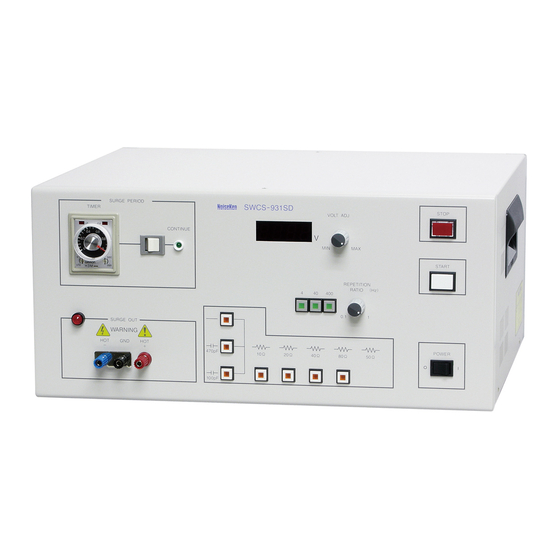
Page 14: Name And Function Of Each Part Of This Unit
6. NAME AND FUNCTION OF EACH PART OF THIS UNIT 【 Front panel 】 ⑨ ⑧ ⑦ ⑥ ⑤ ④ ③ S U R G E P E R I O D S W C S - 9 3 1 S D T I M E R S T O P V O L T . - Page 15 ⑦ : “ ② C O N T I N U E l a m p A l i g h t w h i l e s e l e c t i n g C O N T I N U E m o d e . I n t h i s m o d e , p r e s s i n g ”...
- Page 16 【 Rear panel 】 A C 1 0 0 V ~ 2 4 0 V ± 1 0 % 検 査 合 格 証 C E R T I F I C A T E N O I S E L A B O R A T O R Y C O . , L T D . S / N M A D E I N J A P A N ⑮...
-
Page 17: Accessories
7. ACCESSORIES Before using the instrument, please check that none of the associated items are missing. ・ A C i n p u t c a b l e · · · · · · · · · · · · · · · · · · · · · · · · · · · · · · · · · · · · · · · · · · · · · · · · · · · · · · · · · · · · · · · · · · · · · · · · · · · · · · · · · · · 1 p c s . ・... -
Page 18: Operation
8. OPERATION WARNING 警告 Be extremely careful of an electric shock due to the generated surges. Before connecting the EUT/ / / / DUT to this unit, be sure to turn off power supply to EUT/ / / / DUT. Otherwise an electric shock due to the generated surge or power supply may be caused. -
Page 19: Surge Repetition Frequency Setting
3 . S e l e c t t h e d e s i r e d o p e r a t i o n m o d e b y T I M E R / C O N T I N U E m o d e s e l e c t s w i t c h . Operation in TIMER mode: (Press the left side of the button.) T h e T I M E R s e t t i n g k n o b p r o v i d e s s e t t i n g f o r t e s t d u r a t i o n t i m e . -
Page 20: Coupling Capacitance Setting
o p e r a t i o n w i t h a n e w e r i m p e d a n c e s e t t i n g . 8-2-5.Coupling capacitance setting 470pF 100pF I n t h e o u t p u t s t a g e o f t h e s u r g e g e n e r a t o r c i r c u i t , a c a p a c i t o r c a n b e i n s e r t e d . -
Page 21: Surge Waveform Verification
8-4.Surge waveform verification B e f o r e s t a r t i n g t e s t , p r e - o p e r a t i o n c h e c k f o r v e r i f y i n g t h a t t h i s u n i t o u t p u t s w a v e f o r m a s p r e s c r i b e d o n t h e s p e c i f i c a t i o n i s r e c o m m e n d a b l e . -
Page 22: Technical Specifications
9. TECHNICAL SPECIFICATIONS 9-1.Specifications P a r a m e t e r S p e c i f i c a t i o n s S u r g e w a v e f o r m D a m p e d o s c i l l a t o r y w a v e f o r m ±... -
Page 23: Block Diagram
9-2.Block diagram... -
Page 24: Warranty
11. WARRANTY Servicing terms T h e f o l l o w i n g t e r m s a r e a p p l i c a b l e t o s e r v i c i n g b y N o i s e L a b o r a t o r y C o . , L t d . , ( h e r e a f t e r r e f e r r e d t o a s t h e C o m p a n y ) p r o v i d e d t o m a i n t a i n t h e i n t e n d e d p e r f o r m a n c e o f i t s p r o d u c t s . - Page 25 Limited warranty N o i s e L a b o r a t o r y C o . , L t d . ( h e r e a f t e r r e f e r r e d t o a s t h e C o m p a n y ) w a r r a n t s i t s p r o d u c t s t o b e f r e e f r o m d e f e c t s i n m a t e r i a l s a n d w o r k m a n s h i p u n d e r n o r m a l u s e a n d s e r v i c e f o r a p e r i o d o f o n e y e a r f r o m d a t e o f d e l i v e r y .
-
Page 26: Maintenance
12. MAINTENANCE 1 . W h e n r e p a i r , m a i n t e n a n c e o r i n t e r n a l a d j u s t m e n t o f t h e u n i t i s r e q u i r e d , a q u a l i f i e d s e r v i c e e n g i n e e r t a k e s c h a r g e o f s u c h w o r k . -
Page 27: Noise Laboratory Support Network
. NOISE LABORATORY CO., LTD. SALES DEPT. TEL: +81 (0)42-712-2051 FAX +81 (0)42-712-2050 E-mail: sales@noiseken.com http://www.noiseken.com... - Page 28 NOISE LABORATORY CO., LTD. 1-4-4, Chiyoda, Chuo-ku, Sagamihara City, Kanagawa Pref., 252-0237, Japan TEL: +81-(0)42-712-2051 FAX: +81-(0)42-712-2050 URL: http://www.noiseken.co.jp Printed in Japan...
Need help?
Do you have a question about the SWCS-931SD and is the answer not in the manual?
Questions and answers