
Related Manuals for NoiseKen ESS-2000AX


Summary of Contents for NoiseKen ESS-2000AX
- Page 1 INSTRUCTION MANUAL ELECTROSTATIC DISCHARGE SIMULATOR ESS-2000AX MODEL NOISE LABORATORY CO., LTD. Edition 1.02 AEC00231-00E-0C...
- Page 2 NOTICE • The contents of this booklet are subject to change without prior notice. • No part of this booklet may be reproduced or transferred, in any form, for any purpose, without the permission of Noise Laboratory Co., Ltd. • The contents of this booklet have been thoroughly checked. However, if a doubtful point, an error in writing or a missing is found, please contact us.
-
Page 3: Check Package Contents
1. CHECK PACKAGE CONTENTS Before using the instrument, please check that none of the associated items are missing. Item Quantity A: Main unit ····················································· 1 B: AC power cable ·········································· 1 C: Instruction Manual (this document) ··············· 1... -
Page 4: Important Safety Precautions
2. IMPORTANT SAFETY PRECAUTIONS The "Important Safety Precautions" explain rules that must be followed to prevent any risk of harm or injury to the user of the instrument or to other people. The instrument may only be used by trained EMC technicians (electrical technicians) There is a risk of death or serious injury, and of the emission of electromagnetic noise that exceeds the stipulated limits. -
Page 5: Application Form For Instruction Manual
3. APPLICATION FORM FOR INSTRUCTION MANUAL To: Noise Laboratory Co., Ltd. via sales agent We place an order for an instruction manual. ESS-2000AX Model Name Serial No. Applicant Address Line Company Name Department Contact Person Phone No. FAX No. Cut off this page "PURCHASE ORDER FOR INSTRUCTION MANUAL"... - Page 6 Memorandum...
-
Page 7: Table Of Contents
4. TABLE OF CONTENTS 1. CHECK PACKAGE CONTENTS ...................... 1 2. IMPORTANT SAFETY PRECAUTIONS ....................2 3. APPLICATION FORM FOR INSTRUCTION MANUAL ..............3 4. TABLE OF CONTENTS ........................5 5. PREFACE ............................7 6. BASIC SAFETY PRECAUTIONS FOR THE SAFE USE OF THE SIMULATOR ........8 6-1. - Page 8 4. TABLE OF CONTENTS 15. SPECIFICATIONS .......................... 49 16. WARRANTY ........................... 50 17. MAINTENANCE ..........................52 18. CONTACTING TECHNICAL SUPPORT ..................53...
-
Page 9: Preface
Keep this Instruction Manual by your side or other proper location so that it may be readily available when using the ESS-2000AX. The ESS-2000AX is an electrostatic simulator for performing electrostatic discharge immunity test in accordance with the IEC 61000-4-2 and ISO 10605 standards. -
Page 10: Basic Safety Precautions For The Safe Use Of The Simulator
6. BASIC SAFETY PRECAUTIONS FOR THE SAFE USE OF THE SIMULATOR The "Basic Safety Precautions" explain rules that must be followed to prevent damage to property or injury to the user of the instrument or to other people. The symbols below are used to indicate the level of injury or damage that may result if the instrument is used in a way that ignores these precautions. - Page 11 6. BASIC SAFETY PRECAUTIONS FOR THE SAFE USE OF THE SIMULATOR The following symbols indicate the nature of the associated warnings or cautions that relate to the use of the instrument. Indicates a risk of electric shock. Indicates that caution is required and that you should refer to the instruction manual.
-
Page 12: Danger Alerts
6. BASIC SAFETY PRECAUTIONS FOR THE SAFE USE OF THE SIMULATOR 6-2. DANGER Alerts Disassembly 分解禁止 Prohibited Do not disassemble or modify Do not remove the cover Failure to comply with the precaution may result in death or serious injury and possible consequences include fire and electric shock For inspection or repair of internal components, please contact your sales agent or the Noise Laboratory repair and calibration center. - Page 13 6. BASIC SAFETY PRECAUTIONS FOR THE SAFE USE OF THE SIMULATOR 強制 Safety Rule Only use the instrument with a power supply voltage and frequency that is within the indicated range (AC 100V to 240V, 50Hz/60Hz) Using the instrument with a power supply voltage or frequency outside the indicated range may result in fire or electric shock.
-
Page 14: Caution Alerts
6. BASIC SAFETY PRECAUTIONS FOR THE SAFE USE OF THE SIMULATOR Do not damage the AC power cable Damage to the AC power cable may result in fire, electric shock, or similar. Take particular care in relation to the following precautions. Do not manipulate the AC power cable Do not bend the AC power cable excessively Do not twist the AC power cable... - Page 15 6. BASIC SAFETY PRECAUTIONS FOR THE SAFE USE OF THE SIMULATOR Prohibited Do not use the instrument with other than a recommended discharge gun Using the instrument with other than a recommended discharge gun may result in poor operation and abnormal test results. Do not apply static electricity to the instrument itself Failure to comply with this rule may cause the instrument to become faulty.
-
Page 16: Points To Note Regarding Consumables Items
7. POINTS TO NOTE REGARDING CONSUMABLES ITEMS Secondary Battery for Memory Backup The instrument contains a secondary battery used to maintain memory data while the power is turned off. The secondary battery is a consumable item. The secondary battery deteriorates with repeated charging and discharging and the charging capacity steadily falls with normal use. - Page 17 7. POINTS TO NOTE REGARDING CONSUMABLES ITEMS LCD Display The instrument contains a CFL (cathode fluorescent lamp) backlit LCD display. The CFL is a consumable item. The amount of light produced will reduce with normal use, although the rate of deterioration may vary depending on the operating conditions and environment.
-
Page 18: Name And Function Of Each Part
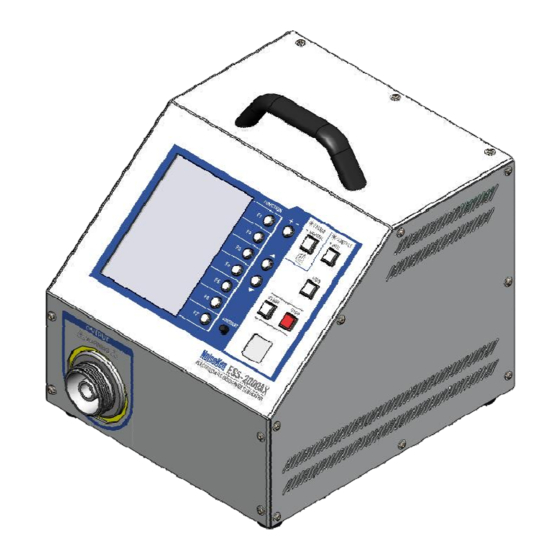
8. NAME AND FUNCTION OF EACH PART 8-1. Main Unit (Front Panel) Figure 8-1 Main Unit (Front Panel) [1] Model name The product name and model name of the instrument and the company logo. [2] High-voltage output connector Connector with a maximum output voltage of 30.5kV. The discharge gun connects to this connector. -
Page 19: Main Unit (Rear Panel)
8. NAME AND FUNCTION OF EACH PART 8-2. Main Unit (Rear Panel) [10] [11] [13] [12] Figure 8-2 Main Unit (Rear Panel) [6] AUX connector A D-SUB 15-pin connector. Used to connect to external devices. See Chapter 13-1 for details. [7] Optical communications connector The instrument can communicate with a PC via optical fiber. -
Page 20: Discharge Gun
8. NAME AND FUNCTION OF EACH PART [11] Serial number label Contains the model name, serial number, and other information. [12] Inspection certification Label certifying that the instrument passed the Noise Laboratory delivery inspection. [13] User warning Noise Laboratory Co., Ltd. accepts no liability for damages resulting from incorrect operation. -
Page 21: Operation Panel
8. NAME AND FUNCTION OF EACH PART 8-4. Operation Panel Figure 8-4 Operation Panel LCD display Displays status information. + + + + - - - - + + + + - - - - Output polarity selection switch Selects the polarity of the applied voltage. Up/down switches Adjusts the selected value up or down. - Page 22 8. NAME AND FUNCTION OF EACH PART CONTACT/AIR CONTACT/AIR Static discharge mode selection switch Selects either contact discharge mode (CONTACT) or air discharge mode (AIR). TRIG TRIG TRIG switch Used to fire the trigger from the main unit. START START START switch START START...
-
Page 23: Radiation Level Mode Function
9. RADIATION LEVEL MODE FUNCTION To improve the reliability of its electrostatic discharge simulators, Noise Laboratory released the new TC-815R discharge gun in 2004. The new discharge gun was an upgrade of the TC-815P model and featured reduced ringing in the output current waveform and lower radiated noise from the discharge gun. -
Page 24: How To Use The Radiation Level Modes
9. RADIATION LEVEL MODE FUNCTION [2] Different voltage waveform With IEC 61000-4-2 and ISO 10605 standards, there is the difference in the voltage waveform which does not have stipulation. Conditions under which differences in waveform appear. Electrostatic discharge mode: Contact discharge The electrostatic discharge is applied to a point at which the impedance between the discharge tip and discharge gun GND is 2MΩ... -
Page 25: How To Select Extra Mode (Extra)
9. RADIATION LEVEL MODE FUNCTION 9-4. How to Select Extra Mode (EXTRA) If the radiation level mode selection switch is held down when the POWER switch is turned on, the simulator starts up in extra mode (EXTRA). The radiation level mode selection cannot be changed while the simulator is running (except when utility mode is used to specify settings). -
Page 26: Connections
CONNECTIONS Turn the power switch to "Off" on the instrument before connecting or changing any of the cables Failure to comply with this rule may result in electric shock, injury, or misoperation. Do not insert objects into the instrument and its connectors Inserting metallic or flammable items into the ventilation slits, connectors, or other openings may result in fire, electric shock, or similar. -
Page 27: Connecting The Ac Power Cable
10. CONNECTIONS 10-2. Connecting the AC Power Cable Plug the AC power cable into a socket that has a protective earth terminal The AC power cable provided with the instrument has a three-pin plug that connects to the power supply and protective earth terminal. The protective earth on the three-pin plug connects via the AC power cable to the metal parts on the instrument. - Page 28 10. CONNECTIONS An AC power cable with a three-pin plug is provided with the simulator to connect to the mains power supply and protective earth. The protective earth on the three-pin plug connects via the AC power cable to the metal parts on the simulator.
-
Page 29: Operation
OPERATION 11-1. Turning the Power On or Off Press the "|" side of the power switch on the rear of the simulator to turn on the power. This lights up the operation panel display. Press the "O" side of the power switch to turn off the power and the operation panel display. - Page 30 11. OPERATION Sequence mode [SEQUENCE] Changes to sequence mode. ⇒ See Chapter 11-5. Sequence mode works by performing a series of operations by combining units created in manual test mode. You can create up to 20 programs. Trigger selection [TRIGGER] The available trigger input methods are GUN, ESS, and EXTERNAL.
-
Page 31: Iec Standard Test Mode
11. OPERATION 11-3. IEC Standard Test Mode This automatically sets the output voltages to the severity levels specified in the IEC standard. Figure 11-4 IEC Mode Setting Electrostatic Discharge Mode Selection Pressing the electrostatic discharge mode selection switch toggles CONTACT/AIR CONTACT/AIR between contact discharge mode [CONTACT] and air discharge mode [AIR]. - Page 32 11. OPERATION Test Level Settings Pressing the switch enables the test level to be selected using the switches. The test level can also be selected by holding down the switch. Table 11-1 IEC Test Levels lists the output voltage settings. Table 11-1 IEC Test Levels Output Voltage (kV) Contact...
- Page 33 11. OPERATION Starting a Test Warning - Before you start, check that the discharge gun is connected. - Starting a test will generate the indicated voltage in the high-voltage output connector and discharge gun. Take adequate precautions. - Take care to ensure there are no other people close to the discharge gun, and that all necessary preparation for the discharge test has been carried out.
-
Page 34: Manual Test Mode
11. OPERATION 11-4. Manual Test Mode Manual test mode is used to perform tests in which all of the settings are specified by the user. Manually specified test conditions can be stored in units numbered 1 to 99. Saving the settings to units 1 to 99 is performed automatically. The unit numbers are used to setup tests in sequence test mode. - Page 35 11. OPERATION Setting Unit Selection Use the switch to select the unit in which to save the settings. By changing the unit number, you can save different settings in each unit. The unit numbers are also used in sequence mode. Test Voltage Setting Pressing the switch enables...
- Page 36 11. OPERATION When polarity = + or - When ± specified Start Start Output voltage Output voltage Start voltage Start voltage Perform for specified Perform for specified number of times for number of times for specified polarity + polarity Wait for Wait for Wait for trigger...
- Page 37 11. OPERATION Starting a Test Warning - Before you start, check that the discharge gun is connected. - Starting a test will generate the indicated voltage in the high-voltage output connector and discharge gun. Take adequate precautions. - Take care to ensure there are no other people close to the discharge gun, and that all necessary preparation for the discharge test has been carried out.
- Page 38 11. OPERATION Stopping a Test Warning As the simulator waits for the next trigger input after the specified number of discharges have been performed, the high-voltage power supply in the simulator does not turn off. Always press the STOP switch to end the test. STOP Pressing the switch stops the test, turns off the internal high-voltage power...
-
Page 39: Sequence Mode
11. OPERATION 11-5. Sequence Mode Sequence mode works by performing a series of operations which consist of a combination of units created in manual test mode. You can define up to 20 programs in sequence mode by switching between pages. Each sequence can consist of a combination of units up to 30 steps. - Page 40 11. OPERATION [5] Adding a unit Press the switch to insert the displayed unit at the specified location in the sequence. Any units after the insertion position are shifted downwards. [6] Deleting a unit Press the switch to delete the unit at the specified location in the sequence. Any units after the deletion position are shifted upwards.
- Page 41 11. OPERATION Starting a Test Warning - Before you start, check that the discharge gun is connected. - Starting a test will generate the indicated voltage in the high-voltage output connector and discharge gun. Take adequate precautions. - Take care to ensure there are no other people close to the discharge gun, and that all necessary preparation for the discharge test has been carried out.
- Page 42 11. OPERATION Stopping a Test Warning As the simulator waits for the next trigger input after the specified number of discharges have been performed, the high-voltage power supply in the simulator does not turn off. Always press the STOP switch to end the test. STOP Pressing the switch stops the test, turns off the internal high-voltage power...
-
Page 43: Utility Mode
11. OPERATION 11-6. Utility Mode 図 図 図 図 11-15 ユーティリティモード画面 ユーティリティモード画面 ユーティリティモード画面 ユーティリティモード画面 1 Figure 11-14 Utility Mode Screen 1 Figure 11-13 Utility Mode Screen 2 Switch between setting screens [Next Page/Pre.PAGE] This switches the utility mode setting screen between screen 1 and screen 2 shown above. - Page 44 11. OPERATION Every Discharge : Performs neutralization after each discharge operation. However, this setting defaults to the "Count Up" operation if the discharge interval is less than 1 second. Count Up : Performs neutralization after the number of discharges specified by the Count setting have been performed.
- Page 45 11. OPERATION Turn off high-voltage output if idle [Auto Stop] This specifies the time after which the high voltage is turned off if the high voltage is left on but no operation is performed. Use the switches to set the time. 0...
-
Page 46: Background Knowledge About Electrostatic Testing
BACKGROUND KNOWLEDGE ABOUT ELECTROSTATIC TESTING Principle of electrostatic tester The basic circuit of an electrostatic is shown below. The high voltage generated in the high voltage power supply is charged in the charging capacitor through the charging relay and charging resistance. When the charging relay is turned off and the discharging relay is turned on, the high voltage (electric charge) accumulated in the charging capacitor is applied to EUT through the discharging resistance. - Page 47 12. BACKGROUND KNOWLEDGE ABOUT ELECTROSTATIC TESTING Contact Discharge and Air Discharge The electrostatic discharge can be applied either by direct contact (CONTACT) or via the air (AIR). The test procedure and electrostatic simulator operation are different in each case, as described below. The effect on the EUT is also different. Contact discharge (CONTACT) The electrostatic discharge is applied by placing the discharge tip in direct contact with the case of the EUT (if the case is painted, the paint is peeled off to...
-
Page 48: Auxiliary Interface
AUXILIARY INTERFACE 13-1. AUX Connector This is a DSUB15 female connector used for the warning light (Model: 11-00014A), automatic elimination probe (Model: 01-00013A), and control signal input and output. If using both the warning light and automatic elimination probe (both of which are available as options), please use the AUX connector junction box (Model: 05-00052A). -
Page 49: Optical Communication Connector
13. AUXILIARY INTERFACE External trigger input The external trigger can be used to input the trigger from an external source. To use this function, select [EXTERNAL] in the trigger selection setting in the initial menu screen. ⇒ See 11-2. To input an external trigger, input a high level (5V to 24V) with a pulse time of 100ms or longer. -
Page 50: Error Display
ERROR DISPLAY Table 14-1 Error List ERROR 1 Gun interlock error Description of error An interlock is present. How to clear error Push the STOP switch. How to prevent Attach the high-voltage input connector of the discharge gun error correctly. ERROR 2 External interlock error Description of... -
Page 51: Specifications
SPECIFICATIONS Simulator (ESS-2000AX) Function/Performance Parameters Output polarity Positive or negative 0.20kV to 30.0kV (30.5kVmax) Output voltage 0.20kV to 10.0kV: 0.01V step setting 10.0kV to 30.0kV: 0.1V step setting 0.20kV to 1.9kV ±10% Tolerance 2.0kV to 30.0kV ±5% Normal mode: 0.05s to 600.0s ±10% Repeat cycle Extra mode: 1.00s to 600.0s ±10%... -
Page 52: Warranty
WARRANTY Servicing terms The following terms are applicable to servicing by Noise Laboratory Co., Ltd., (hereafter referred to as the Company) provided to maintain the intended performance of its products. Scope The following terms shall apply only to products made by the Company. Technical servicing fee In the event of a failure of a product within the warranty period (see warranty section), the Company will repair a product without charge. - Page 53 16. WARRANTY Limited Warranty Noise Laboratory Co., Ltd. (hereafter referred to as the Company) warrants its products to be free from defects in materials and workmanship under normal use and service for a period of one year from date of delivery. In the event of failure of a product covered by this warranty, the Company will repair the product or may, at its option, replace it in lieu of repair without charge.
-
Page 54: Maintenance
MAINTENANCE When repair, maintenance or internal adjustment of the unit is required, a qualified service engineer takes charge of such work. Maintenance on the user side is restricted to the outside cleaning and functional check of the unit. When checking or replacing the fuse, turn off the switch of the unit and disconnect the plug socket beforehand. -
Page 55: Contacting Technical Support
18. CONTACTING TECHNICAL SUPPORT CONTACTING TECHNICAL SUPPORT If you experience a malfunction, please have available both the model and serial number of your unit and contact the nearest distributor/agent or Noise Laboratory Technical Support. When it is necessary to send your unit back to Noise Laboratory, fill in the repair order form completely, pack the unit in the original package or equivalent one suitable for transit, and send the package. - Page 56 NOISE LABORATORY CO., LTD. Produced by: Noise Laboratory Co., Ltd. 1-4-4, Chiyoda, Chuo-ku, Sagamihara City, Kanagawa Pref., 252-0237, Japan TEL: +81-(0)42-712-2051 FAX: +81-(0)42-712-2050 URL: http://www.noiseken.co.jp Printed in Japan...
Need help?
Do you have a question about the ESS-2000AX and is the answer not in the manual?
Questions and answers