Table of Contents
Advertisement
Quick Links
BAS6960
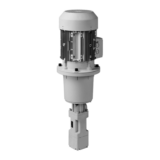
BRINKMANN-Screw Pump
BFS / TFS / FFS
BRINKMANN PUMPS, Inc.
47060 Cartier Drive
Wixom, MI 48393
USA
Phone: +1 248 926 9400
Fax.:
+1 248 926 9405
Subject to change without prior notice.
Brinkmann Pumpen
Operating Instructions
Edition 03/2014
www.BrinkmannPumps.com
contact @BrinkmannPumps.de
Order - No.: BAS6960 ENGLISH
Page 1 of 12
Advertisement
Table of Contents

Related Manuals for BRINKMANN PUMPS BFS


Summary of Contents for BRINKMANN PUMPS BFS
- Page 1 BAS6960 Operating Instructions BRINKMANN-Screw Pump BFS / TFS / FFS BRINKMANN PUMPS, Inc. 47060 Cartier Drive Wixom, MI 48393 Phone: +1 248 926 9400 www.BrinkmannPumps.com Fax.: +1 248 926 9405 contact @BrinkmannPumps.de Subject to change without prior notice. Order - No.: BAS6960 ENGLISH ...
-
Page 2: Table Of Contents
BRINKMANN-Screw Pump Type BFS / TFS / FFS Contents Indication to the manual ........2 8 Servicing and Maintenance ....... 8 Description of product and working principle .. 2-3 9 Trouble shooter’s guide ........9 Safety instructions .......... 4-5 10 Spare part ............10 Transport and storage ........ - Page 3 The manufacturer is not responsible for Max. delivery 2175 PSI (150 bar) (2900 PSI (200 any damages resulting from use of the pumps in such pressure bar ) for BFS/FFS1, BFS/FFS2 and applications. TFS/BFS/FFS3 upon request) Minimum Ensure that the discharge pressure...
-
Page 4: Safety Instructions
3 Safety instructions Safety instructions relevant for operation When operating the pump, the safety instructions If hot or cold machine components involve haz- contained in this manual, the relevant national acci- ards, they must be guarded against acciden-tal dent prevention regulations and any other service contact. -
Page 5: Transport And Storage
Unauthorized alterations and production of spare parts Any modification may be made to the machine only after consultation with the manufacturer. Using spare parts and accessories authorized by the manufactur- er is in the interest of safety. Use of other parts may exempt the manufacturer from any liability. - Page 6 In the case of a G4 execution, the leakage connec- tion must be piped without back pressure (see draw- ing 2) and routed back into the tank in a non- pressurised state. The connection MUST never be closed or valved off. Pressure relief valves (DBV’s) G4 execution...
-
Page 7: Start Up / Shut Down
6 Start up / Shut down The motor is surface-cooled and compliant with DIN IEC 34 and EN 60034 (protection degree IP 55). Start up / Turn motor on According to the European Standard EN809 a motor Open all valves in discharge line completely and overload must be installed and properly set to the full de-energize pressure relief valve (start up pump load amps stated on the pump name plate. -
Page 8: Operation
7 Operation Operation with a pressure relief valve Liquid level Check for proper liquid level. When operating with a pressure relief valve the The minimum liquid level (H, see drawing 1) user should bear in mind that the self-setting op- should be 2.75 Inch (70 mm) for BFS1, BFS2, and erating pressure depends on the flow rate, espe- TFS3, 3.94 Inch (100 mm) for TFS4 and TFS5... -
Page 9: Trouble Shooter's Guide
9 Trouble shooter’s guide Fault Possible causes Remedy Pump does not pump Incorrect direction of rotation of pump Reverse direction of rotation of motor. Pump is operating without fluid Add pumping fluid; raise fluid level in tank. Shut-off valves are closed Open valves All fluid is pumped through a bypass Check bypass lines and relief valve settings. -
Page 10: Spare Part
10 Spare part 10.1 Pump design Item Description Motor Screw pump Bell housing Motor coupling hub Coupling spider Pump coupling hub Set screw 10.2 Indications to the spare part order Spare parts are available from the supplier. Standard commercially available parts are to be purchased in accordance with the model type. -
Page 11: Disposal
Dimensions for BFS1/BFS2 (2 pole motors): In each case the distance is measured by the inner surface of the coupling hub to the shaft end Inner surface of the coupling hub Dimensions for TFS3, TFS4 and TFS5 (2 pole motors): TFS3 TFS4 TFS5... -
Page 12: Warranty
13 WARRANTY Brinkmann Pumps, Inc. warrants that the product contained herein conforms to the descrip- tion in Brinkmann's catalog and that if this product shall fail to conform to the description thereof or to any express or implied warranty, Brinkmann shall, upon written notice of such nonconformity within one year of the date of its shipment from BRINKMANN'S plant, repair or replace such non-conforming material at the original point of delivery.
Need help?
Do you have a question about the BFS and is the answer not in the manual?
Questions and answers