Table of Contents
Advertisement
Quick Links
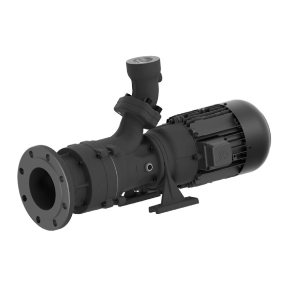
BRINKMANN-Horizontal End Suction Pumps
SBC820...1120
Brinkmann Pumpen
K. H. Brinkmann GmbH & Co. KG
Friedrichstraße 2
D-58791 Werdohl
Tel.: +49-2392 / 5006-0
Fax.: +49-2392 / 5006-180
Subject to change without prior notice.
© Brinkmann Pumpen
BE8082 Operating Instructions
(Translation of original)
Edition
www.brinkmannpumps.de
sales@brinkmannpumps.de
Order - No.: BE8082 ENGLISH
01/2023
1
Advertisement
Table of Contents

Related Manuals for BRINKMANN PUMPS BE8082


Summary of Contents for BRINKMANN PUMPS BE8082
- Page 1 SBC820...1120 Brinkmann Pumpen K. H. Brinkmann GmbH & Co. KG Friedrichstraße 2 D-58791 Werdohl Tel.: +49-2392 / 5006-0 www.brinkmannpumps.de Fax.: +49-2392 / 5006-180 sales@brinkmannpumps.de Subject to change without prior notice. Order - No.: BE8082 ENGLISH © Brinkmann Pumpen 01/2023 Edition...
-
Page 2: Table Of Contents
– Pay attention of the limit of application in table 1! The cutter pumps are intended for installation in machines and cannot be operated alone. BE8082 01/2023 Edition... - Page 3 4.0 / 4.55 SBC820 1000 5.5 / 6.3 SBC1120 1100 Pipe connection: Suction side DN125/PN16, Pressure side G 2. The motor is surface-cooled and compliant with DIN IEC 34 and EN 60034 (protection degree IP 55). BE8082 01/2023 Edition...
-
Page 4: Safety Instructions
• arrow indicating the direction of rota- tor is to make sure that the contents of the op- erating manual are fully understood by the tion personnel. • symbols indicating fluid connections be observed and kept legible. BE8082 01/2023 Edition... -
Page 5: Transport And Storage
Risk of clamping or crushing body parts lel alignment to the pump axis. when installing or removing the pump ex- ists! – Pump must be secured with appropriate hoist. BE8082 01/2023 Edition... - Page 6 The electrical wiring must be performed ac- – In order to avoid the formation of an igni- cording to the wiring diagram shown inside tion spark, no foreign particles may enter the terminal box cover. the tank. (Please see above sample wiring diagrams) BE8082 01/2023 Edition...
-
Page 7: Start Up / Shut Down
Reassure that pump is disconnected from power source and cannot be switched on. – Verify that there is no voltage at the termi- nal board! – Open terminal box and disconnect the power leads. – Empty out the pump. BE8082 01/2023 Edition... -
Page 8: Servicing And Maintenance
GLRD stamped in on the switched off! motor side of the pump foot and must include an oil receiver with a capacity of 0.45 litres. Check this through the inspection window. Oil receiver Castrol WHITEMOR WOM14 or equivalent oil. BE8082 01/2023 Edition... -
Page 9: Trouble Shooter's Guide
Replace pump mechanism Incorrect flow or pressure Wrong power supply (voltage or Power supply must correspond cycles) with name plate rating Running noise/Vibration Foreign objects in pump end Remove foreign objects Impeller damaged Replace impeller Bearing/Bushing broken Replace bearing/bushing BE8082 01/2023 Edition... -
Page 10: Spare Part
DIN 908 94 Spring washer DIN 7980 28 Sealing ring DIN 7603 95 O-ring 29 O-ring 96 Screw plug DIN 908 30 Shaft seal 97 Sealing ring DIN 7603 31 Socket head cap screw with lock DIN 912 BE8082 01/2023 Edition... -
Page 11: Repair Instructions / Replacing The Rotary Mechanical Seal / The Shaft Clamp
– Use two screwdrivers to push the impeller (75) from the insert shaft (91). Insert the screwdrivers between the impeller (75) and the pump body (50). Drawing 5 – Remove the woodruff key (53) from the insert shaft (91). Loosen the socket head cap BE8082 01/2023 Edition... - Page 12 Do not, under any circumstances, re- move the screws on the shaft clamp (1) completely. – Loosen the screws on the shaft clamp (1). – Remove the insert shaft (2) and shaft clamp (1) off the motor shaft (3). BE8082 01/2023 Edition...
-
Page 13: Disposal
When disposing of the pump or the packaging materials the local and national regulation for proper disposal must be complied with. – Prior to its disposal, the pump must be com- pletely drained and decontaminated if neces- sary. BE8082 01/2023 Edition... -
Page 14: Eclarations Of Conformity
Manufacturer Brinkmann Pumpen, K. H. Brinkmann GmbH & Co. KG Friedrichstraße 2 D-58791 Werdohl Germany This declaration of conformity is issued under the sole responsibility of Brinkmann Pumps and belongs to the following product. Product name Horizontal End-Suction Pumps Type SBC820…1120... - Page 15 Dr. H. Abou Dayé K. H. Brinkmann GmbH & Co. KG Friedrichstraße 2, D-58791 Werdohl ..............Dokumentationsbevollmächtigter / Representative of Dr.-Ing. Dirk Wenderott documentation/ Mandataire de documentation / Chief Product Officer (CPO) Mandatario de documentación Head of Engineering BE8082 01/2023 Edition...
Need help?
Do you have a question about the BE8082 and is the answer not in the manual?
Questions and answers