
Related Manuals for Weidmüller u-control UC20-WL2000-AC-CAN


Summary of Contents for Weidmüller u-control UC20-WL2000-AC-CAN
- Page 1 Controllers u-control UC20 Manual (Original) UC20-WL2000-AC-CAN 2928020000 UC20-WL2000-AC 1334950000 UC20-WL2000-IOT 1334990000...
-
Page 2: Table Of Contents
Content About this documentation Earthing and shielding Symbols and notes Earthing of shielded cables Complete documentation Potential ratios Hardware and software versions described Electromagnetic compatibility (EMC) Shielding of cables Safety General safety notice Commissioning using u-create web Intended use Requirements Use in a potentially explosive atmosphere Starting u-create web Legal notice... -
Page 3: About This Documentation
1 About this documentation | Symbols and notes About this documentation Symbols and notes The situation-dependent safety notices may contain the fol- lowing warning symbols: The safety notices in this documentation are designed Symbol Meaning according to the severity of the danger. Warning against hazardous electrical DANGER voltage Imminent risk to life! -
Page 4: Hardware And Software Versions Described
Hardware and software versions described The present manual describes the following hardware and software versions of the controllers: Hardware Software Order No. Controller version version u-create web 1334950000 UC20-WL2000-AC 01.23.00 1.15.1 u-OS 2.0.0 2928020000 UC20-WL2000-AC-CAN 01.00.00 u-OS 2.1.0 u-create web 1334990000 UC20-WL2000-IOT 01.23.00... -
Page 5: Safety
2 Safety | General safety notice Safety This section includes general safety instructions for handling cal operations rooms. Only trained and authorised personnel the u-control system. Specific warning notices for specific may access the equipment. tasks and situations are given at the appropriate places in For applications requiring functional safety, the surrounding the documentation. -
Page 6: Intended Use
2 Safety | Intended use Intended use and on power-feed modules) must be specified for at least 90 °C. – If the temperature under rated conditions exceeds 70 °C The products of the UC20 series are intended for use in in- at the cable or conduit entry point, or 80 °C at the dustrial automation. -
Page 7: Legal Notice
2 Safety | Legal notice Legal notice The u-control series products are CE-compliant in accor- dance with Directive 2014/30/EU (EMC Directive) and Directive 2014/35/EU (Low Voltage Directive). They also meet the requirements of the ATEX Directive 2014/34/EU unless otherwise noted. The results of the measurements according to CISPR 16-2-3 should also be suitable to demonstrate the compliance of the u-control devices to the limits for radiated emissions as defined by CFR 47 Part 15, Subpart B, §15.109, Class A... -
Page 8: System Overview
3 System overview System overview Example arrangement of a u-control station Height (H) Width (W) Depth (D) The products of the u-control series are programmable logic controllers. The UC20-WL2000 controllers are configured, parameterised and programmed using the integrated engi- Controller 120.0 / 4.72 52.0 / 2.05 76.0 / 2.99 neering tool u-create web via a web browser. - Page 9 3 System overview Power supply concept The u-control controllers and the u-remote modules use three internal current paths as described in following chapter 4. In- put and output paths are supplied seperately, therefore a cus- tom-fit refreshing by power-feed modules is easyly feasible. The figure shows the general supply concept.
-
Page 10: General Description Of The Controller
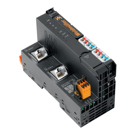
3 System overview | General description of the controller General description of the controller Controller (example: UC20-SL2000-EC-CAN) Release lever for the DIN rail fixing Connector frame unlocking device Data line connection (RJ45) LED power supply controller CAN interface (only UC20-WL2000-AC-CAN) Controller status LEDs Seats for module markers 10 Power supply connector for the system and input modules 11 Power supply connector for output modules... -
Page 11: Approvals And Standards
3 System overview | Approvals and standards Approvals and standards cULus UL 61010-2-201 UL 121201, 9th Edition, Issue Date 2017/09/15 CSA C22.2 NO. 213, 3rd Edition, Issue Date 2017/09/15 Maritime und offshore applications see chapter 4 Explosion protection ATEX: IEC/EN 60079-0:2018, IEC/EN 60079-7:2015+A1:2018 IECEx: IEC 60079-0, 7th Edition (2017-12) + Corr. -
Page 12: Connector Pg 1.5 Mm
3 System overview | Connector PG 1.5 mm Connector PG 1.5 mm Mechanical fixing elements A connector frame can take up to four connectors, and four The station is fixed in the installation position by an end conductors can be connected to each connector. “PUSH IN” bracket at either side. The last I/O module is protected technology allows for fine-wired conductors with crimped against dust by a cover plate. -
Page 13: Type Plate
3 System overview | Type plate Type plate Battery Each controller features a type plate, which includes iden- The controller can be equipped with a battery (for specifica- tification information and the key technical specifications. tion see technical data). The battery continues to supply the In addition, a QR code allows for direct online access to the integrated real-time clock if the power supply is interrupted. -
Page 14: Configuration
4 Configuration | Connectable u-remote I/O modules Configuration Connectable u-remote I/O modules Orientation of the station The release notes concerning the controllers The u-control station is usually installed on a horizontally describe which u-remote modules at which firm- positioned DIN rail. ware version are supported. -
Page 15: Installation Distances
4 Configuration | Installation distances Installation distances 20 mm 0.97" In order to be able to carry out the installation and subse- quent maintenance work and to ensure sufficient ventilation, the u-control station must be installed while observing the following minimum distances (see the following figures). ATTENTION 35 mm 40 mm... -
Page 16: Use In A Potentially Explosive Atmosphere
4 Configuration | Use in a potentially explosive atmosphere Use in a potentially explosive atmosphere For vertical installation please interchange height and width. When calculating the width, 12.5 mm / 0.49" must be added for the end bracket MEW 35/1 (Order No. Please regard the safety notes in section 2.3. 1805610000). -
Page 17: Use In Maritime And Offshore Applications
4 Configuration | Use in maritime and offshore applications Use in maritime and offshore applications “PUSH IN” system cabling The UC20 products described in this manual comply with Controllers are equipped with the “PUSH IN” connector system. the requirements of the classification society DNV. These Single-strand and fine-strand lines with wire-end ferrules can products are approved for the usage in maritime and off- be inserted without the need for a tool. -
Page 18: Current Demand And Power Supply
4 Configuration | Current demand and power supply Current demand and power supply ATTENTION Equipment may become damaged if improperly rat- The u-control controllers use three internal current paths: ed circuit protection is used! ▶ In order to achieve spezification according to UL 248-14 The I system current path supplies the communication use a UL-approved Type-B automatic circuit breaker... -
Page 19: Example Calculation For The Power Supply
4 Configuration | Example calculation for the power supply Example calculation for the power supply Calculation of current demand for the output current The current consumption of each module and the current The power supply must be calculated individually for each demand of the connected actuators must be considered for station installation. - Page 20 4 Configuration | Example calculation for the power supply Example calculation for the current demand (all current values in A) Module Product Simultaneity Cumulative Cumulative Cumulative cur- factor current demand current demand rent demand of of the input cur- of the controller the PF-O output rent path output power...
-
Page 21: Calculation Of Power Loss
4.10 Calculation of power loss 4.11 Feedback energy in DO modules The power loss of the controller is calculated as follows: With digital output modules, power is fed back through the channels when inductive loads are switched off. The respec- + N ... -
Page 22: Detail Description Of Controllers
5 Detail description of controllers | UC20-WL2000-AC Detail description of controllers UC20-WL2000-AC Status indicators Up to 64 active u-remote modules can be connected via the u-remote system bus to the UC20-WL2000-AC controller. The controller has two Ethernet connections for integration WL-AC into the existing network architecture or HMI connections. The integrated engineering tool u-create web can be launched via the USB service interface or over Ethernet. - Page 23 5 Detail description of controllers | UC20-WL2000-AC Controller power supply LED Green: supply voltage > 18 V Red: at least one current path < 18 V WL-AC TD+ 1 TD– 2 RD+ 3 RD– 6 RUN/STOP TD+ 1 L/A X1 TD– 2 L/A X2 RD+ 3 24 V DC IN RD– 6 24 V DC IN GND IN 3.1 Green: input current path supply voltage > 18 V DC GND IN 3.2 Red: input current path supply voltage < 18 V DC...
- Page 24 5 Detail description of controllers | UC20-WL2000-AC Internal from the control card System System System µC card Battery RJ45 24 V/5 A Output RJ45 UC20-WL2000-AC Block diagram UC20-WL2000-AC Manual u-control 2604080000/08/08.2023...
- Page 25 5 Detail description of controllers | UC20-WL2000-AC Technical data UC20-WL2000-AC (Order No. 1334950000) General data Type of connection "PUSH IN" solid, fine-wired Wire cross-section 0.14 ... 1.5 mm (AWG 16 – 26) Configuration interface Micro USB 2.0 Degree of protection (IEC 60529) IP20 Flammability rating UL 94 System data Connection 2 x RJ-45 Number of modules max.
- Page 26 5 Detail description of controllers | UC20-WL2000-AC Technical data UC20-WL2000-AC (Order No. 1334950000) Tests Vibration resistance 5 Hz ≤ f ≤ 8.4 Hz: 3.5 mm amplitude as per IEC 60068-2-6 8.4 Hz ≤ f ≤ 150 Hz: 1 g acceleration as per IEC 60068-2-6 Shock resistance 15g over 11ms, half sine wave, as per IEC 60068-2-27 Potential isolation Test voltage max. 28.8 V inside a channel 500 V DC field/system (according to EN 60079- 15:2010) Pollution degree 2 (according to DIN EN 60664-1:2008) Overvoltage category II (according to DIN EN 50178) Currently u-create web does not support retain variables but variables in the data storage.
-
Page 27: Uc20-Wl2000-Ac-Can
5 Detail description of controllers | UC20-WL2000-AC-CAN UC20-WL2000-AC-CAN Status indicators Up to 64 active u-remote modules can be connected via the u-remote system bus to the UC20-WL2000-AC-CAN controller. The controller has two Ethernet connections for WL-AC-CAN integration into the existing network architecture or HMI con- nections. - Page 28 5 Detail description of controllers | UC20-WL2000-AC-CAN Controller power supply LED Green: supply voltage > 18 V WL-AC-CAN Red: at least one current path < 18 V WL-AC-CAN TD+ 1 TD– 2 RD+ 3 RD– 6 TD+ 1 L/A X1 TD– 2 L/A X2 RD+ 3 24 VDC IN RD– 6 24V DC IN GND IN 3.1 Green: input current path supply voltage > 18 V DC GND IN 3.2 Red: input current path supply voltage < 18 V DC 24V DC OUT...
- Page 29 5 Detail description of controllers | UC20-WL2000-AC-CAN Internal from the control card System System System µC card Battery RJ45 RJ45 24 V/5 A Output UC20-WL2000-AC-CAN Block diagram UC20-WL2000-AC-CAN 2604080000/08/08.2023 Manual u-control...
- Page 30 5 Detail description of controllers | UC20-WL2000-AC-CAN Technical data UC20-WL2000-AC-CAN (Order No. 2928020000) General data Type of connection "PUSH IN" solid, fine-wired Wire cross-section 0.14 ... 1.5 mm (AWG 16 – 26) Configuration interface Micro USB 2.0 Degree of protection (IEC 60529) IP20 Flammability rating UL 94 System data Connection 2 x RJ-45, 1 x CAN interface Number of modules max.
- Page 31 5 Detail description of controllers | UC20-WL2000-AC-CAN Technical data UC20-WL2000-AC-CAN (Order No. 2928020000) Tests Vibration resistance 5 Hz ≤ f ≤ 8.4 Hz: 3.5 mm amplitude as per IEC 60068-2-6 8.4 Hz ≤ f ≤ 150 Hz: 1 g acceleration as per IEC 60068-2-6 Shock resistance 15g over 11ms, half sine wave, as per IEC 60068-2-27 Potential isolation Test voltage max. 28.8 V inside a channel 500 V DC field/system (according to EN 60079- 15:2010) Pollution degree 2 (according to DIN EN 60664-1:2008) Overvoltage category II (according to DIN EN 50178) 2604080000/08/08.2023 Manual u-control...
-
Page 32: Uc20-Wl2000-Iot
5 Detail description of controllers | UC20-WL2000-IOT UC20-WL2000-IOT Status indicators Up to 64 active u-remote modules can be connected via the u-remote system bus to the UC20-WL2000-IOT controller. The controller has two Ethernet connections for integration into the existing network architecture or HMI connections. The integrated engineering tool u-create web can be launched via the USB service interface or over Ethernet. - Page 33 5 Detail description of controllers | UC20-WL2000-IOT Controller power supply LED Green: supply voltage > 18 V Red: at least one current path < 18 V TD+ 1 TD– 2 RD+ 3 RD– 6 RUN/STOP TD+ 1 L/A X1 TD– 2 L/A X2 RD+ 3 24 V DC IN RD– 6 24 V DC IN GND IN 3.1 Green: input current path supply voltage > 18 V DC GND IN 3.2 Red: input current path supply voltage < 18 V DC...
- Page 34 5 Detail description of controllers | UC20-WL2000-IOT Internal from the control card System System System µC card Battery RJ45 24 V/5 A Output RJ45 UC20-WL2000-AC Block diagram UC20-WL2000-IOT Manual u-control 2604080000/08/08.2023...
- Page 35 5 Detail description of controllers | UC20-WL2000-IOT Technical data UC20-WL2000-IOT (Order No. 1334990000) General data Type of connection "PUSH IN" solid, fine-wired Wire cross-section 0.14 ... 1.5 mm2 (AWG 16 – 26) Configuration interface Micro USB 2.0 Degree of protection (IEC 60529) IP20 Flammability rating UL 94 System data Connection 2 x RJ-45 Number of modules max. 64 active Processor Dual Core ARM A9, 624 MHz Memory...
- Page 36 5 Detail description of controllers | UC20-WL2000-IOT Technical data UC20-WL2000-IOT (Order No. 1334990000) Tests Vibration resistance 5 Hz ≤ f ≤ 8.4 Hz: 3.5 mm amplitude as per IEC 60068-2-6 8.4 Hz ≤ f ≤ 150 Hz: 1 g acceleration as per IEC 60068-2-6 Shock resistance 15g over 11ms, half sine wave, as per IEC 60068-2-27 Potential isolation Test voltage max. 28.8 V inside a channel 500 V DC field/system (according to EN 60079- 15:2010) Pollution degree 2 (according to DIN EN 60664-1:2008) Overvoltage category II (according to DIN EN 50178) Currently u-create web does not support retain variables but variables in the data storage.
-
Page 37: Installation
6 Installation | Preparations for assembly Installation Stripping lengths WARNING The required stripping length for every Weidmüller product Explosion risk! is specified in mm. These lengths, e.g. 6 mm ± 0.5 mm, During assembly work, sparks can form and ≥ 10 mm ±1 mm, must be observed. This also applies to surfaces may become excessively hot. - Page 38 6 Installation | Preparations for assembly In the case of vertical mounting, the controller must always Use in a potentially explosive atmosphere be arranged as the first module at the bottom and secured Please regard the safety notes in section 2.3. with a reinforced end bracket for vertical mounting (Order no.
- Page 39 6 Installation | Preparations for assembly For vertical installation interchange height and width. When calculating the width, 4.5 mm for the must be added for the end bracket MEW 35/1 (Order No. 1805610000). 20 mm 0.97" Installation sequence A u-control station may only be installed in this sequence (starting from the left/bottom): –...
-
Page 40: Assembling The U-Control Station
6 Installation | Assembling the u-control station Assembling the u-control station WARNING Explosion risk! ▶ Prior to starting work, make sure that there is not a potentially explosive atmos- phere! WARNING Dangerous contact voltage! ▶ All work on the u-control station must be Attaching the end bracket carried out with the power supply discon- When installing u-control products and u-remote... - Page 41 6 Installation | Assembling the u-control station ▶ Place the controller (module side to the right) on the DIN rail so that it audibly clicks into place. Sliding the module into position ▶ Attach all of the other modules as described above. Attaching the controller to the DIN rail ▶...
-
Page 42: Wiring
6 Installation | Wiring Wiring Wiring of modules with connectors PG 1.5 mm Only copper wires with a cross section between 0.14 mm² and 1.5 mm² (AWG 16 – 26) may be connected. WARNING Explosion risk! We recommend using the following wire-end ferrules: ▶ Before assembly, make sure that there is Cross-section Weidmüller order no. -
Page 43: Inserting The Battery
6 Installation | Inserting the battery Inserting the battery WARNUNG Explosion risk! ▶ Do not use the controller with a battery in a potentially explosive atmosphere. WARNING Inserting the battery Battery may explode if mistreated! Use of a wrong battery type may cause ▶... -
Page 44: Inserting The Microsd Card
6 Installation | Inserting the microSD card Inserting the microSD card Insulation test ▶ Unlock the connector frame and open it as far as possible Insulation tests on the u-control station have to be done ac- (at least to an angle of 90°). cording to the national regulations, in any case necessarily before each commissioning. -
Page 45: Earthing And Shielding
7 Earthing and shielding Earthing and shielding The terms “earths” and “shields” are classified according to The following figure shows how these two topics relate to their relation to human safety or system safety. An earth is each other in application. installed primarily to protect human life, and for this reason it is referred to as the protective earth (PE) conductor. -
Page 46: Earthing Of Shielded Cables
7 Earthing and shielding | Earthing of shielded cables Earthing of shielded cables The best type of shielding consists of a braided mesh sleeve that uses individual wires made of non-magnetic materials (copper, aluminium). The braided mesh should be sufficiently Electrical and electronic systems must be designed such that large and also be as thick as possible. - Page 47 7 Earthing and shielding | Earthing of shielded cables In practice, the shield is still often twisted and connected to a terminal point. There is very high attenuation (voltage drop) on these connections, especially for high-frequency interference. Therefore, this type of shielding should not be used, even for short cable lengths.
- Page 48 7 Earthing and shielding | Earthing of shielded cables For longer lengths of shielded cables, such as if a sensor Effective shielding must be added to a control panel, a potential difference It is important that the shielding is not positioned on the between both end points must not be ignored.
- Page 49 7 Earthing and shielding | Earthing of shielded cables KLBÜ CO KLBÜ CPF Ø 3-37 mm Ø 3-32 mm KLBÜ SC C-Profil Mounting accessories Ø 3-32 mm TS35 KLBÜ KLBÜ Z/1 Ø 2-32 mm Ø 4-6 mm Carrier systems TS35 Overview of the product line for shielding connections Please refer to our Modular Terminals Catalogue for more information.
-
Page 50: Potential Ratios
7 Earthing and shielding | Potential ratios Potential ratios Potential-free design In a potential-free design, the reference potentials of control Basic aspects and load circuits are galvanically isolated from each other. A potential-free design is necessary for the following: As regards the potential ratios of a u-control station, the fol- –... - Page 51 7 Earthing and shielding | Potential ratios DI/AI DO/AO PF-O DO/AO PF-I DI/AI DIN rail earthing concept: The spring contacts underneath the components snap into the DIN rail to make a connection. 2604080000/08/08.2023 Manual u-control...
-
Page 52: Electromagnetic Compatibility (Emc)
7 Earthing and shielding | Electromagnetic compatibility (EMC) Electromagnetic compatibility (EMC) PE connection The connection from earth to the PE (protective earth) con- u-control products and u-remote products completely meet nection must be done centrally. EMC requirements. EMC planning, however, is necessary prior to installation. WARNING Possible danger to life! Aspects to consider include all potential interference sources... - Page 53 7 Earthing and shielding | Electromagnetic compatibility (EMC) 1 Earthing strips Cabinet design according to EMC guideline: Earthing strips must be used for connecting inactive metal parts if it is not possible to connect two large pieces of met- al. Use short earthing strips with large surfaces. 2 Clamping bracket for signal cables If shielded signal cables are used, the shield must be at- tached to the clamping bracket (KLBÜ...
-
Page 54: Shielding Of Cables
7 Earthing and shielding | Shielding of cables Shielding of cables ATTENTION Material damage! To prevent the coupling of interference voltages and the de- If it is only possible to have a one-sided shield connection coupling of interference fields in cables, only shielded cables for reasons specific to the circuit or equipment, the second made from well-conducting material (copper or aluminium) side of the cable shield can be routed to the local reference... - Page 55 7 Earthing and shielding | Shielding of cables Equipotential bonding 2604080000/08/08.2023 Manual u-control...
-
Page 56: Commissioning Using U-Create Web
8 Commissioning using u-create web | Requirements Commissioning using u-create web Web browser WARNING u-create web can be used with the following web browsers. Explosion risk! – Mozilla Firefox 61 or higher ▶ Before starting any work, make sure that – Google Chrome 67 or higher there is not a potentially explosive atmos- –... -
Page 57: Accessing U-Create Online Help
8 Commissioning using u-create web | Accessing u-create online help Accessing u-create online help The dialogue Create the initial Admin User is opened. ▶ Enter a username. The built-in online help describes how to operate u-create. ▶ Enter a password. ▶ Confirm the password. ▶... -
Page 58: Updating The Firmware
8 Commissioning using u-create web | Updating the firmware Updating the firmware The current firmware of the controller can be downloaded from the Weidmüller website. The release notes are available to download from the Weidmüller website. Further information is available to download from the Sup- port Center. For firmware downgrades, we recommend con- necting your computer with the controller via USB. -
Page 59: Resetting The Controller To Default Settings
Resetting the controller to default settings Resetting the control to default settings without password This function allows you to set up the controller to the latest installed firmware version with default settings. This includes You can also reset the controller to default settings without a the reset of the following data: password e.g. -
Page 60: Upgrading From U-Create Web To U-Os
9 Upgrading from u-create web to u-OS | Upgrading from u-create web to u-OS Upgrading from u-create web to u-OS u-OS does not contain a real-time application. If ▶ Drag-and-drop the upgrade file into the dialogue box. you upgrade to u-OS, you will no longer be able to The upgrade is started. - Page 61 9 Upgrading from u-create web to u-OS | Downgrading from u-OS to u-create web ▶ Drag-and-drop the downgrade file into the dialogue box. The downgrade is started. When the downgrade is finished, the system is automatically restarted The controller is restarted twice during the down- grade. 2604080000/08/08.2023 Manual u-control...
-
Page 62: Commissioning Using U-Os
10 Commissioning using u-OS | Requirements 10 Commissioning using u-OS Web browser WARNING u-OS can be used with the following web browsers. Explosion risk! – Mozilla Firefox 102 or higher ▶ Before starting any work, make sure that – Google Chrome 114 or higher there is not a potentially explosive atmos- –... -
Page 63: Accessing U-Os Online Help
10 Commissioning using u-OS | Accessing u-OS online help 10.3 Accessing u-OS online help ▶ Enter a username. ▶ Enter a password. ▶ Confirm the password. The built-in online help describes how to operate u-OS. ▶ Click Create. SIGN IN is displayed. ▶ Click SIGN IN. Your login details are requested. -
Page 64: Updating The Firmware
10 Commissioning using u-OS | Updating the firmware 10.4 Updating the firmware ▶ Click Update & installation. A dialogue window opens. The current firmware of the controller and the release notes can be downloaded from the Weidmüller Support Center. For firmware downgrades, we recommend con- necting your computer with the controller via USB. -
Page 65: Resetting The Controller To Default Settings
10.5 Resetting the controller to default settings 10.7 Resetting network settings in recovery mode When the controller is reset to factory settings, the licenses on the controller are not deleted. The reset will not affect any You can reset network settings if you have forgottten your IP data stored on a mounted microSD card. -
Page 66: Replacing Components
11 Replacing components | Removing/replacing the plug-in unit 11 Replacing components 11.1 Removing/replacing the plug-in unit ▶ Swivel the plug-in unit with the cabling towards the front by 90°. WARNING The plug-in unit can only be removed in this 90° position! Explosion risk! ▶... -
Page 67: Removing/Replacing Connectors
11 Replacing components | Removing/replacing connectors 11.2 Removing/replacing connectors WARNING Explosion risk! ▶ Prior to starting work, make sure that there is not a potentially explosive atmos- phere! WARNING Operation of the machine/system can be disrupted! ▶ In the event of the machine/system being put into a dangerous state as a result of the removal of a connector, a replacement can only be made once the machine/sys-... -
Page 68: Removing/Replacing Cables
11 Replacing components | Removing/replacing cables 11.3 Removing/replacing cables ▶ Using a 3-mm screwdriver, push in the pusher adjacent to the cable to be removed and pull the wire out. WARNING Explosion risk! ▶ Prior to starting work, make sure that there is not a potentially explosive atmos- phere! WARNING Operation of the machine/system can... -
Page 69: Replacing The Battery
11 Replacing components | Replacing the battery 11.4 Replacing the battery WARNING Explosion risk! ▶ Before starting any work, make sure that there is not a potentially explosive atmos- phere! WARNING Operation of the machine/system can be disrupted! ▶ In the event of the machine/system being put into a dangerous state as a result of the removal of the supply voltage, a replacement can only be made once the... -
Page 70: Replacing The Microsd Card
11 Replacing components | Replacing the microSD card 11.5 Replacing the microSD card WARNING Explosion risk! ▶ Before starting any work, make sure that there is not a potentially explosive atmos- phere! WARNING Operation of the machine/system can be disrupted! ▶ In the event of the machine/system being put into a dangerous state as a result of the removal of the supply voltage, a replacement can only be made once the... -
Page 71: Disassembly And Disposal
12 Disassembly and disposal | Disassembling the u-remote station 12 Disassembly and disposal 12.1 Disassembling the u-remote station 12.2 Disposing of the u-control station WARNING ATTENTION Explosion risk! Products in the u-remote series are subject ▶ Prior to starting work, make sure that to WEEE (EU Directive 2012/19/EU), which there is not a potentially explosive atmos- regulates the collection and recycling of elec-... -
Page 72: Led Indicators And Troubleshooting
13 LED indicators and troubleshooting 13 LED indicators and troubleshooting In the event of a malfunction occurring on a u-control prod- uct, carry out the following recommended measures. If the malfunction cannot be fixed, please send the affected prod- uct to Weidmüller. You can find all Weidmüller addresses and your local contact on the Internet at www.weidmueller.com. - Page 73 13 LED indicators and troubleshooting Controller/indicator Status Recommended action UC20-WL2000-IOT Power LED green: supply voltage present, firmware is running – System failure red: serious system failure Switch supply voltage off and on again and deploy application again Bus failure green: communication with modules OK – red: communication error with module or no modules Check whether modules are mounted correctly connected Maintenance...
-
Page 74: Accessories And Replacement Parts
14 Accessories and replacement parts | Accessories 14 Accessories and replacement parts 14.1 Accessories Order No. Designation Purpose 9009030000 Screwdriver SDS 0.4X2.5X75 Unfastening conductors from PUSH IN contacts 9008320000 Screwdriver SDS 0.5X3.0X80 Assembling/disassembling an end bracket 1323700000 PM 2.7/2.6 MC SDR marker Connection marker for a pusher, with custom printing to customer specifica- tions 1323710000 PM 2.7/2.6 MC NE WS marker Connection marker for a pusher, unprinted... -
Page 75: Replacement Parts
14 Accessories and replacement parts | Replacement parts 14.2 Replacement parts Controller Order No. Replacement part Order No. UC20-WL2000-AC 1334950000 Plug-in unit 2425170000 UR20-PK-1334940000-SP UC20-WL2000-AC-CAN 2928020000 Plug-in unit 2425170000 UR20-PK-1334940000-SP PCB plug-in connector for CAN interface 1278050000 B2CF 3.50/06/180LR SN OR BX UC20-WL2000-IOT 1334990000 Plug-in unit 2425170000 UR20-PK-1334940000-SP... -
Page 76: Annex
ANNEX Examples of module position coding Breakdown of Serial Numbers Service 2604080000/08/08.2023 Manual u-control... - Page 77 Examples of module position coding The incorrect insertion of electronic units can be pre- Functionally-oriented coding vented if the base modules are given coding elements Coding position KOSM BHZ5.00 (Order No.1483050000) Three coding sockets each with four possible positions can Code Meaning be plugged into every base module.
- Page 78 Slot-oriented coding Slot-oriented coding Coding position Coding position Code Station slot Code Station slot 2604080000/08/08.2023 Manual u-control...
- Page 79 Breakdown of Serial Numbers Position Year Code Month Code Code Production Code Product family code Serial numbers plant 2013 January 2014 February 2015 March 2016 April 2017 June 2018 July 2019 2020 August 2021 September 2022 October 2023 November 2024 December 2025 2026...
- Page 80 Service If you have any questions regarding the products described, please contact your responsible country representatives. You can find all Weidmüller addresses and Sales company your local contact on the internet at: www. weidmueller.com/countries Representation abroad without representation abroad Let’s connect. Moldova Netherlands Puerto Rico...
Need help?
Do you have a question about the u-control UC20-WL2000-AC-CAN and is the answer not in the manual?
Questions and answers