
Related Manuals for Weidmüller WEIDOS-MKR1010-A1


Summary of Contents for Weidmüller WEIDOS-MKR1010-A1
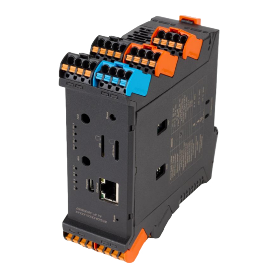
- Page 1 WEIDOS Controllers Manual Let’s connect WEIDOS-MKR1010-A1 4000003853 WEIDOS-ESP32-A1 4000003857 WEIDOS-MKR1010-LORA-A1 4000003854 WEIDOS- ESP32-LORA-A1 4000003858 WEIDOS-MKR1010-NBIOT-A1 4000003855 WEIDOS- ESP32-NBIOT-A1 4000003859...
- Page 2 22/09/2021 WEIDOS Quick Start Guide Version: 00.00.01 Prerequisite: Software: • Arduino IDE Platform Version 1.8.15 or above • USB Drivers for WEIDOS-ESP32-A1 series Hardware: • External Power Supply unit (12/24Vdc) • Micro USB type B to USB converter Page 2 / 52...
- Page 3 22/09/2021 WEIDOS Quick Start Guide Version: 00.00.01 Revision history Version Date Change log Author 2022-07 Release version Intended Audience This User Guide is intended for the following audience: • Persons in charge of introducing automation devices. • Persons who design automation systems. •...
- Page 4 22/09/2021 WEIDOS Quick Start Guide Version: 00.00.01 Preface Application Considerations and Warranty Read and Understand this Manual Please read and understand this manual before using these products. Please, also consult your comments or questions before first use. Application Consideration THE PRODUCTS CONTAINED IN THIS DOCUMENT ARE NOT SAFETY RATED. THEY SHOULD NOT BE RELIED UPON AS A SAFETY COMPONENT OR PROTECTIVE DEVICE FOR ENSURING SAFETY OF PERSONS, AS THEY ARE NOT RATED OR DESIGNED FOR SUCH PURPOSES.
- Page 5 22/09/2021 WEIDOS Quick Start Guide Version: 00.00.01 Disclaimers Weights and Dimensions Dimensions and weights are nominal, and they are not used for manufacturing purposes, even when tolerances are shown. Performance Data The performance data given in this manual is provided as a guide for the user in determining suitability and does not constitute a warranty.
- Page 6 22/09/2021 WEIDOS Quick Start Guide Version: 00.00.01 Warranty and Limitations of Liability Warranty Manufacturer’s exclusive warranty is that the products are free from defects in materials and workmanship for a period of one year (or other period if specified) from date of sale. MANUFACTURER MAKES NO REPRESENTATION OR WARRANTY, EXPRESSED OR IMPLIED, REGARDING MERCHANABILITY, NON-INFRINGEMENT, OR FITNESS FOR PARTICULAR PURPOSE OF THE PRODUCTS.
-
Page 7: Table Of Contents
22/09/2021 WEIDOS Quick Start Guide Version: 00.00.01 Content About this documentation ........................9 Symbols and notes ..........................9 Safety ............................... 12 General Safety Notice ........................12 Device Overview ............................13 General specifications ........................13 CPU Specifications ........................... 14 MKR1010 ..........................14 ESP32 ............................ - Page 8 22/09/2021 WEIDOS Quick Start Guide Version: 00.00.01 EEPROM ........................... 38 ATECCX08 Chipset........................38 µSD slot ............................ 38 3.13 Additional Communications ......................39 LoRa and LoRaWAN ......................... 39 NB IoT ............................40 Antennas ..........................41 Software Programming ..........................43 Connect WEIDOS to PC ........................43 Arduino IDE ............................
-
Page 9: About This Documentation
22/09/2021 WEIDOS Quick Start Guide Version: 00.00.01 About this documentation Symbols and notes The safety notices in this documentation are designed according to the severity of the danger. DANGER Imminent danger to life! Notes with the signal word “Danger” warn you of situations which will result in serious injury or death if you do not follow the instructions given in this manual. - Page 10 22/09/2021 WEIDOS Quick Start Guide Version: 00.00.01 Table that includes all the symbology that is used in this manual or serigraphy of Weidos products: Symbol Standard No. / Standard Symbol Meaning Standard Title Reference No. / Symbol Title IEC 60417 / 5031 / Direct Indicates that the equipment is Graphical symbols...
- Page 11 22/09/2021 WEIDOS Quick Start Guide Version: 00.00.01 • Weidos Controllers are Open-Source devices. It is required that you install the Weidos PLC in a housing, cabinet, or electric control room. Entry to the housing, cabinet, or electric control room should be limited to authorized personnel. Failure to follow these installation requirements could result in severe personal injury and/or property damage.
-
Page 12: Safety
22/09/2021 WEIDOS Quick Start Guide Version: 00.00.01 Safety This section includes general safety instructions for handling Weidos devices. Specific warning notices for specific tasks and situations are given at the appropriate places in the documentation. Failure to observe the safety and warning notices may result in damage to persons and material. General Safety Notice Consider the following steps to follow. -
Page 13: Device Overview
22/09/2021 WEIDOS Quick Start Guide Version: 00.00.01 Device Overview Within Weidos devices, there are two main variants in terms of CPUs. These variants integrate MKR1010 and the ESP32 CPU’s. Below, we specify the general specifications of Weidos controllers, main characteristics of each CPU board and basic functionalities. -
Page 14: Cpu Specifications
22/09/2021 WEIDOS Quick Start Guide Version: 00.00.01 CPU Specifications MKR1010 This section specifies the characteristics of the CPU included in the Weidos MKR1010 models, which are: WEIDOS-MKR1010-A1 WEIDOS-MKR1010-LORA-A1 WEIDOS-MKR1010-NBIOT-A1 See following table for CPU specs: Microprocessor ARM Cortex-M0 32-bit SAMD21... -
Page 15: Mechanical Dimensions
22/09/2021 WEIDOS Quick Start Guide Version: 00.00.01 Mechanical Dimensions See mechanical dimensions (mm) below: Page 15 / 52... -
Page 16: Connector Type
22/09/2021 WEIDOS Quick Start Guide Version: 00.00.01 Connector type Weidos Controllers are equipped with “PUSH IN” connector system. This technology allows for fine-wired conductors with crimped wire-end ferrules or ultrasonically welded conductors, each with a maximum cross- section of 1.5 mm² (AWG24 – AWG14), to be inserted easily through the opening in the clamping terminal without having to use tools. - Page 17 22/09/2021 WEIDOS Quick Start Guide Version: 00.00.01 Left side: Top view: Page 17 / 52...
-
Page 18: Pinout Description
22/09/2021 WEIDOS Quick Start Guide Version: 00.00.01 Pinout description In this section it is described all pins of Weidos devices: RS-485 / UART CONNECTORS Pin Number Pin Name Description A / Tx Transmit Serial Data (Half-Duplex) B / Rx Receive Serial Data (Half-Duplex) Internal GND RE-DE / NC RE-DE pin High (send) Low (receive) -
Page 19: Power Supply
22/09/2021 WEIDOS Quick Start Guide Version: 00.00.01 ANALOG OUTPUT Pin Number Pin Name Software Name Description AO_0 pin45 / AO_0 Analogue Output Vcc out ≈Vin+ (12/24Vdc) – Depending on Power Supply 5 Vout 5 VDC (Sensor Supply) 3.3 Vout 3,3 VDC (Sensor Supply) DIGITAL OUTPUT Pin Number Pin Name... -
Page 20: Reset Button
22/09/2021 WEIDOS Quick Start Guide Version: 00.00.01 Power Supply schematic: The standard, Part 1 of IEC 61010, sets the general safety requirements for the following types of electrical devices and their accessories, regardless of where use of the device is intended. The equipment must be powered from an external power source in accordance with IEC 61010-1, whose output is MBTS and is limited in power according to section 9.4 of IEC 61010-1. -
Page 21: Dip-Switches Configuration
22/09/2021 WEIDOS Quick Start Guide Version: 00.00.01 DIP-Switches Configuration Weidos devices have two DIP switches (SW1 and SW2) on one side. These switches are meant for selecting the operational mode of the configurable pins. As already mentioned, the configurable pins are the Serial RS485/UART connector and the Multifunction. To use the serial port as RS485 or UART function, please, check to the table below: To switch Multifunction pins signal between 3,3 or 5 V DC, see table below: Note: Position of pins which are not shown on the image of each operation mode, is not relevant. -
Page 22: Io's Configuration
22/09/2021 WEIDOS Quick Start Guide Version: 00.00.01 IO’s Configuration 3.10 Digital Inputs Digital Input pins are located on the following connector: Check electrical characteristics for Digital Inputs in the following table: Digital Inputs Voltage Level HIGH > 5 V DC (max. 24 V DC) Voltage Level LOW <... -
Page 23: Digital Outputs
22/09/2021 WEIDOS Quick Start Guide Version: 00.00.01 Wiring digital inputs using external voltage signal: See Digital Inputs examples of use in ArduinoIDE File > Examples > Examples for WEIDOS-XXX > Digital. Use Software Names defined in section 3.6 of this manual (Pinout description), to use Weidos pins. Digital Outputs Digital Output pins are located on the following connectors: Check electrical characteristics for Digital Outputs in the following table:... - Page 24 22/09/2021 WEIDOS Quick Start Guide Version: 00.00.01 Typical wiring connections: Weidos GND pins can also be used for common ground connection: See Digital Outputs examples of use in ArduinoIDE File > Examples > Examples for WEIDOS-XXX > Digital. Use Software Names defined in section 3.6 of this manual (Pinout description), to use Weidos pins. ATTENTION Material damage! Output from Digital Actuator must be connected to the common GND of Weidos Device.
-
Page 25: Analog / Digital Inputs (Configurable)
22/09/2021 WEIDOS Quick Start Guide Version: 00.00.01 Analog / Digital Inputs (Configurable) Analogue / Digital Input pins are located on the following connectors: Check electrical characteristics for Analog/Digital Inputs in the following table: Analog/Digital Inputs Input Range 0 to 10 V DC (max. 24 V DC when used as digital) Type of Inputs Referenced Single Ended (all analog inputs share the same common reference on the device) -
Page 26: Analogue Output
22/09/2021 WEIDOS Quick Start Guide Version: 00.00.01 The use of these inputs as analog or digital is selected via software by programming with the built-in functions analogRead() or digitalRead(). D o not depend on any external switch or additional hardware configuration. As Digital Inputs, this pins will detect HIGH state between 5 and 24Vdc, in the same way as in the opto- isolated digital inputs As Analog Inputs, this pins will detect the analog signal between 0 and 10Vdc with a resolution of 12 bits by... - Page 27 22/09/2021 WEIDOS Quick Start Guide Version: 00.00.01 Typical wiring connection: As already mentioned in Digital Outputs, Weidos GND pins can also be used for the common reference GND: See Analog Output examples of use in ArduinoIDE File > Examples > Examples for WEIDOS-XXX > Analog. Use Software Names defined in section 3.6 of this manual (Pinout description), to use Weidos pins.
-
Page 28: Multifunction Pins
22/09/2021 WEIDOS Quick Start Guide Version: 00.00.01 Multifunction Pins The multi-function pins accept different operational modes. They can be used as Digital Inputs, Digital Outputs, Interrupts or PWM signals (defined via Software PIN MODE). MF pins can only operate at 3.3Vdc or 5Vdc (configurable by switch). It is very important to check the configuration of the switches for the use of the multi-function pins before making the connection to verify the voltage in which they are configured. - Page 29 22/09/2021 WEIDOS Quick Start Guide Version: 00.00.01 Pin 43 is mean for external sensor power supply and Voltage signal level will be the same configured in DIP switches for Multifunction Pins. Maximum output current in these pins would be: Definition Conditions Typical Unit...
-
Page 30: Communications
22/09/2021 WEIDOS Quick Start Guide Version: 00.00.01 Typical Connection as Digital Outputs: 3.11 Communications In this section of the manual, the communications, and functionalities available on the default Weidos models are individually listed. UART Weidos UART communication with Peripheral devices is possible through Serial connector pins 11 and 12. The Serial Connector accepts two communication protocols (UART and RS485). - Page 31 22/09/2021 WEIDOS Quick Start Guide Version: 00.00.01 See Serial connector location in the following image: Typical Connection: Please, note that Serial communication pins work at 3.3Vdc TTL signal. See UART examples of use in ArduinoIDE File > Examples > Examples for WEIDOS-XXX > UART RS-485 Weidos accepts RS485 communication with Peripheral devices through Serial connector pins 11 and 12.
- Page 32 22/09/2021 WEIDOS Quick Start Guide Version: 00.00.01 Please check the following table to select RS485 mode: ATTENTION Material damage! Disconnect Weidos from Power Supply before any change on DIP switches configuration. See Serial connector location in the following image: For a good performance, it is recommended to use twisted pair and shielded wiring. NOTE: RS-485 pins have an internal pull-up (A) and pull-down (B) of 20KΩ.
-
Page 33: Ethernet
22/09/2021 WEIDOS Quick Start Guide Version: 00.00.01 See RS485 and ModbusRTU examples of use in ArduinoIDE File > Examples > Examples for WEIDOS-XXX > RS485 / ArduinoModbus. Ethernet Ethernet port location on the Weidos PLC Family products (Top Cover): Weidos Ethernet port is based on W5500 IC. Ethernet libraries for Arduino and ESP32 shields are compatible with the Weidos controllers. -
Page 34: Wifi
22/09/2021 WEIDOS Quick Start Guide Version: 00.00.01 WiFi Weidos devices have an integrated WiFi specific chip. In case of MKR1010 models the chip is the NinaW102 and ESP32 variants use the HT40 chip. The devices support Wi-Fi 802.11b/g/n in the 2.4 GHz ISM band and Bluetooth v4.2 (Bluetooth BR/EDR and Bluetooth low energy) communications. - Page 35 22/09/2021 WEIDOS Quick Start Guide Version: 00.00.01 See SPI connector location in the following image: MISO, MOSI and SCK connector pins for SPI bus are common to the internal communication bus. Chip Select pin is free available for the first external device. Each of the connected devices needs a single and dedicated CS pin.
-
Page 36: I2C
22/09/2021 WEIDOS Quick Start Guide Version: 00.00.01 Weidos controllers have an external I2C connector to communicate with peripheral devices (sensors or actuators) using this protocol. I2C only uses two wires to transmit data between devices: See next figure for wiring connection: SDA (Serial Data) –... -
Page 37: Other Functionalities
22/09/2021 WEIDOS Quick Start Guide Version: 00.00.01 Internal I2C Block Diagram for Weidos MKR1010 and ESP32 Controllers: I2C addresses 0x20, 0x21 and 0x23 are reserved for internal use. Using the Weidos boards in Arduino IDE, there is a library that simplifies the I2C protocols implementation. The library is defined as Wire.h See I2C examples of use in ArduinoIDE File >... -
Page 38: Eeprom
22/09/2021 WEIDOS Quick Start Guide Version: 00.00.01 EEPROM In Weidos controllers, a 512KB EEPROM memory is incorporated for hardcopy data writing/reading. It is very useful for storing critical constant values for the application. If it’s required to record indelible data in the device and microSD card is not secure enough, it is recommended to use the internal EEPROM memory for this purpose. -
Page 39: Additional Communications
22/09/2021 WEIDOS Quick Start Guide Version: 00.00.01 3.13 Additional Communications The following section includes additional communication protocols that Weidos controllers incorporate depending on the model. LoRa and LoRaWAN Compatible with the following Weidos controller models: WEIDOS-MKR1010-LORA-A1 WEIDOS-ESP32-LORA-A1 This board features the RN2483, RF technology-based SRD transceiver, which operates at a frequency of 433/868MHz from Microchip Technology. -
Page 40: Nb Iot
22/09/2021 WEIDOS Quick Start Guide Version: 00.00.01 NB IoT Compatible with the following Weidos PLC models: WEIDOS-MKR1010-NBIOT-A1 WEIDOS-ESP32-NBIOT-A1 Allows LTE Cat NB1 connectivity based on the SARA-R412M, a specialized multi-band IoT module with very low power requirements, making it perfectly suited for various IoT-based applications. Ensures data integrity between applications via secure communication protocols, notably including two-way authentication between the client and server. -
Page 41: Antennas
22/09/2021 WEIDOS Quick Start Guide Version: 00.00.01 Antennas Weidos Controllers have 2 Antenna connectors. Both connectors are SMA Female connectors. Antenna SMA Female connectors location on the Weidos PLC Family products (Top Cover): AN1: For WiFi antenna in ESP32 Models AN2: For LoRa or NBIoT antenna (Depending on Weidos Model). - Page 42 22/09/2021 WEIDOS Quick Start Guide Version: 00.00.01 Cellular General ordering data Type Bands WEIDOS-ANT-CELLULAR-MONOPOLE-A1 4000003870 600 MHz to 6 GHz WEIDOS-ANT-CELLULAR-EXT-A1 4000003871 600 MHz to 6 GHz LoRa General ordering data Type Bands WEIDOS-ANT-LORA868-DIPOLE-A1 4000003868 868 MHz & 915 MHz WEIDOS-ANT-LORA868-EXT-A1 4000003869 868 MHz &...
-
Page 43: Software Programming
22/09/2021 WEIDOS Quick Start Guide Version: 00.00.01 Software Programming Connect WEIDOS to PC Micro USB Port location on the Weidos PLC Family products (Top Cover): Connect micro-USB 2.0 port from Weidos to PC or Laptop. If using any of the Weidos models, you may need to install the following packages on your computer (MAC OSX / Windows/ Linux). -
Page 44: Arduino Ide
22/09/2021 WEIDOS Quick Start Guide Version: 00.00.01 Arduino IDE The products of the control series are programmable logic controllers. The Weidos controllers are configured, parameterized, and programmed using the Arduino IDE platform. You can download the Arduino IDE platform for any Operative System directly from this site. The steps to follow to install our equipment’s to Arduino IDE are: 1- Open the Arduino IDE, version 1.8.13 or superior. -
Page 45: Examples
22/09/2021 WEIDOS Quick Start Guide Version: 00.00.01 7- Close the “Boards Manager”. Once it is performed that steps, you are available to select your concrete Weidos Model on Arduino IDE platform and start programming your Weidos device following the instructions represented on the image that you can find below. - Page 46 22/09/2021 WEIDOS Quick Start Guide Version: 00.00.01 Page 46 / 52...
-
Page 47: Installation And Maintenance
22/09/2021 WEIDOS Quick Start Guide Version: 00.00.01 Installation and Maintenance Notes for installation: - The installation position should be free from the following: dust or oil smoke, conductive dust, corrosive or flammable gas, high temperature, condensation, and rain. - Besides, vibration and impact also affect the PLC normal operation and shorten its lifespan; electric shock, fire or misact also damages the product. - Page 48 22/09/2021 WEIDOS Quick Start Guide Version: 00.00.01 Provide adequate clearance for cooling and wiring Weidos. Is designed for natural convection cooling. For proper cooling, you must provide a clearance of at least 20 cm above and below the devices. Also, allow at least 20 cm of depth between the front of the modules and the inside of the enclosure.
- Page 49 22/09/2021 WEIDOS Quick Start Guide Version: 00.00.01 - All types of radio communication devices, including mobile phones and personal handy-phone systems (PHS), must be kept more than 25cm away from the PLC in all directions. Failure to observe this precaution exposes malfunctions caused by excess of temperature.
-
Page 50: Annexes
22/09/2021 WEIDOS Quick Start Guide Version: 00.00.01 Annexes A1. Ferrite installation Weidos devices include a TRM-16-8-16E-WE Epoxy coated ferrite core, to act as a frequency high impedance noise filter in hazardous environments. Coated ferrite core has rounded corners to reduce load on cable and is made of Mn-Zn soft, epoxy coated. The use of this ferrite for industrial uses is mandatory and necessary. - Page 51 22/09/2021 WEIDOS Quick Start Guide Version: 00.00.01 Impedance vs Frequency table depending on number of turns arround the ferrite (blue: 1 turn, yellow: 2 turns, red: 3 turns): Page 51 / 52...
- Page 52 22/09/2021 WEIDOS Quick Start Guide Version: 00.00.01 Weidmüller – Your Partner in Industrial Connectivity As experienced experts we support our customers and partners around the world with products, solutions, and services in the industrial environment of power, signal and data. We are at home in their industries and markets and know the technological challenges of tomorrow.
Need help?
Do you have a question about the WEIDOS-MKR1010-A1 and is the answer not in the manual?
Questions and answers