Sign In
Upload
Manuals
Brands
Hioki Manuals
Measuring Instruments
RM3545-02
Hioki RM3545-02 Manuals
Manuals and User Guides for Hioki RM3545-02. We have
2
Hioki RM3545-02 manuals available for free PDF download: Instruction Manual
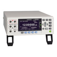
Hioki RM3545-02 Instruction Manual (364 pages)
Resistance Meter
Brand:
Hioki
| Category:
Measuring Instruments
| Size: 6 MB
Table of Contents
Table of Contents
5
Introduction
9
Verifying Package Contents
10
Safety Information
12
Measurement
13
Operating Precautions
14
Measurement
15
Measurement
16
Measurement
17
Measurement
18
Measurement
22
Measurement
24
Measurement
25
Chapter 1 Overview
27
Product Overview and Features
27
Measurement
28
Measurement
29
Names and Functions of Parts
30
Measurement
31
Measurement Process
33
Appendix 11Measuring Contact Resistance
34
Specifications (P
34
Screen Organization and Operation Overview
35
Compliant Resistance Measure- Ment
36
Measurement
37
Measurement
38
Measurement
39
Measurement
40
Checking the Measurement Target
41
Measurement
42
Chapter 2 Measurement Preparations
43
Connecting the Power Cord
43
Appendix 17Rack Mounting
43
Connecting Measurement Leads
44
Connecting Z2001 Temperature Sensor or Thermometer with Analog Output (When Using the TC or ΔT)
45
Connecting the Z2001 Temperature Sensor
45
Connecting an Analog Output Thermometer
45
Measurement
45
Measurement
46
Measurement
47
Measurement
48
Measurement
49
Installing the Multiplexer Unit
50
Turning the Power on and off
51
Turning on the Instrument with the Main Power Switch
51
Turning off the Instrument with the Main Power Switch
51
Canceling the Standby State
51
Placing the Instrument in the Standby State
52
Appendix 20Adjustment Procedure
51
Pre-Operation Inspection
53
Chapter 3 Basic Measurements
55
Checking the Measurement Target
56
Selecting the Measurement Range
57
Setting the Measurement Speed
58
Connecting Measurement Leads to the Measurement Target
59
Checking Measured Values
60
Switching the Display
60
Measurement
60
Measurement
62
Confirming Measurement Faults
63
Measurement
63
Measurement
64
Measurement
65
Measurement
66
Measurement
67
Holding Measured Values
68
Measurement
69
Chapter 4 Customizing Measurement Conditions
71
Switching to Low-Power Resistance Measurement
72
Switching Measurement Currents (100 Mω to 100 Ω)
74
Zero Adjustment
76
Stabilizing Measured Values (Averaging Function)
81
Correcting for the Effects of Temperature (Temperature Correction (TC))
83
Correcting Measured Values and Displaying Physical Properties Other than Resistance Values (Scaling Function)
85
Changing the Number of Measured Value Digits
89
Compensating for Thermal EMF Offset (Offset Voltage Compensation - OVC)
90
Setting Pre-Measurement Delay
92
Checking for Poor or Improper Contact (Contact Check Function)
96
Improving Probe Contact (Contact Improver Function)
98
Maintaining Measurement Precision (Self-Calibration)
100
Increasing the Precision of the 100 MΩ Range (100 MΩ High-Precision Mode)
104
Chapter 5 Judgment, Statistics
105
And Conversion
105
Functions
105
Judging Measured Values (Comparator Function)
106
Enabling and Disabling the Comparator Function
108
Decide According to Upper/Lower Thresholds (ABS Mode)
109
Decide According to Reference Value and Tolerance (REF% Mode)
111
Checking Judgments Using Sound (Judgment Sound Setting Function)
113
Checking Judgments with the L2105 LED Comparator Attachment (Option)
115
Classifying Measurement Results (bin Measurement Function)
116
Performing Statistical Calculations on Measured Values
119
Using Statistical Calculations
120
Confirming, Printing, and Erasing Calculation Results
122
Performing Temperature Rise Test (Temperature Conversion Function (ΔT))
124
Chapter 6 Saving and Loading Panels
127
Saving Measurement Conditions (Panel Save Function)
128
Loading Measurement Conditions (Panel Load Function)
129
Preventing Loading of Zero-Adjustment Values
130
Changing Panel Names
131
Deleting Panel Data
132
Chapter 7 System Settings
133
Disabling and Enabling Key Operations
133
Disabling and Enabling Key Operations
134
Disabling Key Operations (Key-Lock Function)
134
Re-Enabling Key Operations (Key-Lock Cancel)
135
Enabling or Disabling the Key Beeper
136
Power Line Frequency Manual Setting
137
Adjusting Screen Contrast
139
Adjusting the Backlight
140
Setting the Clock
141
Initializing (Reset)
142
Default Settings
144
Chapter 8 Multiplexer
147
About the Multiplexer
148
Connector Type and Pinouts
150
Connector Type and Pinouts
151
About Multiplexer Wiring
153
Internal Circuitry
154
Electrical Specifications
155
Multiplexer Settings
156
Configuring Multiplexer Settings
156
Customizing Channel Pin Allocation
160
Setting Basic Measurement Conditions and Total Judgment Conditions for Individual Channels
164
Customizing Measurement Conditions for Individual Channels
168
Measuring with the Multiplexer
169
Measuring While Switching Channels Manually
169
Performing Scan Measurement
170
Zero Adjustment (When a Multiplexer Unit Has Been Installed)
171
Canceling Zero-Adjustment
172
Performing the Multiplexer Unit Self-Test
174
Example Connections and Settings
175
Chapter 9 D/A Output
181
Connecting D/A Output
181
D/A Output Specifications
182
Chapter 10 External Control (EXT I/O)
183
External Input/Output Connector and Signals
184
Switching between Current Sink (NPN) and Current Source (PNP)
184
Connector Type and Signal Pinouts
185
Signal Descriptions
187
Timing Chart
193
From Start of Measurement to Acquisition of Judgment Results
193
BCD Signal Timing
197
Contact Improver Timing
202
Panel Load Timing
203
Multiplexer Timing
204
Output Signal State at Power-On
207
Acquisition Process When Using an External Trigger
208
Internal Circuitry
210
Electrical Specifications
212
Connection Examples
213
External I/O Settings
214
Setting Measurement Start Conditions (Trigger Source)
214
Setting the TRIG Signal Logic
216
Eliminating TRIG/PRINT Signal Chatter (Filter Function)
218
Setting EOM Signal
220
Switching Output Modes (JUDGE Mode/ BCD Mode)
222
Checking External Control
223
Performing an I/O Test (EXT I/O Test Function)
223
Supplied Connector Assembly
225
Chapter 11 Communications
227
(USB/ RS-232C/ GP-IB Interface)
227
Overview and Features
227
Overview and Features
228
Preparations before Use (Connections and Settings)
229
Using the USB Interface
229
Using the RS-232C Interface
232
Using the GP-IB Interface (RM3545-01 Only)
236
Controlling the Instrument with Commands and Acquiring Data
238
Remote and Local States
238
Displaying Communications Commands (Communications Monitor Function)
239
Acquiring Measured Values at Once (Data Memory Function)
241
Auto-Exporting Measured Values (at End of Measurement) (Data Output Function)
242
Connecting the Printer to the Instrument
245
Chapter 12 Printing (Using an RS-232C Printer)
245
Printing
248
Printing Measured Values and Comparator Judgments
248
Printing List of Measurement Conditions and Settings
249
Printing Statistical Calculation Results
253
Chapter 13 Specifications
257
Instrument Specifications
257
Measurement Ranges
257
Measurement Method
257
Measurement Specifications
258
About Instrument Accuracy
265
Functions
266
Chapter 13 Specifications 249
276
Interface
277
Environment and Safety Specifications
284
Accessories
284
Options
284
Z3003 Multiplexer Unit
285
General Specifications
285
Measurement Specifications
287
About Instrument Accuracy
288
Functions
289
Environment and Safety Specifications
289
Accessories
289
Chapter 14 Maintenance and Service
291
Troubleshooting
292
Q&A (Frequently Asked Questions)
292
Error Displays and Remedies
304
Replacing the Measurement Circuit's Protective Fuse
308
Inspection and Repair
309
Disposing of the Instrument
310
Removing the Lithium Battery
310
Appendix
313
Appendix 1 Block Diagram
313
Appendix 2 Four-Terminal (Voltage-Drop) Method
314
Appendix 3 DC and AC Measurement
315
Appendix 4 Temperature Correction (TC) Function
316
Appendix 5 Temperature Conversion (ΔT) Function
318
Appendix 6 Zero Adjustment
319
Appendix 7 Unstable Measured Values
324
Appendix 8 Mitigating Noise
331
Appendix 9 Effect of Thermal EMF
335
On a Printed Circuit Board
337
Appendix 13Making Your Own Measurement
341
Leads, Making Connections to the Multiplexer
341
Appendix 14Checking Measurement Faults
344
Appendix 15Using the Instrument with a
345
Withstanding Voltage Tester
345
Appendix 16Measurement Leads (Options)
346
Appendix 18Outline Drawing
349
Appendix 19Calibration
350
Advertisement
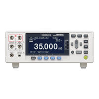
Hioki RM3545-02 Instruction Manual (100 pages)
RESISTANCE METER, COMMUNICATION COMMAND
Brand:
Hioki
| Category:
Measuring Instruments
| Size: 2 MB
Table of Contents
Table of Contents
2
1 Introduction
6
Message Format
6
Output Queue and Input Buffer
10
Status Byte Register
11
Event Registers
13
Initialization Items
16
Command Execution Time
17
Errors During Communications
17
2 Message List
18
3 Message Reference
26
Message Reference Interpretation
26
Standard Commands
27
System Data Command
27
Idn
27
Internal Operation Command
27
Rst
27
Tst
27
Synchronization Commands
28
Opc
28
Wai
28
Status and Event Control Commands
28
Cls
28
Ese
28
Esr
29
Sre
29
Stb
30
Trg
30
Device-Specific Commands
30
Event Status Register
30
Ese0
30
Esr0
31
Ese1
31
Esr1
31
Reading Measured Values
31
Fetch:temperature
34
Read
34
Measure:resistance:lp
36
Measure:temperature
36
Abort
36
Zero Adjustment
37
Adjust:clear
37
Measurement Speed
38
Sample:rate
38
Averaging Function
38
Calculate:average:state
38
Calculate:average:count
38
Comparator
38
Calculate:limit:state
38
Calculate:limit:beeper
39
Calculate:limit:mode
39
Calculate:limit:upper
39
Calculate:limit:lower
39
Calculate:limit:reference
40
Calculate:limit:percent
40
Calculate:limit:result
40
Calculate:limit:judge:condition
40
Calculate:limit:judge
41
Calculate:limit:judge:total
41
BIN Function RM3545 RM3545A
41
Calculate:bin:state
41
Calculate:bin:enable
41
Calculate:bin:mode
42
Calculate:bin:upper
42
Calculate:bin:lower
42
Calculate:bin:reference
42
Calculate:bin:percent
42
Calculate:bin:result
43
Statistical Functions RM3545 RM3545A
43
Calculate:statistics:state
43
Calculate:statistics:clear
43
Calculate:statistics:number
43
Calculate:statistics:mean
43
Calculate:statistics:maximum
44
Calculate:statistics:minimum
44
Calculate:statistics:limit
44
Calculate:statistics:bin
44
Calculate:statistics:deviation
44
Calculate:statistics:cp
44
Scaling
44
Calculate:scaling:state
44
Calculate:scaling:parametera
45
Calculate:scaling:parameterb
45
Calculate:scaling:unit
45
Temperature Conversion (ΔT) RM3545 RM3545A
45
Calculate:tconversion:delta:state
45
Calculate:tconversion:delta:parameter
45
Temperature Correction (TC)
46
Calculate:tcorrect:state
46
Calculate:tcorrect:parameter
46
LCD Settings
46
Display:contrast
46
Display:backlight
46
Memory Functions RM3545 RM3545A
47
Memory:state
47
Memory:clear
47
Memory:count
47
Memory:data
47
Hold
47
[:Sense:]Hold:auto
47
[:Sense:]Hold:state
48
[:Sense:]Hold:off
48
Multiplexer Settings RM3545 RM3545A
48
[:Sense:]Wire
48
[:Sense:]Scan:mode
48
[:Sense:]Scan:state
48
[:Sense:]Scan:fail:stop
49
[:Sense:]Ch
50
Multiplexer Channel Reset RM3545 RM3545A
51
Low-Power Resistance Measurement RM3545 RM3545A
52
Pure Resistance Measurement RM3545A
52
Measurement Range
52
[:Sense:]Resistance:range
53
[:Sense:]Resistance:range:auto
53
[:Sense:]Resistance:lp:range
53
100MΩ Range High Precision Function RM3545 RM3545A
54
[:Sense:]Resistance:precision
54
Switching Measurement Current RM3545 RM3545A
54
[:Sense:]Resistance:current
54
Offset Voltage Correction Function (OVC) RM3545 RM3545A
55
[:Sense:]Resistance:ovc
55
Contact Improver RM3545 RM3545A
55
[:Sense:]Resistance:cimprove
55
Current Error Mode
55
[:Sense:]Resistance:error:currentcheck
55
Sense:resistance:error:over
56
Contact Check RM3545 RM3545A
56
[:Sense:]Resistance:contactcheck
56
[:Sense:]Resistance:lp:contactcheck
56
Setting Number of Digits
56
[:Sense:]Resistance:digits
56
Temperature Measurement (Analog Input) RM3545 RM3545A
57
[:Sense:]Temperature:sensor
57
[:Sense:]Temperature:parameter
57
Triggering
58
Initiate:continuous
58
Initiate:immediate
58
Trigger:source
58
Trigger:edge
62
Delay RM3545 RM3545A
62
Trigger:delay
62
Trigger:delay:auto
62
Self-Calibration RM3545 RM3545A
62
System:calibration
62
System:calibration:auto
62
Saving and Reading Measurement Conditions
63
System:panel:name
63
System:panel:clear
63
Key-Lock
64
System:klock
64
Line Frequency
64
System:lfrequency
64
Clock RM3545 RM3545A
64
System:date
64
System:time
65
Key Beeper
65
System:beeper:state
65
Communications Settings
65
System:local
65
System:dataout
65
System:header
66
System:terminator
66
System:communicate
66
System:communicate:monitor
66
System:communicate:lan:ipaddress
67
System:communicate:lan:smask
67
System:communicate:lan:gateway
67
System:communicate:lan:control
67
System:communicate:lan:mac
68
System:communicate:lan:update
68
System:communicate:rs232C:speed
68
System Reset
68
Ext I/O
69
Io:mode
69
Io:input
69
Io:output
69
Io:filter:state
69
Io:filter:time
69
Io:judge:mode
70
Io:eom:mode
70
Io:eom:pulse
70
Multiplexer Unit RM3545 RM3545A
71
Unit:idn
71
Unit:scount
71
Unit:test
71
4 Multiplexer Commands
72
Multiplexer Settings
72
Multiplexer Measurement
73
5 Data Exporting Methods
76
6 Examples of Communication Commands
79
Confirmation before Measurement
79
Setting Measurement Conditions
79
Simple Resistance Measurement
79
Resistance Measurement Using Computer Keys
79
Measurement by External Trigger 1
80
Measurement by External Trigger 2
80
LAN Communication Setting Example RM3545A
80
7 Sample Programs
81
Using Visual Basic
81
Using Visual C
89
8 Device Compliance Statement [GP-IB]
98
Advertisement
Related Products
Hioki RM3544
Hioki RM3544-01
Hioki RM3548
Hioki RM3545
Hioki RM3545-01
Hioki RM3542-50
Hioki RM3542A Series
Hioki RM3542-51
Hioki RM3545A-1
Hioki RM3545A-2
Hioki Categories
Measuring Instruments
Test Equipment
Data Loggers
Multimeter
Accessories
More Hioki Manuals
Login
Sign In
OR
Sign in with Facebook
Sign in with Google
Upload manual
Upload from disk
Upload from URL