
Related Manuals for Hioki SM-8213


Summary of Contents for Hioki SM-8213
- Page 1 99 Washington Street Melrose, MA 02176 Phone 781-665-1400 Toll Free 1-800-517-8431 Visit us at www.TestEquipmentDepot.com Instruction Manual SM-8213 SM-8215 SM-8220 SUPER MEGOHMMETER March 2013 Revised edition 5 SM8213A981-05 13-03H...
- Page 3 The meter outputs a high test voltage – 1000 V maximum for the SM-8220/8215, and 100 V maximum for the SM-8213 – to apply across the sample circuit. Operators are requested to read this operation manual thoroughly before trying to operate the instrument for safety and to prevent electrical shock and damage to the measured circuit.
- Page 4 1. Safety Precautions Operators of the SM-8200 Series super megohmmeter are requested to read this operation manual thoroughly before operation for safety and to obtain best performance. Operators are also requested to strictly observe all the DANGER, WARNING, and CAUTION notices in this manual and on the instrument to prevent injury and damage.
- Page 5 1.2 Symbols on the Super Megohmmeter Symbol Meaning Description WARNING This symbol is shown at pats whose usage needs reference to the operation manual. DANGER – This symbol is shown at the Rx ““/”+” HIGH VOLTAGE Measuring terminals which carry a high voltage HAZARD to be applied across the circuit to be measured.
- Page 6 If repair or internal readjustment is needed, contact your contact your dealer or Hioki representative. CAUTION ■Before turning on the power switch for the instrument, check that the VOLTAGE SELECTOR switches are set for your local AC line voltage.
- Page 7 ■ If the instrument generates smoke or smell, unplug the power cord. If such an instrument is kept powered on, it may cause a fire. contact your dealer or Hioki representative for repair. ■Do not operate the instrument with a wet hand. This may cause electrical shock.
- Page 8 For optional accessories, see 9. OPTIONAL ACCESSORIES. Measuring Voltage Ranges: SM-8213 – 5, 10, 15, 25, 50 and 100 V SM-8215 – 50, 100, 250, 500 and 1000 V SM-8220 – 10, 25, 50, 100, 250, 500 and 1000 V Measuring Resistance Range: Ω...
- Page 9 Organization of This Operation Manual This operation manual contains the following 10 sections. 1. PREPARATION BEFORE OPERATION This section describes precautions for unpacking and AC line voltage setting. 2. SPECIFICATIONS This section describes the specifications for the SM-8200 Series super megohmmeters and optional accessories.
-
Page 11: Table Of Contents
C O N T E N T S 1. PREPARATION BEFORE OPERATION ..... . . 1 1.1 Unpacking and Checking of the Contents ....1 1.2 Operating AC Line Voltage . - Page 12 6.6 Setting a Variety of Functions ..... . . 2 8 6.6.1 Setting the Timer ....... 2 8 6.6.2 Setting the Comparison GO/NO Judgment Level .
-
Page 13: Preparation Before Operation
Note: The shorting plug is plugged to the HV-EN socket when shipping from factory. CAUTION When plugging the shorting plug, make sure that the power is turned off, otherwise, there is an electric shock hazard. Upon checking the instrument and accessories, if any damage is found, immediately contact your dealer or Hioki representative. -
Page 14: Operating Ac Line Voltage
1.2 Operating AC Line Voltage The super megohmemeter can be operated from one of the following AC power source when the VOLTAGE SELECTOR switches are set accordingly. AC Line Voltage Frequency 100 V ±10% 50/60 Hz 120 V ±10% 50/60 Hz 220 V ±10% 50/60 Hz 240 V +10V, ... -
Page 15: Checking The Fuse Amperage
CAUTION The VOLTAGE SELECTOR switches have two positions – up and down. Slide the switch lever to either position until it stops. Do not leave the lever at a neutral position. If the lever is set at a neutral position, a normal function cannot be obtained, and it will cause a failure. -
Page 16: Grounding The Chassis
Fuse Replacement The fuse is inserted in the FUSE holder (Fig. 1.2) on the rear of the unit. Remove the cap, and replace the fuse with a new one with a correct amperage. To remove the cap of the fuse holder, use a 4 mm Phillips screwdriver, and turn the cap counterclockwise. -
Page 17: Warm-Up Period
1.6 Warm-up Period To obtain the performance of published specifications, allow the SM-8200 Series super megohmmeter to warm for a minimum of 30 minutes. -
Page 18: Specifications
SPECIFICATIONS 2.1 Measuring Performance 1) Electrical Resistance Measurement SM-8213(RANGE : ×1 , ×10 , ×10 , ×10 , ×10 , or ×10 Target Voltage Measurement Range (MΩ) [RANGE=×10 × 10 to 20 × 10 100 V 0.25 × 10 to 10 × 10 50 V 0.125 ×... -
Page 19: Function Specifications
1) CHARGE Function This function charges the sample to be measured by applying the Selected measuring voltage when the CHARGE switch is pushed. Internal Resistance SM-8213: Approx. 0Ω SM-8215: Approx. 30kΩ SM-8220: Approx. 30kΩ 2) DISCHARGE Function This function discharges a residual voltage on the sample after measurement when the DISCHARGE switch is pushed. -
Page 20: Other Electrical And Physical Data
2.3 Other Electrical and Physical Data 1) Environmental temperature and Humidity Operation: 0 to 40℃ (SM-8213/8215),80% RH or less (non-condensating) 5 to 35℃ (SM-8220),80% RH or less (non-condensating) Storage: 5 to 45℃,80% RH or less(non-condensating) 2) Power Requirements AC 100 V, 120 V, 220 V, ±10%, 240 V +10 V, 10% 50/60 Hz 3) Power Consumption Approx. -
Page 21: List Of Measurement Ranges And Guaranteed Accuracy Ranges By Model
2.5 List of Measurement Ranges and Guaranteed Accuracy Ranges by Model SM-8213 Range/measurement range (with guaranteed accuracy range in parentheses)[MΩ] ×1 ×10 ×10 ×10 ×10 ×10 2 3 4 5 Voltage 0 1 2 3 4 5 0.025×10 0.025×10 0.025×10 0.025×10... - Page 22 SM-8215 Range/measurement range (with guaranteed accuracy range in parentheses) [MΩ] ×1 ×10 ×10 ×10 ×10 ×10 Voltage 2 3 4 5 0 1 2 3 4 5 0.250×10 0.250×10 0.250×10 0.250×10 0.250×10 0.250×10 : : : : : : 0 1...
- Page 23 SM-8220 Range/measurement range (with guaranteed accuracy range in parentheses) Voltage [MΩ] ×1 ×10 ×10 ×10 ×10 ×10 ×10 ×10 ×10 Voltage 2 3 4 5 6 7 8 0 1 2 3 4 5 6 7 8 0.050×10 0.050×10 0.050×10 0.050×10 0.050×10 0.050×10...
- Page 24 3. OPEARATING PRINCIPLE The SM-8200 Series super megohmmeters consist of a constant voltage power supply and a high sensitive current measuring section to be combined to compose a resistance measuring circuit. The current measuring section is composed of a current detective resistor, low drift voltage amplifier and an integrator-type A/D converter.
-
Page 25: Familiarization With Controls And Parts
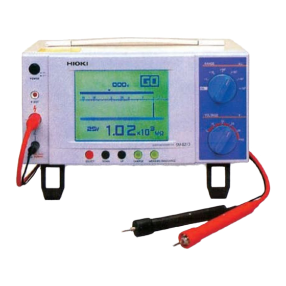
4. FAMILIARIZATION WITH CONTROLS AND PARTS 4.1 Front Panel The figure below shows the front panel of the SM-8200 Series. However, note that the values for the two knobs on the right are represented by those of the SM-8213. ① ②... - Page 26 ⑤ SELECT Switch: This switch moves the cursor in the LCD display to the desired item set it. This switch also acts as a STOP switch; this switch makes the voltage on the Rx /+ measuring terminals OFF when it is pressed while the measuring voltage is being applied.
-
Page 27: Rear Panel
4.2 Rear Panel The figure below shows the rear panel of the SM-8200 Series. However, note that the VOLTAGE SELECTOR switches are set for the operation from 100 V AC line. ⑱ ⑰ ⑯ ⑮ ⑫ ⑬ ⑭ Fig. 4.2 Rear Panel ⑫... - Page 28 ⑯ External Input/Output Terminal Block: This terminal block carries signals measured result judgment outputs, optional DC output, and remote signal input. For details, see the following sections; 6.5 Comparison and Judgment Function 8. MEMORY CONTROLLED MEASUREMENT 9.2 DC Signal Output ⑰...
-
Page 29: Measuring Display
4.3 Measuring Display In the measuring mode, the LCD display shows the resultant measured resistance value and its NO/GO judgment, as well as the measuring voltage and time. ⑦ ⑥ ⑧ 000 s ⑨ .5 1 2 5 10 20 ⑤... -
Page 30: Measuring Condition Setting Display
4.4 Measuring Condition Setting Display The LCD display showing the measuring condition setting. ⑬ 000 s .5 1 2 5 10 20 ⑫ 100V 3 10 MΩ LOCK M.S ET ⑭ ⑩ ⑪ Fig. 4.4 ⑩ Status and Mode Notice: When the MEASURE/DISCHARGE selector switch is set to the DISCHARGE position, press the SELECT switch to enter the setting mode, and the selected mode is shown in this box. -
Page 31: Meanings Of The Status And Mode Notices
4.5 Meanings of the Status and Mode Notices This describes the meanings of the status and mode notice in the lower left corner of the LCD display. 1) LOCK (Interlocking): The test voltage applying circuit is interlocked, an measurement is not ready, yet. This notice is shown when the interlocking function is in use, but the HV-EN plug or measuring rod plug is not plugged into the connector. -
Page 32: Preparation For A Measurement
5. PREPARATION FOR A MEASUREMENT WARNING Make sure, before turning the instrument on, that the VOLTAGE SELECTOR switches on the rear of the unit are properly se t to the positions in agreement with the local AC line voltage. If the agree- ment is failed, the unit may break a fire or burning. -
Page 33: Self-Calibration 1
4) Confirm that accessory shorting plug inserted into HV-EN connector on the rear the unit. 5) Leave the Rx /+ measuring terminals free at this stage – do not connect the measuring rods and the sample to be measured to the terminals. 6) Set the RANGE selector switch to the ×1 position –... -
Page 34: Check The Measuring Rods
5.4 Check the Measuring Rods 1) Confirm that V.OUT indicator turns off and that the Rx /+ measuring terminals don’t carry a measuring voltage across them. 2) Plug the accessory measuring rods to the Rx +/ measuring terminals until they are stopped. (Red measuring rod to the Rx measuring terminal / Black measuring rod to the Rx + measuring terminal) 3) Set the RANGE selector switch to the ×1 position –... -
Page 35: Basic Procedures For A Measurement
5.5 Basic Procedures for a Measurement <Preparation> VOLTAGE SELCTOR Switch Setting VOLTAGE SELCTOR switch setting HV-EN shorting plug insertion Power ON 30-minute warm-up Calibration Measuring Rods checks <Measurement> Sample Connection VOLTAGE SELCTOR switch setting HV-EN shorting plug insertion Control Setting Measuring Voltage Setting Range Setting Timer Setting -- (See 6.6.1) -
Page 36: Measurement
6. MEASUREMENT 6.1 Measuring Method 1) Plug the accessory measuring rods to the Rx +/ measuring terminals until they are stopped. ■ Red measuring rod to the Rx measuring terminal ■ Black measuring rod to the Rx + measuring terminal Note that each terminal has an incomple te plugging detection switch. - Page 37 becomes a significant parame ter for the measuring conditions. In most cases, the value of 1 minute after voltage charging is read as a 1 minute rate value. The integrated timer can de termine the value at 1 minute after voltage charging. For details, see 6.6. Note 3: When a measuring jig is used, it is recommended to provide an interlocking switch with it for safety.
-
Page 38: Interlocking Function - Using The Hv-En Connector
6.4 Interlocking Function – Using the HV-EN Connector The super megohmmeter generates a high voltage to be used as a testing power source. I t is dangerous if this measuring voltage is output to the sample not ready for measurement, yet. To protect the operator from a hazard of e lectrical shock, the HV-EN (high voltage enable ) connector is provided on the rear of the unit to provide an interlocking function in combination with a measuring jig. -
Page 39: Comparison And Judgment Function
6.5 Comparison and Judgment Function This function is provided to sound a built-in buzzer, and turn on the COMP OUT G/+ te rminals when the measured insulation resistance is lower than the preset judgment value and make the COMP OUT G/+ terminals are of open collector as shown as an equivalent circuit in Fig. -
Page 40: Setting A Variety Of Functions
6.6 Setting a Variety of Functions A variety of useful functions can be set when the RANGE selector switch is set to any position other than the CAL , and by using the SELECT, UP and DOWN switches. Each time the SELECT switch is pushed, the LCD display is changed in the order of the Measuring Display →... -
Page 41: Setting Buzzer Sound On/Off
1) Set the VOLTAGE selector switch to 100 V . 2) Set the RANGE selector switch to ×10 3) Press the SELECT switch 3 times to show the COMP indication in the lower left area of the LCD for the comparison GO/NO judgment level. 4) Using the UP and DOWN switches, set the GO/NO judgment level to MΩ... - Page 42 RANGE ×10 010 s .5 1 2 5 10 20 VOLTAGE 2 100V 10 MΩ C. SET Fig. 6.6.4 SELECT DO WN CHAR GE MEA SUR E/DIS CHA RG E 1) Set the VOLTAGE selector switch to 100 V . 2) Set the RANGE selector switch to ×10 3) Press the SELECT switch to show the C.
-
Page 43: Changes In The Current Flowing Through Insulators
6.7 Changes in the Current Flowing through an Insulator In insulation resistance measure ments, a large amount of current flows upon the application of the test voltage to the insulator. The current gradually reduces its value with time, but it takes a time until the value becomes stable and fixed. -
Page 44: Connectivity Precautions
Have series resistors R ,…R . Therefore, a measurement of R only very difficult. said that, with some insulation resistance measurements, it takes several hours to a few days for the leakage curre nt to stabilize. This is not practical. To avoid this problem, a method is customarily used in the insulation resistance measurement for convenience to read the resistance value one minute after charging the test voltage to the sample. -
Page 45: When Using An Optional Electrode For Plate Samples Or Shield Box
6.8.2 When Using an Optional Electrode for Plate Samples or Shield Box When using an electrode for plate samples (for example the SME-8310; or the SME-8350 shield box, etc.), which is an option designed specifically for use with the megohmmeter, the following guidelines should be observed when wiring the instrument and performing measurements: To prevent the hazard of e lectric shock, be sure to ground either the ground pin of the 3-pin power cable or the ground terminal on the rear... - Page 46 7. RS-232C INTERFACE 7.1 RS-232C Communication Commands Mnemonic Contents Format Measuring Data Output Format: R Response: ****E*, Judgment [GO] 0 or [NO] 1 Example: 10.0E4, 0 Starting a Measure ment Format: M Response: 0 (valid) or 1 (invalid) Starting a Charging Format: C Response: 0 (valid) or 1 (invalid) Stopping Forcedly...
-
Page 47: Applications Of Commands
7.2 Applications of Commands 1) After each command transmission, make sure to receive the response. 2) For R command, a state only response will be received, depending upon the conditions at such a time. Even during measurement, a state 7 only response will be received when the timer is functioning. -
Page 48: Printer Output
2) For connection with an NEC PC-9801 Series personal computer, use a straight 9-pin to 25-pin cable. 《 9-pin》 《 25-pin》 7.4 Printer Output Via the RS-232C interface, measured data can be output to an optional printer, 9442. [Printer Output Procedures] 1) Connect the RS-232C interface connector on the rear of the unit, to the optional printer via the dedicated connection cord. -
Page 49: Remotely Controlled Measurement
8. REMOTELY CONTROLLED MEASUREMENT A measurement can be remotely controlled by shorting the “G” and “+” terminals of the REMOTE IN of the External Input/Output terminal block on the rear of the unit. When the terminals are shorted by a remote switch, a measurement will start, and when opened the measurement is ended. - Page 51 Note 1: When the measuring time is set with the incorporated timer, the timer has a priority over a remotely controlled switch actuation. When the REMOTE IN “G” and “+” terminals are closed, a measurement will start. The measurement will automatically end when the time set with the timer is up.
-
Page 52: Introduction Of Options
9. INTRODUNTION OF OPTIONS With the SM-8200 Series super megohmmeters, any of the following options can be provided as needed. However, note that some of them can be installed at factory. 9.1 DC Signal Outputs Either one of two different types of DC signal outputs can be optionally installed with the unit at factory. - Page 53 A DC measuring instrument like a HI OKI chart recorder can be connected to these terminals. For permanent data recording, a HIOKI chart recorder is recommended for better technical follow-up, including a supply of a variety of recording charts and technical service.
- Page 54 Target voltage 250V 1.25 6.25 12.5 Displayed value Output voltage Target voltage 500V 12.5 Displayed value Output voltage Target voltage 1000V Displayed value Output voltage Example ・ SM-8220 Target voltage : 500V RANGE : ×10 Measurement range : 2.5×10 MΩ to 100×10 MΩ...
- Page 55 A DC measuring instrument like a HI OKI chart recorder whose input impedance is greater than 10 MΩ can be connected to these terminals. For permanent data recording, a HIOKI chart recorder is recommended for better technical follow-up, including a supply of a varie ty of recording charts and technical service.
- Page 56 Target voltage 1000V Displayed value Output voltage Example ・ SM-8220 Target voltage : 100V RANGE : ×10 Measurement range : 0.5×10 MΩ to 20×10 MΩ ・ Output voltage of RI-8000 Output range : 0.5×10 MΩ to 5×10 MΩ Output voltage : 10V/0.5×10 MΩ...
-
Page 57: Maintenance And Miscelaneous
Periodical maintenance, including checking and calibration is required for the MS-8200 super megohmmeter to pe rform reliable measurements and prevent a trouble and accident. If necessary, ask your dealer or Hioki representative to do such a service as periodical checking, calibration and routine maintenance. 10.1 Periodical Checking To keep your instrument its at best condition, the following checking is required at monthly periods. -
Page 58: External Appearance
11. EXTERNAL APPEARANCE Approx.139 (H) Unit: mm Test Equipment Depot - 800.517.8431 - 99 Washington Street Melrose, MA 02176 TestEquipmentDepot.com...
Need help?
Do you have a question about the SM-8213 and is the answer not in the manual?
Questions and answers