
Related Manuals for Mount-It! MI-7285


Summary of Contents for Mount-It! MI-7285
- Page 1 MI-7285 Scan this QR code for product information, videos, and assembly assistance. ON-WALL TV CABLE CONCEALER KIT...
-
Page 2: Package Contents
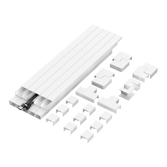
PACKAGE CONTENTS Thank you for choosing Mount-It A×10 B×6 C×1 D×1 Mount-It! Straight Channel 15.7" each Flat 90° Interior 90° Exterior 90° Mount-It! E×9 F×2 G×20 H×20 WARNING Straight Coupling T-Fitting Concrete Anchor Lag Screws Ф6×30mm ST3.8×30mm 1. Due to the extremely sticky nature of the tape, please plan your installation well in advance of installation to Please refer to the diagram below for instructions on how to use each connector and select your avoid removing and reinstalling the cable channel. - Page 3 Installation Option 1: Adhesive Tape Step 3 (Not suitable for rough or uneven surfaces) Optional: Cut the Straight Channel as Needed Step 1 • If any of the Straight Channels (#A) exceed the required length, mark the correct length, and cut in the marked location with a hand saw.
- Page 4 Step 6 Step 9 Remove Adhesive Backing Install the Connectors & Covers • Remove the adhesive backing from the rear of the Straight Channels (#A) exposing the mounting tape • First, reinstall the covers onto the Straight Channel, then install the connectors onto any corners or beneath.
-
Page 5: Step 5 Remove The Cover
Step 2 Step 4 Measure Determine Final Placement • First, plan the route and mark it with a pencil, then measure the distance and determine the number of • Using a bubble level to ensure straightness, hold the Straight Channels (#A) in their positions and mark cable channels needed and the number of connectors and each type. - Page 6 Step 7 Step 10 Attach the Channels to the Wall Mount the Channels • Align the channels with the markings and hold the Straight Channels (#A) in place on the wall. Drill • Hold the Straight Channels (#A) to the wall and align them with the concrete anchors. Attach the holes in the marked locations using a ¼”...
Need help?
Do you have a question about the MI-7285 and is the answer not in the manual?
Questions and answers