Table of Contents
Advertisement
Quick Links
Installation Instruction
Carefully open the carton, remove contents and lay out on cardboard or other
!
protective surface to avoid damage.
Check package contents against the Supplied Parts List in the next page to assure
!
that all components were received undamaged. Do not use damaged or defective
parts.
Carefully read all instructions before attempting installation.
!
IMPORTANT SAFETY INFORMATION
Install and operate this device with care. Please read this instruction before
!
installation, and carefully follow all instructions contained herein. Use proper safety
equipment during installation.
Please call a qualified installation contractor for help if you don't understand these
!
directions or have any doubts about the safety of the installation.
Do not use this product for any purpose or in any configuration not explicitly specified
in this instruction. We hereby disclaims any and all liability for injury or damage arising
from incorrect assembly, incorrect mounting, or incorrect use of this product.
UNPACKING INSTRUCTIONS
1
English
Advertisement
Table of Contents

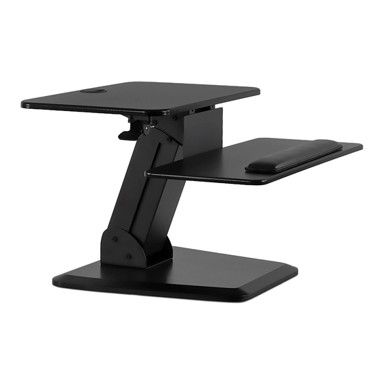
Summary of Contents for Mount-It! MI-7916
- Page 1 English Installation Instruction UNPACKING INSTRUCTIONS Carefully open the carton, remove contents and lay out on cardboard or other protective surface to avoid damage. Check package contents against the Supplied Parts List in the next page to assure that all components were received undamaged. Do not use damaged or defective parts.
- Page 2 Supplied Par ts List (1) Monitor Platform-a (1) Base-b (1) Keyboard Tray-c (1)Gas Spring Arm-d (1)L Plate-e (1)Wrist Pad-f (4)M6x12 Bolt-g (4)M6x12 Bolt-h (4)M6x28 Bolt-i (2)M6x35 Bolt-j (2)Spacer-k (4)M6 Washer-l (4)M6 Nut-m (2)Square Pad-n (4)Round Pad-o (1)Allen Key-p (1)Wrench-q...
- Page 3 Connecting L Plate to Keyboard Tray Step 1 Warning: Ensure screws are secured firmly. Attaching Square Pads to the Back of Keyboard Tray Step 2...
- Page 4 Step 3 Make Decision for the Lever Location Lever located on Left or Right? Connecting L Plate to Gas Spring Arm Step 4 Lever “L” plate can be connected to the Gas Spring Arm in two different positions. on left 1.
- Page 5 Connecting Gas Spring Arm to Monitor Platform Step 5 Warning: Ensure screws are secured firmly. Attaching Lever to the Back of Monitor Platform Step 6 Warning: Note: The lever can be installed Ensure screws are eigher on the right or the left secured firmly.
- Page 6 Connecting Base to Gas Spring Arm Step 7 Warning: Ensure screws are secured firmly. Attaching Round Pads to the Back of Base Step 8...
- Page 7 Attaching Wrist Pad to Keyboard Tray Step 9 Operating the Lever to Lift or Lower the WorkStation Step 10...
- Page 8 Adjusting the Tension of Workstation Step 11 • If the weight of the monitor(s) makes it difficult to lift the workstation, adjust the screw at the back of the gas spring arm counterclockwise. • If the workstation lowers too quickly, adjust the screw at the back of gas spring arm counterclockwise.


Need help?
Do you have a question about the MI-7916 and is the answer not in the manual?
Questions and answers