Table of Contents
Advertisement
Quick Links
Advertisement
Table of Contents

Subscribe to Our Youtube Channel
Related Manuals for IEI Technology uIBX-260-EHL Series


Summary of Contents for IEI Technology uIBX-260-EHL Series
- Page 1 MODEL: uIBX-260-EHL Series Fanless Embedded System with Intel® Celeron® J6412 Processor, On-board 8GB LPDDR4x, RS-232/422/485, Four USB 3.2, HDMI, Dual 2.5GbE, 12V DC and RoHS User Manual Page I Rev. 1.00 – April 19, 2023 [MODEL NAME]...
- Page 2 uIBX-260-EHL Revision Date Version Changes April 19, 2023 1.00 Initial release Page II [MODEL NAME]...
- Page 3 uIBX-260-EHL Copyright COPYRIGHT NOTICE The information in this document is subject to change without prior notice in order to improve reliability, design and function and does not represent a commitment on the part of the manufacturer. In no event will the manufacturer be liable for direct, indirect, special, incidental, or consequential damages arising out of the use or inability to use the product or documentation, even if advised of the possibility of such damages.
- Page 4 uIBX-260-EHL Manual Conventions WARNING Warnings appear where overlooked details may cause damage to the equipment or result in personal injury. Warnings should be taken seriously. CAUTION Cautionary messages should be heeded to help reduce the chance of losing data or damaging the product. NOTE These messages inform the reader of essential but non-critical information.
-
Page 5: Table Of Contents
uIBX-260-EHL Table of Content 1 INTRODUCTION ......................1 1.1 O ........................2 VERVIEW 1.2 F ........................3 EATURES 1.3 T ..................4 ECHNICAL PECIFICATIONS 1.4 F ......................6 RONT ANEL 1.5 R ....................... 7 ANEL 1.6 P ....................8 HYSICAL IMENSIONS 2 UNPACKING ......................... - Page 6 uIBX-260-EHL 3.9 P ................25 OWERING FF THE YSTEM 3.10 A ....................27 VAILABLE RIVERS 3.10.1 Driver Download ................... 28 4 SYSTEM MOTHERBOARD ..................30 4.1 O ....................... 31 VREVIEW 4.2 L ........................31 AYOUT 4.3 P ..............32 ERIPHERAL NTERFACE ONNECTORS 4.4 C...
- Page 7 uIBX-260-EHL 5.3.2 Trusted Computing ................... 62 5.3.3 IT5571 Super IO Configuration ............... 63 5.3.3.1 Serial Port 1 Configuration ............... 63 5.3.3.2 Serial Port 2 Configuration ............... 65 5.3.4 IT5571 H/W Monitor ..................66 5.3.5 Serial Port Console Redirection ..............67 5.3.5.1 Console Redirection Settings ..............
- Page 8 List of Figures Figure 1-1: uIBX-260-EHL Series ....................2 Figure 1-2: Front Panel ........................6 Figure 1-3: Top Panel ........................7 Figure 1-4: Physical Dimensions ....................8 Figure 3-1: Remove the Cover .....................15 Figure 3-2: HDD Installation ......................15 Figure 3-3: Inserting the M.2 Module into the Slot at an Angle..........16 Figure 3-4: Securing the M.2 Module ..................16...
- Page 9 uIBX-260-EHL Figure 4-6: Battery Connector Location ..................38 Figure 4-7: Buzzer Connector Location ..................39 Figure 4-8: RS-232 Serial Port Connector Location ..............40 Figure 4-9: SATA 6Gb/s Drive Connectors Location ..............41 Figure 4-10: Flash SPI ROM Connector Location ..............42 Figure 4-11: Flash EC ROM Connector Location ..............43 Figure 4-12: EC Debug Connector Location ................44 Figure 4-13: Internal USB 2.0 Connectors Locations ...............45 Figure 4-14: M.2 A-key Slot Location ..................46...
- Page 10 uIBX-260-EHL List of Tables Table 1-1: Technical Specifications ....................5 Table 3-1: RJ-45 Ethernet Connector LEDs ................24 Table 3-2: Power Connector Pinouts ..................24 Table 4-1: Peripheral Interface Connectors ................32 Table 4-2: Clear CMOS Pinouts ....................33 Table 4-3: AT/ATX Power Mode Switch Pinouts ................34 Table 4-4: DNX Mode setting Jumper Pinouts ................35 Table 4-5: Flash Descriptor Override Setting Jumper Pinouts ..........36 Table 4-6: Battery Connector Pinouts ..................38...
- Page 11 uIBX-260-EHL BIOS Menus BIOS Menu 1: Main (1/2) .......................55 BIOS Menu 2: Main (2/2) .......................55 BIOS Menu 3: Advanced ......................58 BIOS Menu 4: CPU Configuration (1/3)..................59 BIOS Menu 5: CPU Configuration (2/3)..................59 BIOS Menu 6: CPU Configuration (3/3)..................60 BIOS Menu 7: Trusted Computing ....................62 BIOS Menu 8: IT5571 Super IO Configuration ................63 BIOS Menu 9: Serial Port 1 Configuration Menu ...............63 BIOS Menu 10: Serial Port 2 Configuration Menu ..............65...
-
Page 13: Introduction
uIBX-260-EHL Chapter Introduction Page 1... -
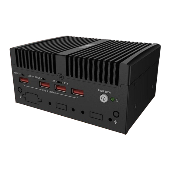
Page 14: Overview
1.1 Overview Figure 1-1: uIBX-260-EHL Series The uIBX-260-EHL series embedded system adopts Intel® Elkhart Lake processor with onboard 8GB LPDDR4x memory (up to 16GB), and equips multiple I/O, including one HDMI, two GbE LAN ports, four USB 3.2 Gen2 ports and one RS-232/422/485. One RS-232 and two USB 2.0 ports can be added through the reserved expansion interface. -
Page 15: Features
1.2 Features The uIBX-260-EHL Series features are listed below: ▪ Intel® Celeron® J6412 2.0GHz (up to 2.6GHz, quad-core, TDP 10W) ▪ Onboard 8GB LPDDR4x memory (up to 16GB) ▪ Four USB 3.2 Gen2 ▪ 2 x 2.5GbE ports ▪... -
Page 16: Technical Specifications
1.3 Technical Specifications The uIBX-260-EHL Series technical specifications are listed below Model Name uIBX-260-EHL Black Color 137 x 102.8 x 65.8 Dimension ( WxDxH)(mm) Chassis Fanless System Fan Extruded aluminum alloy Chassis Construction Intel® Celeron® J6412 2.0GHz (up to 2.6GHz, quad-core,... -
Page 17: Table 1-1: Technical Specifications
uIBX-260-EHL 12V@3.6 (Intel® Celeron® J6412 with 8GB DDR4 Memory) Power Consumption Wall Mount, VESA 75 Mounting -10 ~ 50° C with air flow (M.2), 10% ~ 95%, non-condensing Operating Temperature -20℃ ~70℃ with air flow (M.2), 10% ~ 90%, Storage Temperature non-condensing Half-sine wave shock 5G, 11ms, 100 shocks per axis (SSD) Operating Shock... -
Page 18: Front Panel
1.4 Front Panel The front panel of the uIBX-260-EHL Series has the following features. Figure 1-2: Front Panel Page 6... -
Page 19: Rear Panel
1.5 Rear Panel The rear panel of the uIBX-260-EHL Series is shown below. Figure 1-3: Top Panel Page 7... -
Page 20: Physical Dimensions
1.6 Physical Dimensions The physical dimensions of the uIBX-260-EHL Series are shown in Figure 1-4. Figure 1-4: Physical Dimensions Page 8... -
Page 21: Unpacking
uIBX-260-EHL Chapter Unpacking Page 9... -
Page 22: Anti-Static Precautions
Electrostatic discharge (ESD) can cause serious damage to electronic components, including the uIBX-260-EHL Series. Dry climates are especially susceptible to ESD. It is therefore critical that whenever the uIBX-260-EHL Series or any other electrical component is handled, the following anti-static precautions are strictly adhered to. -
Page 23: Unpacking Checklist
If some of the components listed in the checklist below are missing, please do not proceed with the installation. Contact the IEI reseller or vendor you purchased the uIBX-260-EHL Series from or contact an IEI sales representative directly. To contact an IEI sales representative, please send an email to sales@ieiworld.com. - Page 24 uIBX-260-EHL Quantity Item and Part Number Image Standard Power Cord The following table lists the optional items that can be purchased separately. Optional Wi-Fi module* (P/N: EMB-WIFI-KIT02I3-R10) Serial cable (P/N: 32205-008000-100-RS) USB cable (P/N: 32001-008600-200-RS) * Each Wi-Fi module needs two antennas and two RF cables to fully support Wi-Fi function.
-
Page 25: Installation
uIBX-260-EHL Chapter Installation Page 13... -
Page 26: Installation Precautions
Electric shock and personal injury might occur if the rear panel of the uIBX-260-EHL Series is opened while the power cord is still connected to an electrical outlet. -
Page 27: Storage Installation
uIBX-260-EHL Figure 3-1: Remove the Cover 3.3 Storage Installation The UIBX-260-EHL supports two types of storage, one M.2 M Key & one 2.5" HDD 3.3.1 2.5-inch SSD Installtion Put the hard disk on the back cover, lock the 4 screws, and connect the SATA cable (Figure 3-2). -
Page 28: Wi-Fi Module Installation (Optional)
uIBX-260-EHL Step 2: Remove the retention screw secured on the motherboard. Step 3: Line up the notch on the module with the notch on the slot. Slide the M.2 module into the socket at an angle of about 20º (Figure 3-3). Figure 3-3: Inserting the M.2 Module into the Slot at an Angle Step 4: Secure the M.2 module with the previously removed retention screw (Figure 3-4). -
Page 29: Figure 3-5: Inserting The Wlan Module
uIBX-260-EHL Step 3: Line up the notch on the WLAN module with the notch on the slot. Slide the WLAN module into the slot at an angle of about 20º (Figure 3-5). Figure 3-5: Inserting the WLAN Module Step 4: Secure the WLAN module with the retention screw previously removed (Figure 3-6). -
Page 30: Io Expansion Installation (Optional)
USB or COM port expansion is applicable only when 2.5-inch hard disk is not installed. The uIBX-260-EHL series provides USB and serial port expansion capabilities. I/O cables are available for purchase. To install the I/O ports, follow the steps below. -
Page 31: Figure 3-9: Rs-232 Cable Installation
uIBX-260-EHL Figure 3-9: RS-232 Cable Installation Step 3: Knock out the reserved holes on the chassis and secure the DB9 end of the serial cable to the panel. ( Figure 3-10 ) Figure 3-10: RS-232 DB9 Cable Installation Page 19... -
Page 32: Usb Installation
uIBX-260-EHL 3.5.2 USB installation Step 1: Locate the USB port connector. See Section 4.15 Step 2: Connect the USB cable to the USB connector on the mainboard. ( Figure 3-11 ) Figure 3-11: USB Cable Installation Step 3: Knock out the reserved holes on the chassis and Secure the USB end of the USB cable to the panel. -
Page 33: Back Cover Installation
uIBX-260-EHL 3.6 Back Cover Installation Install the back cover and fasten the 3 screws on the chassis. ( Figure 3-13 ) Figure 3-13: Back Cover Installation 3.7 Mounting the System To mount the embedded system onto a wall or some other surface using the two mounting brackets, please follow the steps below. -
Page 34: External Peripheral Interface Connectors
3.8 External Peripheral Interface Connectors The uIBX-260-EHL Series has the following connectors. Detailed descriptions of the connectors can be found in the subsections below. ▪ Ethernet ▪ Power button ▪ Power DC jack ▪ HDMI ▪ ▪ 3.8.1 HDMI Connector... -
Page 35: Lan Connectors
Chapter 1 Step 2: Align the connectors. Align the RJ-45 connector on the LAN cable with one of the RJ-45 connectors on the UIBX-260-EHL Series. Figure 3-16: LAN Connection Step 3: Insert the LAN cable RJ-45 connector. Once aligned, gently insert the LAN cable RJ-45 connector into the on-board RJ-45 connector The RJ-45 Ethernet connector has two status LEDs, one green and one yellow. -
Page 36: Power Connector
uIBX-260-EHL Blinking TX/RX activity Orange 2.5 Gbps connection Table 3-1: RJ-45 Ethernet Connector LEDs 3.8.3 Power Connector The power connector is a 2-pin DC jack connector on the rear panel that can directly connect to a power adapter. The supported power input voltage is 12 VDC. Description Table 3-2: Power Connector Pinouts Figure 3-18: Power Connector... -
Page 37: Powering On/Off The System
uIBX-260-EHL Figure 3-19: USB Connection 3.9 Powering On/Off the System WARNING: Make sure a power supply with the correct input voltage is being fed into the system. Incorrect voltages applied to the system may cause damage to the internal electronic components and may also cause injury to the user. -
Page 38: Figure 3-20: Power Input
uIBX-260-EHL Figure 3-20: Power Input ▪ Power on the system: press the power button for 1 seconds ▪ Power off the system: press the power button for 6 seconds Figure 3-21: Power Button& LED Page 26... -
Page 39: Available Drivers
M.2 SSD. Activity of SATA SSD/HDD will not trigger the LED. 3.10 Available Drivers All the drivers for the uIBX-260-EHL Series are available on IEI Resource Download Center (https://download.ieiworld.com). Type uIBX-260-EHL Series and press Enter to find all the relevant software, utilities, and documentation. -
Page 40: Driver Download
To download drivers from IEI Resource Download Center, follow the steps below. Step 1: Go to https://download.ieiworld.com . Type uIBX-260-EHL Series and press Enter. Step 2: All product-related software, utilities, and documentation will be listed. You can choose Driver to filter the result. - Page 41 uIBX-260-EHL NOTE: To install software from the downloaded ISO image file in Windows 10 (or later), double-click the ISO file to mount it as a virtual drive to view its content. Page 29...
-
Page 42: System Motherboard
uIBX-260-EHL Chapter System Motherboard Page 30... -
Page 43: Ovreview
uIBX-260-EHL 4.1 Ovreview The connectors and jumpers of the system motherboard are listed in the following sections. 4.2 Layout The following diagram shows the locations of the internal/external connectors and jumpers on the motherboard. Figure 4-1: Connector and Jumper Locations Page 31... -
Page 44: Peripheral Interface Connectors
uIBX-260-EHL 4.3 Peripheral Interface Connectors The table below lists all the connectors on the board. Connector Type Label Clear CMOS button Button J_CMOS1 AT/ATX power mode setting Switch J_ATX_AT1 Reset button Button RST1 Flash descriptor override setting jumper 3-pin header J_FLASH1 Battery connector 2-pin wafer... -
Page 45: Figure 4-2: Clear Cmos Location
uIBX-260-EHL Figure 4-2: Clear CMOS Location PIN NO. DESCRIPTION Keep CMOS Setup NC (default) (Normal Operation) Press button Clear CMOS Setup Table 4-2: Clear CMOS Pinouts Page 33... -
Page 46: At/Atx Power Mode Setting
uIBX-260-EHL 4.5 AT/ATX Power Mode Setting CN Label: J_ATX_AT1 CN Type: 3-pin switch CN Location: See Figure 4-3 CN Pinouts: See Table 4-3 The AT/ATX power mode selection is made through the AT/ATX power mode switch which is shown in Figure 4-3. Figure 4-3: AT/ATX Power Mode Switch Locations PIN NO. -
Page 47: Reset Button Connector
uIBX-260-EHL 4.6 Reset Button Connector CN Label: RST1 CN Type: Button CN Location: See Figure 4-4 CN Pinouts: See Table 4-4 Figure 4-4: Reset Button Connector Location PIN NO. DESCRIPTION NC (default) Press button Reset Button Table 4-4: DNX Mode setting Jumper Pinouts Page 35... -
Page 48: Flash Descriptor Override Setting Jumper
uIBX-260-EHL 4.7 Flash Descriptor Override Setting Jumper CN Label: J_FLASH1 CN Type: 3-pin header,P=2.00mm CN Location: See Figure 4-5 CN Pinouts: See Table 4-5 The J_FLASH1 connector is used for Flash Descriptor Security Overide . Figure 4-5: Flash Descriptor Override Setting Jumper Locations PIN NO. -
Page 49: Rtc Battery Connector
Dispose of used batteries according to instructions and local regulations. NOTE: It is recommended to attach the RTC battery onto the system chassis in which the uIBX-260-EHL Series is installed. CN Label: BAT2 CN Type: 2-pin wafer, p=1.25 mm... -
Page 50: Buzzer Connector
uIBX-260-EHL Figure 4-6: Battery Connector Location Description VBATT Table 4-6: Battery Connector Pinouts 4.9 Buzzer Connector CN Label: CN Type: 2-pin wafer, p=1.25 mm CN Location: See Figure 4-7 CN Pinouts: See Table 4-7 The buzzer conector is connected with the buzzer to give a beep warning when the motherboard goes wrong. -
Page 51: Figure 4-7: Buzzer Connector Location
uIBX-260-EHL Figure 4-7: Buzzer Connector Location Description PC_BEEP Table 4-7: Buzzer Connector Pinouts Page 39... -
Page 52: Serial Port Connector
uIBX-260-EHL 4.10 RS-232 Serial Port Connector CN Label: COM2 CN Type: 9-pin wafer, p=1.25 mm CN Location: See Figure 4-8 CN Pinouts: See Table 4-8 The serial connector provides RS-232 connection. Figure 4-8: RS-232 Serial Port Connector Location PIN NO. DESCRIPTION PIN NO. -
Page 53: Sata 6Gb/S Drive Connector
uIBX-260-EHL 4.11 SATA 6Gb/s Drive Connector CN Label: SATA0 CN Type: 20-pin iSATA connector CN Location: See Figure 4-9 CN Pinouts: See Table 4-9 The SATA 6Gb/s drive connector is connected to a SATA 6Gb/s drive. The SATA 6Gb/s drive transfers data at speeds as high as 6Gb/s. Figure 4-9: SATA 6Gb/s Drive Connectors Location PIN NO. -
Page 54: Flash Spi Rom Connector
uIBX-260-EHL 4.12 Flash SPI ROM Connector CN Label: JBIOS1 CN Type: 6-pin wafer, p=1.25 mm CN Location: See Figure 4-10 CN Pinouts: See Table 4-10 The 6-pin Flash SPI ROM connector is used to flash the BIOS. Figure 4-10: Flash SPI ROM Connector Location Description +3.3V SPI_CS#... -
Page 55: Flash Ec Rom Connector
uIBX-260-EHL 4.13 Flash EC ROM Connector CN Label: EC_FLASH1 CN Type: 4-pin header, p=1.25 mm CN Location: See Figure 4-11 CN Pinouts: See Table 4-11 The 4-pin Flash EC ROM connector is used to flash the EC internal ROM. Figure 4-11: Flash EC ROM Connector Location Description Description EC_FLASH_DAT... -
Page 56: Internal Usb 2.0 Connectors
uIBX-260-EHL Figure 4-12: EC Debug Connector Location Description Description SMCLK1_EC SMDAT1_EC PLT_RST_N Table 4-12: EC Debug Connector Pinouts 4.15 Internal USB 2.0 Connectors CN Label: USB2_CN1 CN Type: 8-pin header, p=2.00 mm CN Location: See Figure 4-13 CN Pinouts: See Table 4-13 Each USB connector provides two USB 2.0 ports by dual-port USB cable. -
Page 57: Figure 4-13: Internal Usb 2.0 Connectors Locations
uIBX-260-EHL Figure 4-13: Internal USB 2.0 Connectors Locations PIN NO. DESCRIPTION PIN NO. DESCRIPTION USB DATA- USB DATA+ USB DATA+ USB DATA- Table 4-13: Internal USB 2.0 Connectors Pinouts Page 45... -
Page 58: A-Key Slot
uIBX-260-EHL 4.16 M.2 A-key Slot CN Label: M2_A_LEY CN Type: M.2 A-key slot CN Location: See Figure 4-14 CN Pinouts: See Table 4-14 The M.2 slot is keyed in the A position and accepts 2230 size of M.2 modules. The M.2 slot supports PCIe Gen3 x1 and USB 2.0 signals. -
Page 59: Table 4-14: M.2 A-Key Slot Pinouts
uIBX-260-EHL Description Description PCIE_TX2+ PCIE_TX2- PCIE_RX2+ PCIE_RX2- CLK_PCIE2+ CLK_PCIE2- PMC_SUS_CLK WLAN_PERST# +V3.3A_WLAN +V3.3A_WLAN +V3.3A_WLAN +V3.3A +V3.3A Table 4-14: M.2 A-Key Slot Pinouts Page 47... -
Page 60: M-Key Slot
uIBX-260-EHL 4.17 M.2 M-key Slot CN Label: M2_M1 CN Type: M.2 M-key slot CN Location: Figure 4-15 791H CN Pinouts: See Table 4-15 The M.2 M key (2280) slot with PCIe Gen3 x2 supports NVMe storage. Figure 4-15: M.2 M-key Slot Location PIN NO. -
Page 61: Table 4-15: M.2 B-Key Slot Pinouts
uIBX-260-EHL PCIE_RXN1 PCIE_RXP1 PCIE_TXN1 PCIE_TXP1 DEVSLP PCIE_RXN0 PCIE_RXP0 PCIE_TXN0 PCIE_TXP0 PERST# CLKREQ# REFCLKN PEWAKE REFCLKP Module Key Module Key Module Key Module Key Module Key Module Key Module Key Module Key SUSCLK PEDET +3.3V +3.3V +3.3V Table 4-15: M.2 B-key Slot Pinouts Page 49... -
Page 62: Bios
uIBX-260-EHL Chapter BIOS Page 50... -
Page 63: Introduction
uIBX-260-EHL 5.1 Introduction The BIOS is programmed onto the BIOS chip. The BIOS setup program allows changes to certain system settings. This chapter outlines the options that can be changed. NOTE: Some of the BIOS options may vary throughout the life cycle of the product and are subject to change without prior notice. -
Page 64: Using Setup
uIBX-260-EHL 5.1.2 Using Setup The BIOS Setup menu can be navigated by using a keyboard or a touchscreen. 5.1.2.1 Keyboard Navigation For keyboard navigation, use the navigation keys shown in Figure 5-2. Function Up arrow Move to previous item Down arrow Move to next item Left arrow Move to the item on the left hand side... -
Page 65: Touch Navigation
uIBX-260-EHL 5.1.2.2 Touch Navigation For touchscreen navigation, use the on-screen navigation keys shown below. On-screen Button Function Previous Values Load the last value you set. Optimized Defaults Load the factory default values in order to achieve the best performance. Back Return to the previous menu. -
Page 66: Unable To Reboot After Configuration Changes
uIBX-260-EHL 5.1.4 Unable to Reboot after Configuration Changes If the computer cannot boot after changes to the system configuration is made, CMOS defaults. Use the clear CMOS button described in Chapter 4. 5.1.5 BIOS Menu Bar The menu bar on top of the BIOS screen has the following main items: Main –... -
Page 67: Main
uIBX-260-EHL 5.2 Main The Main BIOS menu (BIOS Menu 1 & BIOS Menu 2) appears when the BIOS Setup program is entered. The Main menu gives an overview of the basic system information. BIOS Menu 1: Main (1/2) BIOS Menu 2: Main (2/2) ➔... - Page 68 uIBX-260-EHL BIOS Vendor: Installed BIOS vendor Core Version: Current BIOS version Compliancy: Current UEFI & PI version Project Version: the board version Build Date and Time: Date the current BIOS version was made EC Version: Current EC version Access Level: Administrator ➔...
- Page 69 uIBX-260-EHL ➔ System Date [xx/xx/xx] Use the System Date option to set the system date. Manually enter the day, month and year. ➔ System Time [xx:xx:xx] Use the System Time option to set the system time. Manually enter the hours, minutes and seconds.
-
Page 70: Advanced
uIBX-260-EHL 5.3 Advanced Use the Advanced menu (BIOS Menu 3) to configure the CPU and peripheral devices through the following sub-menus: WARNING! Setting the wrong values in the sections below may cause the system to malfunction. Make sure that the settings made are compatible with the hardware. -
Page 71: Cpu Configuration
uIBX-260-EHL 5.3.1 CPU Configuration Use the CPU Configuration menu (BIOS Menu 4 &BIOS Menu 5 & BIOS Menu 6) to view detailed CPU specifications or enable the Intel Virtualization Technology. BIOS Menu 4: CPU Configuration (1/3) BIOS Menu 5: CPU Configuration (2/3) Page 59... - Page 72 uIBX-260-EHL BIOS Menu 6: CPU Configuration (3/3) ➔ Intel (VMX) Virtualization Technology [Disabled] Use the Intel (VMX) Virtualization Technology option to enable or disable virtualization on the system. When combined with third party software, Intel® Virtualization technology allows several OSs to run on the same system at the same time. ➔...
- Page 73 uIBX-260-EHL ➔ Power Limit 1 Use the Power Limit 1 to set Power Limit in Milli Watts. BIOS will round to the nearest 1/8W when programming. 0 = no custom override. For 12.50W, enter 12500. Overclocking SKU: Value must be between Max and Min Power Limits. Other SKUs: This value must be between Min Power limit and TDP Limit.
-
Page 74: Trusted Computing
uIBX-260-EHL 5.3.2 Trusted Computing The Trusted Computing menu (BIOS Menu 7) to configure settings related to the Trusted Computing Group (TCG) Trusted Platform Module (TPM) BIOS Menu 7: Trusted Computing ➔ Security Device Support [Enable] Use the Security Device Support option to configure support for the Security Device. ➔... -
Page 75: It5571 Super Io Configuration
uIBX-260-EHL 5.3.3 IT5571 Super IO Configuration Use the IT5571 Super IO Configuration menu (BIOS Menu 8) to set or change the configurations for the serial ports. BIOS Menu 8 IT5571 Super IO Configuration 5.3.3.1 Serial Port 1 Configuration Use the Serial Port 1 Configuration menu (BIOS Menu 9) to configure the serial port n. BIOS Menu 9: Serial Port 1 Configuration Menu Page 63... - Page 76 uIBX-260-EHL ➔ Serial Port [Enabled] Use the Serial Port option to enable or disable the serial port. ➔ Disabled Disable the serial port ➔ Enabled Enable the serial port EFAULT ➔ Device Settings The Device Settings option shows the serial port IO port address and interrupt address. ➔...
-
Page 77: Serial Port 2 Configuration
uIBX-260-EHL 5.3.3.2 Serial Port 2 Configuration Use the Serial Port 2 Configuration menu (BIOS Menu 10 )to configure the serial port n. BIOS Menu 10: Serial Port 2 Configuration Menu ➔ Serial Port [Enabled] Use the Serial Port option to enable or disable the serial port. ➔... -
Page 78: It5571 H/W Monitor
uIBX-260-EHL 5.3.4 IT5571 H/W Monitor The IT5571 H/W Monitor menu (BIOS Menu 11) shows the state of H/W real-time operating temperature, fan speeds and system voltages BIOS Menu 11: IT5571 H/W Monitor ➔ PC Health Status The following system parameters and values are shown. The system parameters that are monitored are: ▪... -
Page 79: Serial Port Console Redirection
uIBX-260-EHL 5.3.5 Serial Port Console Redirection The Serial Port Console Redirection menu (BIOS Menu 12) allows the console redirection options to be configured. Console Redirection allows users to maintain a system remotely by re-directing keyboard input and text output through the serial port. BIOS Menu 12:Serial Port Console Redirection ➔... -
Page 80: Bios Menu 13: Com Console Redirection Settings
uIBX-260-EHL BIOS Menu 13: COM Console Redirection Settings Terminal Type [ANSI] ➔ Use the Terminal Type option to specify the remote terminal type. ➔ VT100 The target terminal type is VT100 ➔ VT100+ The target terminal type is VT100+ ➔ VT-UTF8 The target terminal type is VT-UTF8 ➔... - Page 81 uIBX-260-EHL ➔ 115200 Sets the serial port transmission speed at 115200. EFAULT ➔ Data Bits [8] Use the Data Bits option to specify the number of data bits. ➔ Sets the data bits at 7. ➔ Sets the data bits at 8. EFAULT ➔...
-
Page 82: Nvme Configuration
uIBX-260-EHL 5.3.6 NVMe Configuration Use the NVMe Configuration (BIOS Menu 14) menu to display the NVMe controller and device information. BIOS Menu 14: NVMe configuration Page 70... -
Page 83: Sdio Configuration
uIBX-260-EHL 5.3.7 SDIO Configuration Use the SDIO Configuration (BIOS Menu 15) menu to display. BIOS Menu 15: SDIO Configuration SDIO Access Mode Select: ➔ Auto Access the SD device in DMA mode if the controller supports it. Otherwise, this will access the SD device in PIO mode. -
Page 84: Chipset
uIBX-260-EHL 5.4 Chipset Use the Chipset menu (BIOS Menu 16) to access the PCH IO and System Agent (SA) configuration menus. WARNING! Setting the wrong values for the Chipset BIOS selections in the Chipset BIOS menu may cause the system to malfunction. BIOS Menu 16: Chipset Page 72... -
Page 85: System Agent (Sa) Configuration
uIBX-260-EHL 5.4.1 System Agent (SA) Configuration Use the System Agent (SA) Configuration menu (BIOS Menu 17) to configure the System Agent (SA) parameters. BIOS Menu 17: System Agent (SA) Configuration ➔ VT-d [Enabled] Use the VT-d option to enable or disable the VT-d capability. ➔... -
Page 86: Memory Configuration
uIBX-260-EHL 5.4.1.1 Memory Configuration Use the Memory Configuration submenu (BIOS Menu 18) to view memory information. BIOS Menu 18: Memory Configuration Page 74... -
Page 87: Graphics Configuration
uIBX-260-EHL 5.4.1.2 Graphics Configuration Use the Graphics Configuration (BIOS Menu 19) menu to configure the video device connected to the system. BIOS Menu 19: Graphics Configuration ➔ DVMT Pre-Allocated [32M] Use the DVMT Pre-Allocated option to set the amount of system memory allocated to the integrated graphics processor when the system boots. -
Page 88: Pch-Io Configuration
uIBX-260-EHL 5.4.2 PCH-IO Configuration Use the PCH-IO Configuration menu (BIOS Menu 20 &BIOS Menu 21) to configure the PCH parameters. BIOS Menu 20: PCH-IO Configuration(1/2) BIOS Menu 21: PCH-IO Configuration (2/2) Page 76... - Page 89 uIBX-260-EHL ➔ Auto Power Button Function [Enabled(AT)] Use the Auto Power Button Function BIOS option to show the power mode state. Use the J_ATX_AT1 to switch the AT/ATX power mode. ➔ Enabled (AT) The system power mode is AT. ➔ Disabled (ATX) The system power mode is ATX.
-
Page 90: Figure 5-4: Bios Options And Configured Usb Ports
uIBX-260-EHL ➔ USB Power SW2 [+5V DUAL] Use the USB Power SW2 BIOS option to configure the USB power source for the corresponding USB connectors (Figure 5-4). ➔ +5V DUAL Sets the USB power source to +5V dual EFAULT ➔ Sets the USB power source to +5V BIOS Options Configured USB Ports... -
Page 91: Pci Express Configuration
uIBX-260-EHL 5.4.2.1 PCI Express Configuration Use the PCI Express Configuration submenu (BIOS Menu 22 & BIOS Menu 23) to configure the PCI Express slots. BIOS Menu 22: PCI Express Configuration BIOS Menu 23: PCIe Slot Configuration Submenu Page 79... - Page 92 uIBX-260-EHL ➔ 2.5Gbe LAN1 / 2.5Gbe LAN2 / M.2_A1 / M.2_M2 [Enabled] Use the 2.5Gbe LAN1 / 2.5Gbe LAN2 / M.2_A1 / M.2_M2 option to enable or disable the corresponding PCI Express port. ➔ Disabled Disable the PCI Express port. EFAULT ➔...
-
Page 93: Sata Configuration
uIBX-260-EHL 5.4.2.2 SATA Configuration Use the SATA Configuration menu (BIOS Menu 24) to change and/or set the configuration of the SATA devices installed in the system. BIOS Menu 24: SATA Configuration ➔ SATA Mode Selection [ACHI] Use the SATA Mode Selection option to configure the SATA controller(s) operate. ➔... -
Page 94: Hd Audio Configuration
uIBX-260-EHL 5.4.2.3 HD Audio Configuration Use the HD Audio Configuration menu (BIOS Menu 25) to configure the PCH Azalia settings. BIOS Menu 25: HD Audio Configuration ➔ HD Audio [Auto] Use the HD Audio option to enable or disable the High Definition Audio controller. ➔... -
Page 95: Security
uIBX-260-EHL 5.5 Security Use the Security menu (BIOS Menu 26) to set system and user passwords. BIOS Menu 26: Security ➔ Administrator Password Use the Administrator Password to set or change a administrator password. ➔ User Password Use the User Password to set or change a user password. Page 83... -
Page 96: Boot
uIBX-260-EHL 5.6 Boot Use the Boot menu (BIOS Menu 27) to configure system boot options. BIOS Menu 27: Boot 5.6.1 Boot Configuration ➔ Quiet Boot [Enabled] Use the Quiet Boot BIOS option to select the screen display when the system boots. ➔... -
Page 97: Boot Option Priorities
uIBX-260-EHL ➔ Option ROM Messages [Force BIOS] Use the Option ROM Messages option to set the Option ROM display mode. ➔ Force Sets display mode to force BIOS. EFAULT BIOS ➔ Keep Sets display mode to current. Current 5.6.2 Boot Option Priorities Use the Boot Option # N to choose the system boots from the peripherals you selected The following Boot Options are listed as an example. -
Page 98: Save & Exit
uIBX-260-EHL 5.7 Save & Exit Use the Save & Exit menu (BIOS Menu 28) to load default BIOS values, optimal failsafe values and to save configuration changes. BIOS Menu 28: Save & Exit ➔ Save Changes and Reset Use the Save Changes and Reset option to save the changes made to the BIOS options and reset the system. - Page 99 uIBX-260-EHL ➔ Restore User Defaults Use the Restore User Defaults option to restore the user defaults to all the setup options. Page 87...
- Page 100 uIBX-260-EHL Appendix Regulatory Compliance Page 88...
- Page 101 uIBX-260-EHL DECLARATION OF CONFORMITY This equipment has been tested and found to comply with specifications for CE marking. If the user modifies and/or installs other devices in the equipment, the CE conformity declaration may no longer apply. FCC WARNING This equipment complies with Part 15 of the FCC Rules. Operation is subject to the following two conditions: ◼...
- Page 102 uIBX-260-EHL Appendix Product Disposal Page 90...
- Page 103 uIBX-260-EHL CAUTION: Risk of explosion if battery is replaced by an incorrect type. Only certified engineers should replace the on-board battery. Dispose of used batteries according to instructions and local regulations. Outside the European Union–If you wish to dispose of used electrical and electronic products outside the European Union, please contact your local authority so as to comply with the correct disposal method.
- Page 104 uIBX-260-EHL Appendix Error Beep Code Page 92...
- Page 105 uIBX-260-EHL C.1 PEI Beep Codes Number of Beeps Description Memory not Installed Memory was installed twice (InstallPeiMemory routine in PEI Core called twice) Recovery started DXEIPL was not found DXE Core Firmware Volume was not found Recovery failed S3 Resume failed Reset PPI is not available C.2 DXE Beep Codes Number of Beeps...
- Page 106 uIBX-260-EHL Appendix Hazardous Materials Disclosure Page 94...
- Page 107 uIBX-260-EHL D.1 RoHS II Directive (2015/863/EU) The details provided in this appendix are to ensure that the product is compliant with the RoHS II Directive (2015/863/EU). The table below acknowledges the presences of small quantities of certain substances in the product, and is applicable to RoHS II Directive (2015/863/EU).
- Page 108 uIBX-260-EHL D.2 China RoHS 此附件旨在确保本产品符合中国 RoHS 标准。以下表格标示此产品中某有毒物质的含量符 合中国 RoHS 标准规定的限量要求。 本产品上会附有”环境友好使用期限”的标签,此期限是估算这些物质”不会有泄漏或突变”的 年限。本产品可能包含有较短的环境友好使用期限的可替换元件,像是电池或灯管,这些元 件将会单独标示出来。 部件名称 有毒有害物质或元素 壳体 印刷电路板 金属螺帽 电缆组装 风扇组装 电力供应组装 电池 O: 表示该有毒有害物质在该部件所有物质材料中的含量均在 SJ/T11364-2014 與 GB/T26572-2011 标准规定的限量要求以下。 X: 表示该有毒有害物质至少在该部件的某一均质材料中的含量超出 SJ/T11364-2014 與 GB/T26572-2011 标准规定的限量要求。 Page 96...
Need help?
Do you have a question about the uIBX-260-EHL Series and is the answer not in the manual?
Questions and answers