Table of Contents
Advertisement
Quick Links
Advertisement
Table of Contents

Related Manuals for IEI Technology DRPC-242-ADL-P Series


Summary of Contents for IEI Technology DRPC-242-ADL-P Series
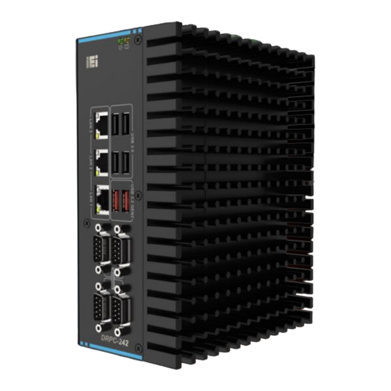
- Page 1 DRPC-242-ADL-P MODEL: DRPC-242-ADL-P Series Embedded system supports 12th Gen Intel® Alder Lake P on-board processor, dual-channel DDR4 SO-DIMMs, HDMI/DP, 3 x 2.5GbE LAN, 4 x COM, 6 x USB, 12~24V DC, RoHS User Manual Page I Rev. 1.00 – September 7, 2023...
- Page 2 DRPC-242-ADL-P Revision Date Version Changes Sept. 7, 2023 1.00 Initial release Page II [MODEL NAME]...
- Page 3 DRPC-242-ADL-P Copyright COPYRIGHT NOTICE The information in this document is subject to change without prior notice in order to improve reliability, design and function and does not represent a commitment on the part of the manufacturer. In no event will the manufacturer be liable for direct, indirect, special, incidental, or consequential damages arising out of the use or inability to use the product or documentation, even if advised of the possibility of such damages.
- Page 4 DRPC-242-ADL-P Manual Conventions WARNING Warnings appear where overlooked details may cause damage to the equipment or result in personal injury. Warnings should be taken seriously. CAUTION Cautionary messages should be heeded to help reduce the chance of losing data or damaging the product. NOTE These messages inform the reader of essential but non-critical information.
-
Page 5: Table Of Contents
DRPC-242-ADL-P Table of Content 1 INTRODUCTION ......................1 1.1 O ........................2 VERVIEW 1.2 F ........................2 EATURES 1.3 M ....................3 ODEL ARIATIONS 1.4 T ..................3 ECHNICAL PECIFICATIONS 1.5 F ......................6 RONT ANEL 1.6 T ......................... 7 ANEL 1.7 R ..................... - Page 6 DRPC-242-ADL-P 3.11 M ..............29 OUNTING RACKETS NSTALLATION 3.11.1 DIN-Rail Installation..................29 3.11.2 Wall Mounting Installation ................31 3.12 E ..........33 XTERNAL ERIPHERAL NTERFACE ONNECTORS 3.12.1 HDMI/ DP Connector ..................33 3.12.2 LAN Connectors ..................... 33 3.13 P ....................35 OWER ONNECTOR 3.14 A...
- Page 7 DRPC-242-ADL-P 4.2.18 Flash EC ROM Connector ................67 4.2.19 EC Debug Connector ..................68 4.2.20 PMBUS Connector ..................69 4.3 E ......... 70 XTERNAL ERIPHERAL NTERFACE ONNECTOR ANEL 4.3.1 Power Switch ....................70 4.3.2 Reset Button Connector ................... 72 4.3.3 HDMI Connectors .................... 73 4.3.4 System Fan Connector ..................
- Page 8 DRPC-242-ADL-P 5.3.7 Serial Port Console Redirection ..............106 5.3.7.1 Console Redirection Settings ..............108 5.3.8 NVMe Configuration ..................111 5.4 C ........................112 HIPSET 5.4.1 System Agent (SA) Configuration ..............113 5.4.1.1 Memory Configuration ................114 5.4.1.2 Graphics Configuration ................115 5.4.1.3 VMD setup menu (RAID Mode) .............
- Page 9 DRPC-242-ADL-P List of Figures Figure 1-1: DRPC-242-ADL-P Series ..................... 2 Figure 1-2: Front Panel ........................6 Figure 1-3: back Panel ........................7 Figure 1-4: DRPC-242-ADL-P Right Side Panel ................8 Figure 1-5: Physical Dimensions ....................9 Figure 1-6: DRPC-242-ADL-P Dimensions .................10 Figure 3-1: Remove the Cover .....................18...
- Page 10 DRPC-242-ADL-P Figure 3-25: LAN Connection ......................34 Figure 3-26: RJ-45 Ethernet Connector ..................34 Figure 3-27: Power Connector ....................35 Figure 3-28:Power & HDD LED ....................36 Figure 3-29: ME Override Setting Jumper Locations ..............39 Figure 3-30: Clear CMOS Location .....................41 Figure 3-31: AT/ATX Power Mode Setting Location ..............42 Figure 4-1: Connector and Jumper Locations ................44 Figure 4-2: System Motherboard (Rear) ..................45 Figure 4-3: Battery Connector Location ..................47...
- Page 11 DRPC-242-ADL-P Figure 5-1: BIOS Starting Menu ....................78 Figure 5-2: BIOS Navigation Keys ....................79 Figure 5-3: BIOS On-screen Navigation Keys ................80 Page XI [MODEL NAME]...
- Page 12 DRPC-242-ADL-P List of Tables Table 1-1: Model Variations of DRPC-242 ..................3 Table 1-2: Technical Specifications ....................5 Table 3-1: RJ-45 Ethernet Connector LEDs ................34 Table 3-2: ME Override Setting Jumper Pinouts ...............40 Table 3-3: Clear CMOS Pinouts ....................41 Table 4-1: Internal Peripheral Connectors .................46 Table 4-2: Battery Connector Pinouts ..................47 Table 4-3: SIM Card Connector Pinouts ..................48 Table 4-4: Internal USB 2.0 Connectors Pinouts ...............50...
- Page 13 DRPC-242-ADL-P Table 5-1: BIOS Options and Configured USB Ports ..............123 Page XIII [MODEL NAME]...
- Page 14 DRPC-242-ADL-P BIOS Menus BIOS Menu 1: Main (1/2) .......................82 BIOS Menu 2: Main (2/2) .......................82 BIOS Menu 3: Advanced (1/2) ......................86 BIOS Menu 4: Advanced (2/2) ......................86 BIOS Menu 5: CPU Configuration (1/3)..................87 BIOS Menu 6: CPU Configuration (2/3)..................87 BIOS Menu 7: CPU Configuration (3/3)..................88 BIOS Menu 8:AMT Configuration ....................91 BIOS Menu 9: Trusted Computing ....................92 BIOS Menu 10: RTC Wake Settings ....................93...
- Page 15 DRPC-242-ADL-P BIOS Menu 31: PEG Port Configuration ...................117 BIOS Menu 32: M2_M1 .......................118 BIOS Menu 33: PCIEX4_1 Slot ....................119 BIOS Menu 34: PCI-IO Configuration (1/2) ................121 BIOS Menu 35: PCI-IO Configuration (2/2) ................121 BIOS Menu 36: PCI Express Configuration ................124 BIOS Menu 37: PCI Express Root Port Settings ..............125 BIOS Menu 38: SATA Configuration ..................127 BIOS Menu 39: HD Audio Configuration ..................128...
-
Page 17: Introduction
DRPC-242-ADL-P Chapter Introduction Page 1... -
Page 18: Overview
DDR4 SO-DIMM memory (8GB pre-installed). It is designed for harsh environment applications, and supports DIN rail mounting method. The DRPC-242-ADL-P Series accepts a wide range of DC power input (12V ~ 28V), allowing it to be powered anywhere. It is equipped with two USB 3.2 Gen2 (10Gb/s), four USB 2.0, three 2.5GbE, two isolation RS-232 ports, two isolation RS-422/485 ports, one... -
Page 19: Model Variations
Intel® Core™ i5-1240P (up to 4.4GHz, 12-core, 28W DRPC-242-ADL-P-i5CS TDP) Intel® Core™ i7-1260P (up to 4.7GHz, 12-core, 28W DRPC-242-ADL-P-i7CS TDP) Table 1-1: Model Variations of DRPC-242 1.4 Technical Specifications The DRPC-242-ADL-P Series technical specifications are listed in (Table 1-2) Page 3... - Page 20 DRPC-242-ADL-P Model name DRPC-242-ADL-P-CCS DRPC-242-ADL-P-i3CS DRPC-242-ADL-P-i5CS DRPC-242-ADL-P-i7CS Dimensions 81 x 150 x190 System fan Fanless (Fan optional) Chassis Chassis Extruded Aluminum alloys Construction ™ ™ ™ ® ® ® ® ® Intel Celeron 7305 Intel Core i3-1220P Intel Core i5-1240P Intel Core i7-1260P...
-
Page 21: Table 1-2: Technical Specifications
DRPC-242-ADL-P 12V@4.46A (Intel ® Core™ i7-1260P with DDR4 8G Memory) Consumption Mounting DIN-rail Operating -20° C ~ 60° C with air flow (SSD) Temp Storage Temp -40° C ~ 85° C Humidity 10% ~ 95%, non-condensing Reliability Operating Half-sine wave shock 5G, 11ms, 3 shocks per axis (SSD) shock Operating 10-500 Hz,1.04 Grms, random, 1 hr/axis (SSD) -
Page 22: Front Panel
DRPC-242-ADL-P 1.5 Front Panel The front panel of the DRPC-242-ADL-P Series has the following features. Figure 1-2: Front Panel Page 6... -
Page 23: Top Panel
DRPC-242-ADL-P 1.6 Top Panel The top panel of the DRPC-242-ADL-P Series is shown below. Figure 1-3: back Panel Page 7... -
Page 24: Right Side Panel
DRPC-242-ADL-P 1.7 Right Side Panel The DRPC-242-ADL-P Series' right side panel contains one system fan connector. Figure 1-4: DRPC-242-ADL-P Right Side Panel Page 8... -
Page 25: Physical Dimensions
DRPC-242-ADL-P 1.8 Physical Dimensions The physical dimensions of the DRPC-242-ADL-P Series are shown in (Figure 1-5). Figure 1-5: Physical Dimensions Page 9... -
Page 26: Figure 1-6: Drpc-242-Adl-P Dimensions
DRPC-242-ADL-P With expansion layer Dimensions Figure 1-6: DRPC-242-ADL-P Dimensions Page 10... -
Page 27: Unpacking
DRPC-242-ADL-P Chapter Unpacking Page 11... -
Page 28: Anti-Static Precautions
DRPC-242-ADL-P Series and severe injury to the user. Electrostatic discharge (ESD) can cause serious damage to electronic components, including the DRPC-242-ADL-P Series. Dry climates are especially susceptible to ESD. It is therefore critical that whenever the DRPC-242-ADL-P Series or any other electrical component is handled, the following anti-static precautions are strictly adhered to. -
Page 29: Unpacking Checklist
If some of the components listed in the checklist below are missing, please do not proceed with the installation. Contact the IEI reseller or vendor you purchased the DRPC-242-ADL-P Series from or contact an IEI sales representative directly. To contact an IEI sales representative, please send an email to sales@ieiworld.com. - Page 30 DRPC-242-ADL-P The following table lists the optional items that can be purchased separately. Optional Wi-Fi module (P/N: EMB-WIFI-KIT02I3-R10) DIO cable (P/N: 32031-000600-100-RS) European Power Cord (P/N: 32702-000200-100-RS) Serial cable (P/N: 32205-005401-100-RS) Power adapter (120W) (P/N: 63040-010120-300-RS) Power adapter (180W) (P/N: 63040-010180-200-RS) Page 14...
- Page 31 DRPC-242-ADL-P Optional Power cord (P/N: 32702-000200-100-RS) Wall mount brackets (P/N:41020-0578C2-00-HF*2) 1-slot expansion chassis with riser card (P/N: TXC-DRPC-240-1S-R10) External fan module (P/N: SF-DRPC-240-R10) * Each Wi-Fi module needs two antennas and two RF cables to fully support Wi-Fi function. Page 15...
-
Page 32: Installation
DRPC-242-ADL-P Chapter Installation Page 16... -
Page 33: Installation Precautions
Electric shock and personal injury might occur if the rear panel of the DRPC-242-ADL-P Series is opened while the power cord is still connected to an electrical outlet. -
Page 34: Back Cover Removal
DRPC-242-ADL-P 3.2 Back Cover Removal Before installing or maintaining the internal components, the cover must be removed from the DRPC-242-ADL-P Series. Follow the steps below to complete the task. Step 1: Loosen the 5 screws on the top cover. Step 2: Take off the back cover (Figure 3-1). -
Page 35: Memory Installation
DRPC-242-ADL-P Figure 3-2: Removing the HDD Bracket 3.4 Memory Installation The DRPC-242-ADL-P Series is pre-installed with an 8GB memory module. Users can add or replace memory with different capacity by themselves, the installation procedures are described below. Step 1: Open the two handles of the memory slot. -
Page 36: Storage Installation
Figure 3-3: Memory Installation 3.5 Storage Installation The DRPC-242-ADL-P Series supports two types of storage, one M.2 M Key & one 2.5" SSD. Before installing a M.2 SSD or 2.5" SSD/HDD, please follow the steps described in Section 3.3 to remove the HDD bracket. -
Page 37: Ssd Installation
DRPC-242-ADL-P Figure 3-4: HDD Installation 3.5.2 M.2 SSD Installation To install an M.2 B Key NVME, please follow the steps below. Step 1: Locate the M.2 module slot. See section 4.2.6 Step 2: Remove the retention screw secured on the motherboard. Step 3: Line up the notch on the module with the notch on the slot. -
Page 38: Wi-Fi Module Installation (Optional)
DRPC-242-ADL-P Figure 3-6: Securing the M.2 Module 3.6 Wi-Fi Module Installation (Optional) The Wi-Fi module is an optional accessory. You can purchase it from IEI or other providers. Note that you have to purchase Wi-Fi module, internal antenna and external antenna. -
Page 39: Figure 3-8: Securing The Wlan Module
DRPC-242-ADL-P Figure 3-8: Securing the WLAN Module Step 5: Connect the two RF cables to the antenna connectors on the WLAN module (Figure 3-9). Figure 3-9: Connecting RF Cables Step 6: Remove the nut and washer from the SMA connector at the other end of the RF cable. -
Page 40: Io Extension Installation (Optional)
Figure 3-10: Securing SMA Connector and External Antenna Installation 3.7 IO extension Installation (Optional) DRPC-242-ADL-P series products has reserved GPIO port, serial port, iDPM slot for function expansions. Optional cable or module are ready for purchase. To install these expansion components, follow the steps below. -
Page 41: Gpio Installation
DRPC-242-ADL-P Figure 3-12: RS-232 DB9 Cable Installation 3.7.2 GPIO Installation Step 1: Locate the GPIO port connector. Step 2: Connect the GPIO cable to the GPIO connector on the mainboard. Figure 3-13: Connect the GPIO cable to the GPIO connector Step 3: Knock out the reserved holes on the chassis and Secure the DB15 end of the GPIO cable to the panel. -
Page 42: Expansion Chassis Installation (Optional)
DRPC-242-ADL-P Figure 3-14: Knock out the reserved holes 3.8 Expansion Chassis Installation (Optional) The DRPC-242-ADL-P provides an option for adding PCIe x4 function, which is achieved by installing the expansion chassis (P/N: TXC-DRPC-240-1S-R10). The installation steps are described below. Step 1: Before installing the expansion chassis, ensure the fan wire inside the system will not be pressed or damaged (adjust the wiring if necessary). -
Page 43: Figure 3-15: Expansion Chassis Installation
DRPC-242-ADL-P Figure 3-15: Expansion Chassis Installation Page 27... -
Page 44: Back Cover Installation
3.10 System Fan Installation (Optional) When encountering high performance and high heat, additional cooling was needed. The optional external fan can help the DRPC-242-ADL-P Series solve the thermal problem. To install the optional external fan, follow the steps below. Step 1: Remove the 4 screws (2 on the front panel, 2 on the rear panel) on the DRPC-242-ADL-P Series as shown in the figure below. -
Page 45: Mounting Brackets Installation
DRPC-242-ADL-P Figure 3-17: External Fan Module Installation 3.11 Mounting Brackets Installation DRPC-242-ADL-P Series comes with standard rail mounting bracket and supports optional wall mounting bracket. Follow these steps to install 3.11.1 DIN-Rail Installation Step 1: Turn the embedded system over. -
Page 46: Figure 3-18: Align The Retention Screw Holes
DRPC-242-ADL-P Figure 3-18: Align the retention screw holes Step 3: Secure the brackets to the system by inserting retention screws (Figure 3-19) Figure 3-19: DIN Rail Mounting Bracket Installation Step 4: Attach the upper edge of the mounting bracket at an angle. Push the system towards the DIN rail until mounting bracket hangs securely. -
Page 47: Wall Mounting Installation
DRPC-242-ADL-P Figure 3-20: Mounting the system 3.11.2 Wall Mounting Installation DRPC-242-ADL-P Series can be mounted by using the optional wall mount bracket, follow the steps below to install. Step 1: Turn the embedded system over. Step 2: Align the retention screw holes in each bracket with the corresponding retention screw holes on the bottom surface. -
Page 48: Figure 3-21: Align The Retention Screw Holes
DRPC-242-ADL-P Figure 3-21: Align the retention screw holes Step 3: Secure the brackets to the system by inserting retention screws into each bracket (Figure 3-22&Figure 3-23) Figure 3-22: Mounting Bracket Retention Screw Figure 3-23: Mounting the system Page 32... -
Page 49: External Peripheral Interface Connectors
DRPC-242-ADL-P 3.12 External Peripheral Interface Connectors The DRPC-242-ADL-P Series has the following connectors. Detailed descriptions of the connectors can be found in the subsections below. ▪ Ethernet ▪ Power button ▪ Power DC jack ▪ HDMI ▪ ▪ 3.12.1 HDMI/ DP Connector... -
Page 50: Figure 3-25: Lan Connection
DRPC-242-ADL-P Figure 3-25: LAN Connection Step 3: Insert the LAN cable RJ-45 connector. Once aligned, gently insert the LAN cable RJ-45 connector into the on-board RJ-45 connector The RJ-45 Ethernet connector has two status LEDs, one green and one yellow. The green LED indicates activity on the port and the yellow LED indicates the port is linked. -
Page 51: Power Connector
DRPC-242-ADL-P 3.13 Power Connector WARNING: To Make sure a power supply with the correct input voltage is being fed into the system. Incorrect voltages applied to the system may cause damage to the internal electronic components and may also cause injury to the user. -
Page 52: Figure 3-28:Power & Hdd Led
DRPC-242-ADL-P Figure 3-28:Power & HDD LED Page 36... -
Page 53: Available Drivers
DRPC-242-ADL-P 3.14 Available Drivers All the drivers for the DRPC-242-ADL-P Series are available on IEI Resource Download Center (https://download.ieiworld.com). Type DRPC-242-ADL-P Series and press Enter to find all the relevant software, utilities, and documentation. IEI Resource Download Center 3.14.1 Driver Download To download drivers from IEI Resource Download Center, follow the steps below. - Page 54 DRPC-242-ADL-P Step 3: Click the driver file name on the page and you will be prompted with the following window. You can download the entire ISO file ( ), or click the small arrow to find an individual driver and click the file name to download ( NOTE: To install software from the downloaded ISO image file in Windows 10 (or later), double-click the ISO file to mount it as a virtual drive to view its content.
-
Page 55: Maintenance
DRPC-242-ADL-P 3.15 Maintenance To configure the jumper settings, please follow the steps below. Step 1: Remove the top cover. See Figure 3-1. Step 2: Locate the jumper on the embedded motherboard. Step 3: Make the jumper settings in accordance with the settings described and defined in the following sections. -
Page 56: Clear Cmos Button
DRPC-242-ADL-P Setting Description Open Disabled (Default) Short Enabled Table 3-2: ME Override Setting Jumper Pinouts To update the ME firmware, please follow the steps below Step 1: Before turning on the system power, short the Flash Descriptor Security Override jumper. Step 2: Update the BIOS and ME firmware, and then turn off the system power. -
Page 57: At/Atx Power Mode Setting
DRPC-242-ADL-P Figure 3-30: Clear CMOS Location PIN NO. DESCRIPTION Keep CMOS Setup NC (default) (Normal Operation) Press button Clear CMOS Setup Table 3-3: Clear CMOS Pinouts 3.15.3 AT/ATX Power Mode Setting CN Label: J_ATX_AT1 CN Type: 3-pin switch CN Location See Figure 3-31 The AT/ATX power mode selection is made through the AT/ATX power mode switch which is shown in. -
Page 58: Figure 3-31: At/Atx Power Mode Setting Location
DRPC-242-ADL-P Figure 3-31: AT/ATX Power Mode Setting Location Page 42... -
Page 59: System Motherboard
DRPC-242-ADL-P Chapter System Motherboard Page 43... -
Page 60: Overview
DRPC-242-ADL-P 4.1 Overview The connectors and jumpers of the system motherboard are listed in the following sections. 4.1.1 Layout The following diagram shows the locations of the internal/external connectors and jumpers on the motherboard. Figure 4-1: Connector and Jumper Locations Page 44... -
Page 61: Peripheral Interface Connectors
DRPC-242-ADL-P Figure 4-2: System Motherboard (Rear) 4.2 Peripheral Interface Connectors The table below lists all the connectors on the board. Connector Type Label USB 2.0 connector 8-pin header USB2_CN1 M.2 3042/52/80 B-key slot M.2 B-key slot M2_B1 SIM card slot SIM slot SIM1 Edge card socket... -
Page 62: Rtc Battery Connector
DRPC-242-ADL-P M.2 2280 M-key slot M.2 M-key slot M2_M1 Chassis intrusion connector 2-pin header J_CHASSIS1 Flash SPI ROM connector 6-pin wafer J_SPI1 COM5 RS-232 serial port connector 10-pin header COM6 SATA 6Gb/s drive connectors iSATA connector SATA1 Clear CMOS button button J_CMOS1 Battery connector... -
Page 63: Figure 4-3: Battery Connector Location
DRPC-242-ADL-P NOTE: It is recommended to attach the RTC battery onto the system chassis in which the DRPC-242-ADL-P Series is installed. CN Label: BAT1 CN Type: 2-pin wafer, p=1.25 mm CN Location: See Figure 4-3 CN Pinouts: See Table 4-2 The battery connector is connected to the system battery. -
Page 64: Sim Card Connector
DRPC-242-ADL-P To clear the CMOS Setup (for example if you have forgotten the password, you should clear the CMOS and then reset the password), you should disconnect the RTC battery and press the button for about 3 seconds. This will set back to normal operation mode. 4.2.2 SIM card Connector CN Label: SIM1... -
Page 65: Internal Usb 2.0 Connectors
DRPC-242-ADL-P CAUTION: A WWAN module must be installed in the M.2 B-key slot to provide WWAN communication. 4.2.3 Internal USB 2.0 Connectors CN Label: USB2_CN1 CN Type: 8-pin header, p=2.00 mm CN Location: See Figure 4-5 CN Pinouts: See Table 4-4 Each USB connector provides two USB 2.0 ports by dual-port USB cable. -
Page 66: Fan Connector
DRPC-242-ADL-P PIN NO. DESCRIPTION PIN NO. DESCRIPTION USB DATA- USB DATA+ USB DATA+ USB DATA- Table 4-4: Internal USB 2.0 Connectors Pinouts 4.2.4 Fan Connector CN Label: CPU/FAN1 CN Type: 4-pin wafer, p=2.54 mm CN Location: See Figure 4-6 CN Pinouts: See Table 4-5 The fan connector attaches to a extend system cooling fan. -
Page 67: Digital Input / Output Connector
DRPC-242-ADL-P Description FANIO Table 4-5: Fan Connector Pinouts 4.2.5 Digital Input / Output Connector CN Label: J_DIO1 CN Type: 14-pin header, p=2.00 mm CN Location: See Figure 4-7 CN Pinouts: See Table 4-6 The Digital I/O connector provides programmable input and output for external device. Figure 4-7: Digital I/O Connector Location Description Description... -
Page 68: M-Key Slot
DRPC-242-ADL-P Description Description Output 3 Output 2 Output 1 Output 0 Input 5 Input 4 Input 3 Input 2 Input 1 Input 0 Table 4-6: Digital I/O Connector Pinouts 4.2.6 M.2 M-key Slot CN Label: M2_M1 CN Type: M.2 M-key slot CN Location: See Figure 4-8 CN Pinouts:... - Page 69 DRPC-242-ADL-P M2M_LED_N +V3P3S_SSD +V3P3S_SSD +V3P3S_SSD +V3P3S_SSD PCIE_RXN5 PCIE_RXP5 PCIE_TXN5_C PCIE_TXP5_C M_1_SSD_SLP M.2_SMCLK PCIE_RXN4 M.2_SMDAT PCIE_RXP4 PCIE_TXN4 PCIE_TXP4 PLT_RST_N PLT_RST_N CLK_M2_M_N TP320 CLK_M2_M_P Module Key Module Key Module Key Module Key Module Key Module Key Module Key Module Key TP321 +V3P3S_SSD +V3P3S_SSD +V3P3S_SSD Page 53...
-
Page 70: B-Key Slot
DRPC-242-ADL-P Table 4-7: M.2 M-key Slot Pinouts 4.2.7 M.2 B-key Slot CN Label: M2_B1 CN Type: M.2 B-key slot CN Location: See Figure 4-9 CN Pinouts: See Table 4-8 The M.2 B key (2242) slot with SATA signal. Figure 4-9: M.2 B-key Slot Location Description Description +V3.3_B2... -
Page 71: Table 4-8: M.2 B-Key Slot Pinouts
DRPC-242-ADL-P Description Description Module Key Module Key Module Key Module Key Module Key Module Key M.2_SMCLK SATA_RX0+ M.2_SMDAT SATA_RX0- SATA_RX0+ SATA_RX0- PLT_RST_N +V3.3_B2 +V3.3_B2 +V3.3_B2 Table 4-8: M.2 B-Key Slot Pinouts Page 55... -
Page 72: A-Key Slot
DRPC-242-ADL-P 4.2.8 M.2 A-key Slot CN Label: M2_A1 CN Type: M.2 A-key slot CN Location: See Figure 4-10 CN Pinouts: See Table 4-9 The M.2 slot is keyed in the A position and accepts 2230 size of M.2 modules. The M.2 slot supports PCIe x1 and USB 2.0 signals. -
Page 73: Table 4-9: M.2 A-Key Slot Pinouts
DRPC-242-ADL-P Description Description PCIE_TX_DP PCIE_TX_DN WLAN_CL_RST_N WLAN_CL_DATA PCIE_RX_DP WLAN_CL_CLK PCIE_RX_DN PCIE_CLK+ PCIE_CLK- PLT_RST BT_ON PCH_WAKE_N WLAN_OFF +3.3V +3.3V Table 4-9: M.2 A-Key Slot Pinouts Page 57... -
Page 74: Ddr4 So-Dimm Socket
DRPC-242-ADL-P 4.2.9 DDR4 SO-DIMM Socket CN Label: DIMM1, DIMM2 CN Type: 260-pin DDR4 SO-DIMM slot CN Location: Figure 4-11 791H The SO-DIMM slots are for installing the DDR4 SO-DIMM. Figure 4-11: DDR4 SO-DIMM Socket Location CAUTION: For dual channel configuration, always install two identical memory modules that feature the same capacity, timings, voltage, number of ranks and the same brand. -
Page 75: Pcie X4 Slot
DRPC-242-ADL-P 4.2.10 PCIe x4 Slot CN Label: PCIEX4_1 CN Type: PCIe x4 Slot CN Location: See Figure 4-12 The PCIe x4 slot enables a PCIe x4 expansion module to be connected to the board. Figure 4-12: PCIe x4 Slot Location Page 59... -
Page 76: Serial Port Connector
DRPC-242-ADL-P 4.2.11 RS-232 Serial Port Connector CN Label: COM5, COM6 CN Type: 10-pin header, p=2.00 mm CN Location: See Figure 4-13 CN Pinouts: See Table 4-10 The serial connector provides RS-232 connection. Figure 4-13: RS-232 Serial Port Connector Location DESCRIPTION PIN NO. -
Page 77: Power Output Connector
DRPC-242-ADL-P 4.2.12 12V Power Output Connector CN Label: PWROUT1 CN Type: 4-pin Molex, p=4.2 mm CN Location: See Figure 4-14 CN Pinouts: See Table 4-11 This 12V power input connector supports the +12V power supply. Figure 4-14: 12V Power Output Connector Location Description Description +12V... -
Page 78: Sata 6Gb/S Drive Connector
DRPC-242-ADL-P 4.2.13 SATA 6Gb/s Drive Connector CN Label: SATA1 CN Type: 20-pin SATA connector CN Location: See Figure 4-15 CN Pinouts: See Table 4-12 The SATA 6Gb/s drive connector is connected to a SATA 6Gb/s drive. The SATA 6Gb/s drive transfers data at speeds as high as 6Gb/s. Figure 4-15: SATA 6Gb/s Drive Connectors Location DESCRIPTION PIN NO. -
Page 79: I 2 C Connector
DRPC-242-ADL-P +V5S SATA_TX+ +V5S Table 4-12: SATA 6Gb/s Drive Connector Pinouts 4.2.14 I C Connector CN Label: I2C1 CN Type: 4-pin wafer, p=1.25 mm CN Location: See Figure 4-16 CN Pinouts: See Table 4-13 The I C connector is used to connect I C-bus devices to the mainboard. -
Page 80: Smbus Connector
DRPC-242-ADL-P Description Table 4-13: I² C Connector Pinouts 4.2.15 SMBus Connector CN Label: J_SMB1 CN Type: 4-pin wafer, p=1.25 mm CN Location: See Figure 4-17 CN Pinouts: See Table 4-14 The SMBus is a two-wire bus used for communication with low bandwidth devices on a motherboard such as power related chips and temperature sensors. -
Page 81: Flash Spi Rom Connector
DRPC-242-ADL-P Description SMB_DATA SMB_CLK Table 4-14: SMBus Connector Pinouts 4.2.16 Flash SPI ROM Connector J_SPI1 CN Label: CN Type: 6-pin wafer, p=1.25 mm CN Location: See Figure 4-18 CN Pinouts: See Table 4-15 The 6-pin Flash SPI ROM connector is used to flash the SPI ROM. Figure 4-18: Flash SPI ROM Connector Location Description +3.3V... -
Page 82: Chassis Intrusion Connector
DRPC-242-ADL-P Description SPI SO SPI CLK SPI SI Table 4-15: Flash SPI ROM Connector Pinouts 4.2.17 Chassis Intrusion Connector CN Label: J_CHASSIS1 CN Type: 2-pin header, p=2.54 mm CN Location: See Figure 4-19 CN Pinouts: See Table 4-16 Figure 4-19: Chassis Intrusion Connector Location Description CASEOPEN_N Table 4-16: Chassis Intrusion Connector Pinouts... -
Page 83: Flash Ec Rom Connector
DRPC-242-ADL-P 4.2.18 Flash EC ROM Connector CN Label: EC_SPI1 CN Type: 8-pin header, p=1.27 mm CN Location: See Figure 4-20 CN Pinouts: See Table 4-17 The 8-pin Flash EC ROM connector is used to flash the EC internal ROM. Figure 4-20: Flash EC ROM Connector Location Description Description SPI_CS#... -
Page 84: Ec Debug Connector
DRPC-242-ADL-P 4.2.19 EC Debug Connector CN Label: EC_DEBG1 CN Type: 6-pin header CN Location: See Figure 4-21 CN Pinouts: See Table 4-18 The EC debug connector is used for EC debug. Figure 4-21: EC Debug Connector Location Description Description EDICLK EDICS EDIDI EDIDO... -
Page 85: Pmbus Connector
DRPC-242-ADL-P 4.2.20 PMBUS Connector CN Label: CN Type: 3-pin header, p=2.54mm CN Location: See Figure 4-22 CN Pinouts: See Table 4-19 Figure 4-22: PMBUS Connector Location PIN NO. DESCRIPTION PIN NO. DESCRIPTION PM_SCL PM_SDA Table 4-19: PMBUS Connector Pinouts Page 69... -
Page 86: External Peripheral Interface Connector Panel
DRPC-242-ADL-P 4.3 External Peripheral Interface Connector Panel The table below lists the connectors on the external I/O panel. Connector Type Label HDMI connector HDMI HDMI1 DP connector LAN+USB connectors RJ45+USB 2.0 LAN2, LAN3 LAN+USB connectors RJ45+USB 3.2 LAN1 RS-422/485 serial port COM1/1 connector RS-232 serial port connector... -
Page 87: Figure 4-23: Power Switch Location
DRPC-242-ADL-P Pressing this switch will power on the system. Figure 4-23: Power Switch Location Page 71... -
Page 88: Reset Button Connector
DRPC-242-ADL-P 4.3.2 Reset Button Connector CN Label: RST_BTN1 CN Type: 2-pin wafer, p=2.00 mm CN Location: See Figure 4-24 CN Pinouts: See Table 4-21 The reset button connector is connected to a reset switch on the system chassis to enable users to reboot the system when the system is turned on. -
Page 89: Hdmi Connectors
DRPC-242-ADL-P 4.3.3 HDMI Connectors CN Label: HDMI1 CN Type: HDMI connector CN Pinouts: See Table 4-22 and Figure 4-25 The HDMI connectors can connect to HDMI devices. Description Description HDMI_DATA2 HDMI_DATA2# HDMI_DATA1 HDMI_DATA1# HDMI_DATA0 HDMI_DATA0# HDMI_CLK HDMI_ CLK# HDMI_SCL HDMI_SDA HDMI_HPD Table 4-22: HDMI Connector Pinouts Figure 4-25: HDMI Connector Pinout Locations... -
Page 90: System Fan Connector
DRPC-242-ADL-P 4.3.4 System Fan Connector CN Label: FAN2 CN Type: 4pin wafer, P=2.00MM CN Location: See Figure 4-26 CN Pinouts: See Table 4-23 The system fan connector can provide 12V/500mA to a system fan. Figure 4-26: System Fan Connector Pinout Locations PIN NO. -
Page 91: Dp Connector
DRPC-242-ADL-P 4.3.5 DP Connector CN Label: CN Type: DP connector CN Pinouts: See Table 4-24 and Figure 4-27 The DP connectors can connect to DP devices. PIN NO. DESCRIPTION PIN NO. DESCRIPTION DATA_0P DATA_3N DATA_0N CONFIG1 DATA_1P CONFIG2 AUX_P DATA_1N DATA_2P AUX_N DP HPD... -
Page 92: Figure 4-28: Db-9 Rs-232/422/485 Serial Port Connectors Locations
DRPC-242-ADL-P Figure 4-28: DB-9 RS-232/422/485 Serial Port Connectors Locations PIN NO. RS232 RS422 RS485 DCD# DTR# DSR# RTS# CTS# Table 4-25: RS-232 (COM1/1) & RS-422/485 (COM3/1) Connector Pinouts Page 76... -
Page 93: Bios
DRPC-242-ADL-P Chapter BIOS Page 77... -
Page 94: Introduction
DRPC-242-ADL-P 5.1 Introduction The BIOS is programmed onto the BIOS chip. The BIOS setup program allows changes to certain system settings. This chapter outlines the options that can be changed. NOTE: Some of the BIOS options may vary throughout the life cycle of the product and are subject to change without prior notice. -
Page 95: Using Setup
DRPC-242-ADL-P 5.1.2 Using Setup The BIOS Setup menu can be navigated by using a keyboard or a touchscreen. 5.1.2.1 Keyboard Navigation For keyboard navigation, use the navigation keys shown in (Figure 5-2). Function Up arrow Move to previous item Down arrow Move to next item Left arrow Move to the item on the left hand side... -
Page 96: Touch Navigation
DRPC-242-ADL-P 5.1.2.2 Touch Navigation For touchscreen navigation, use the on-screen navigation keys shown below (Figure 5-3). On-screen Button Function Previous Values Load the last value you set. Optimized Defaults Load the factory default values in order to achieve the best performance. Back Return to the previous menu. -
Page 97: Getting Help
DRPC-242-ADL-P 5.1.3 Getting Help When F1 is pressed a small help window describing the appropriate keys to use and the possible selections for the highlighted item appears. To exit the Help Window, press the key. 5.1.4 Unable to Reboot after Configuration Changes If the computer cannot boot after changes to the system configuration is made, CMOS defaults. -
Page 98: Main
DRPC-242-ADL-P 5.2 Main The Main BIOS menu (BIOS Menu 1 & BIOS Menu 2) appears when the BIOS Setup program is entered. The Main menu gives an overview of the basic system information. BIOS Menu 1: Main (1/2) BIOS Menu 2: Main (2/2) Page 82... - Page 99 DRPC-242-ADL-P ➔ BIOS Information The BIOS Information lists a brief summary of the BIOS. The fields in BIOS Information cannot be changed. The items shown in the system overview include: ▪ BIOS Vendor: Installed BIOS vendor ▪ Core Version: Current BIOS version ▪...
- Page 100 DRPC-242-ADL-P ▪ Name: Displays the PCH Nam e ▪ PCH SKU: Displays the PCH SKU ▪ Stepping: Displays the PCH Stepping ▪ Production Type: Displays the Production Type ▪ Dual Output Fast Read support: Displays the Processor Details ▪ Read ID/Status Clock Freq: Displays the Read ID and Read Status Clock Frequency ▪...
-
Page 101: Advanced
DRPC-242-ADL-P 5.3 Advanced Use the Advanced menu (BIOS Menu 3 & BIOS Menu 4 ) to configure the CPU and peripheral devices through the following sub-menus WARNING! Setting the wrong values in the sections below may cause the system to malfunction. - Page 102 DRPC-242-ADL-P BIOS Menu 3: Advanced (1/2) BIOS Menu 4: Advanced (2/2) Page 86...
-
Page 103: Cpu Configuration
DRPC-242-ADL-P 5.3.1 CPU Configuration Use the CPU Configuration menu (BIOS Menu 5 & BIOS Menu 6 & BIOS Menu 7) to view detailed CPU specifications or enable the Intel Virtualization Technology. BIOS Menu 5: CPU Configuration (1/3) BIOS Menu 6: CPU Configuration (2/3) Page 87... - Page 104 DRPC-242-ADL-P BIOS Menu 7: CPU Configuration (3/3) ➔ Efficient-core Information The Efficient-core Information displays the E-core Information. ➔ L1 Data Cache 32 KB x 8 ➔ L1 Instruction Cache 64 KB x 8 ➔ L2 Cache 2048 KB x 2 ➔...
- Page 105 DRPC-242-ADL-P ➔ Intel (VXM) Virtualization Technology [Enabled] Use the Intel (VMX) Virtualization Technology option to enable or disable virtualization on the system. When enabled, a VMM can utilize the additional hardware capabilities provided by Vanderpool Technology. ➔ Disabled Disables Intel Virtualization Technology. ➔...
- Page 106 DRPC-242-ADL-P ➔ Enable zero core in the processor package. ➔ Hyper-Threading [Enabled] Use the Hyper-Threading option to enable or disable the Hyper-Threading Technology. ➔ Disabled Disables Hyper-Threading Technology ➔ Enabled Enables Hyper-Threading Technology EFAULT ➔ Intel(R) SpeedStep(tm) [Enabled] Use the Intel(R) SpeedStep(tm) option to enable more than two frequency ranges to be supported.
-
Page 107: Amt Configuration
DRPC-242-ADL-P ➔ Power Limit 1 Time Window [0] Use the Power Limit 1 Time Window option to select the PL1 time duration. The value may vary from 0 to 128. For 0 is the default value ➔ Turbo Mode [Enabled] Use the Turbo Mode option to enable or disable Turbo Mode which requires Intel Speed Step or Intel Speed Shift to be available and enabled. -
Page 108: Trusted Computing
DRPC-242-ADL-P ➔ Intel AMT [Enable] Use the Intel AMT option to enable or disable access MEBx Setup supported. ➔ Disabled Disables Intel AMT are no supported MEBx Setup ➔ Enabled Enables Intel AMT are able to access MEBx EFAULT Setup ➔... -
Page 109: Rtc Wake Settings
DRPC-242-ADL-P ➔ Disable TPM support is disabled. ➔ Enable TPM support is enabled. EFAULT ➔ Pending Operation [None] Use the Pending Operation option to schedule an operation for the security device. ➔ None TPM information is previous.S EFAULT ➔ TPM Clear TPM information is cleared 5.3.4 RTC Wake Settings Use the RTC Wake Settings menu (BIOS Menu 10) to enable or disable System wake on... -
Page 110: F81966 Super Io Configuration
DRPC-242-ADL-P 5.3.5 F81966 Super IO Configuration Use the F81966 Super IO Configuration menu (BIOS Menu 11) to set or change the configurations for the serial ports. BIOS Menu 11: F81966 Super IO Configuration Page 94... -
Page 111: Serial Port 1 Configuration
DRPC-242-ADL-P 5.3.5.1 Serial Port 1 Configuration Use the Serial Port 1 Configuration menu (BIOS Menu 12) to configure the serial port 1. BIOS Menu 12: Serial Port 1 Configuration Menu ➔ Serial Port [Enabled] Use the Serial Port option to enable or disable the serial port. ➔... -
Page 112: Serial Port 2 Configuration
DRPC-242-ADL-P 5.3.5.2 Serial Port 2 Configuration Use the Serial Port 2 Configuration menu (BIOS Menu 13) to configure the serial port 2. BIOS Menu 13: Serial Port 2 Configuration Menu ➔ Serial Port [Enabled] Use the Serial Port option to enable or disable the serial port. ➔... -
Page 113: Serial Port 3 Configuration
DRPC-242-ADL-P 5.3.5.3 Serial Port 3 Configuration Use the Serial Port 3 Configuration menu (BIOS Menu 14) to configure the serial port 3. BIOS Menu 14: Serial Port 3 Configuration Menu ➔ Serial Port [Enabled] Use the Serial Port option to enable or disable the serial port. ➔... -
Page 114: Serial Port 4 Configuration
DRPC-242-ADL-P ➔ RS422 Serial Port Mode is RS422 mode ➔ RS485 Serial Port Mode is RS485 mode 5.3.5.4 Serial Port 4 Configuration Use the Serial Port 3 Configuration menu (BIOS Menu 15) to configure the serial port 4 BIOS Menu 15: Serial Port 4 Configuration Menu ➔... -
Page 115: Serial Port 5 Configuration
DRPC-242-ADL-P ➔ IO=2E8h; Serial Port I/O port address is 2E8h and the interrupt IRQ=10 address is IRQ10 ➔ Serial Port Mode [RS422] Use the Serial Port Mode option to set RS/422/485 mode. ➔ RS422 Serial Port Mode is RS422 mode ➔... -
Page 116: Serial Port 6 Configuration
DRPC-242-ADL-P ➔ Disabled Disable the serial port ➔ Enabled Enable the serial port EFAULT ➔ Device Settings The Device Settings option shows the serial port IO port address and interrupt address. ➔ IO=2C0h; Serial Port I/O port address is 2C0h and the interrupt IRQ=10 address is IRQ10 5.3.5.6 Serial Port 6 Configuration... -
Page 117: Ec Kb9068 H/W Monitor
DRPC-242-ADL-P ➔ Disabled Disable the serial port ➔ Enabled Enable the serial port EFAULT ➔ Device Settings The Device Settings option shows the serial port IO port address and interrupt address. ➔ IO=2C8h; Serial Port I/O port address is 2C8h and the interrupt IRQ=10 address is IRQ10 5.3.6 EC KB9068 H/W Monitor... - Page 118 DRPC-242-ADL-P ➔ PC Health Status The following system parameters and values are shown. The system parameters that are monitored are: ▪ CPU Temperature ▪ System Temperatures System Temperature1 System Temperature2 ▪ CPU_FAN1 Speed ▪ SYS_FAN1 Speed ▪ Voltages: +VCCCORE +V5S +V12S +DDR +DC_IN...
-
Page 119: Smart Fan Mode Configuration
DRPC-242-ADL-P 5.3.6.1 Smart Fan Mode Configuration Use the Smart Fan Mode Configuration submenu (BIOS Menu 19&BIOS Menu 20) to configure the CPU/system fan start/off temperature and control mode. BIOS Menu 19: Smart Fan Mode Configuration (1/2) BIOS Menu 20: Smart Fan Mode Configuration (2/2) Page 103... - Page 120 DRPC-242-ADL-P ➔ CPU_FAN Smart Fan Control [Auto Mode] Use the CPU_FAN Smart Fan Control option to configure the CPU Smart Fan. ➔ Manual Mode The fan spins at the speed set in Manual Mode settings. ➔ Auto Mode The fan adjusts its speed using Auto Mode EFAULT settings.
- Page 121 DRPC-242-ADL-P ➔ FAN2 Off Temperature [40] If the System temperature2 is lower than the value set this option, the FAN2 speed change to be lowest. To set a value, Use the + or – key to change the value or enter a decimal number between 1 and 100.
-
Page 122: Serial Port Console Redirection
DRPC-242-ADL-P 5.3.7 Serial Port Console Redirection The Serial Port Console Redirection menu (BIOS Menu 21& BIOS Menu 22&BIOS Menu 23) allows the console redirection options to be configured. Console Redirection allows users to maintain a system remotely by re-directing keyboard input and text output through the serial port. - Page 123 DRPC-242-ADL-P BIOS Menu 22: Serial Port Console Redirection (2/3) BIOS Menu 23: Serial Port Console Redirection (3/3) ➔ Console Redirection [Disabled] Use Console Redirection option to enable or disable the console redirection function. ➔ Disabled Disabled the console redirection function EFAULT Page 107...
-
Page 124: Console Redirection Settings
DRPC-242-ADL-P ➔ Enabled Enabled the console redirection function The Console Redirection Settings submenu will be available when the Console Redirection option is enabled. ➔ iAMT SOL COM7(Pci Bus0,Dev0,Func0)[Disabled] Console Redirection port is Disabled 5.3.7.1 Console Redirection Settings The following options are available in the Console Redirection Settings submenu (BIOS Menu 24) when the COM Console Redirection (for COM1 to COM6) option is enabled. - Page 125 DRPC-242-ADL-P ➔ VT100+ The target terminal type is VT100+ ➔ VT-UTF8 The target terminal type is VT-UTF8 ➔ ANSI The target terminal type is ANSI EFAULT ➔ Bits per second [115200] Use the Bits per second option to specify the serial port transmission speed. The speed must match on the other side.
- Page 126 DRPC-242-ADL-P ➔ Mark The parity bit is always 1. This option does not allow for error detection. ➔ Space The parity bit is always 0. T This option does not allow for error detection. ➔ Stop Bits [1] Use the Stop Bits option to specify the number of stop bits used to indicate the end of a serial data packet.
-
Page 127: Nvme Configuration
DRPC-242-ADL-P 5.3.8 NVMe Configuration Use the NVMe Configuration (BIOS Menu 25) menu to display the NVMe controller and device information. BIOS Menu 25: NVMe Configuration Page 111... -
Page 128: Chipset
DRPC-242-ADL-P 5.4 Chipset Use the Chipset menu (BIOS Menu 26) to access the PCH IO and System Agent (SA) configuration menus. WARNING! Setting the wrong values for the Chipset BIOS selections in the Chipset BIOS menu may cause the system to malfunction. BIOS Menu 26: Chipset Page 112... -
Page 129: System Agent (Sa) Configuration
DRPC-242-ADL-P 5.4.1 System Agent (SA) Configuration Use the System Agent (SA) Configuration menu (BIOS Menu 27) to configure the System Agent (SA) parameters. BIOS Menu 27: System Agent (SA) Configuration ➔ VT-d [Enabled] Use the VT-d option to enable or disable the VT-d capability. ➔... -
Page 130: Memory Configuration
DRPC-242-ADL-P 5.4.1.1 Memory Configuration Use the Memory Configuration submenu (BIOS Menu 28) to view memory information. BIOS Menu 28: Memory Configuration Page 114... -
Page 131: Graphics Configuration
DRPC-242-ADL-P 5.4.1.2 Graphics Configuration Use the Graphics Configuration (BIOS Menu 29) menu to configure the video device connected to the system. BIOS Menu 29: Graphics Configuration Primary Display [Auto] ➔ Use the Primary Display option to select the primary graphics controller the system uses. The following options are available: ▪... -
Page 132: Vmd Setup Menu (Raid Mode)
DRPC-242-ADL-P Graphics option should be set to Enabled and the above Primary Display option should be set to IGFX. ➔ Auto Auto mode ➔ Disabled Disables IGFX. ➔ Enabled Default Enables IGFX. 5.4.1.3 VMD setup menu (RAID Mode) Use the VMD setup menu (RAID Mode) (BIOS Menu 30) to configure the VMD settings and RAID Mode settings. -
Page 133: Peg Port Configuration
DRPC-242-ADL-P 5.4.1.4 PEG Port Configuration Use the PEG Port Configuration submenu (BIOS Menu 31) to configure the PEG ports BIOS Menu 31: PEG Port Configuration Page 117... -
Page 134: M2_M1
DRPC-242-ADL-P 5.4.1.4.1 M2_M1 Use the M2_M1 submenu (BIOS Menu 32) to configure the PCI Root Port Setting BIOS Menu 32: M2_M1 ➔ M2_M1 [Enabled] Use the M2_M1 option to control the PCI Express Root Port ➔ Disabled Control PCI Express Root Port disabled ➔... -
Page 135: Pciex4_1 Slot
DRPC-242-ADL-P ➔ Gen3 Configure PCIe Speed to Gen3. 5.4.1.4.2 PCIEX4_1 Slot Use the PCIEX4_1 Slot menu (BIOS Menu 33) to control the PCI Express Root port. BIOS Menu 33: PCIEX4_1 Slot ➔ PCIEX4_1 Solt [Enabled] Use the PICE4X_1 Solt option to control the PCI Express Root Port. ➔... - Page 136 DRPC-242-ADL-P ➔ Gen1 Configure PCIe Speed to Gen1. ➔ Gen2 Configure PCIe Speed to Gen2. ➔ Gen3 Configure PCIe Speed to Gen3. EFAULT ➔ Detect Non-Compliance Device [Disabled] Use the Detect Non-Compliance Device option to detect the Non-Compliance PCI Express Device in PEG ➔...
-
Page 137: Pch-Io Configuration
DRPC-242-ADL-P 5.4.2 PCH-IO Configuration Use the PCI-IO Configuration menu ( BIOS Menu 34&BIOS Menu 35 )to configure the PCH Parameters BIOS Menu 34: PCI-IO Configuration (1/2) BIOS Menu 35: PCI-IO Configuration (2/2) Page 121... - Page 138 DRPC-242-ADL-P ➔ Auto Power Button Function [Disabled(ATX)] The Auto Power Button Function BIOS option to show the power mode state is ATX ➔ Restore AC Power Loss [Last State] Use the Restore AC Power Loss BIOS option to specify what state the system returns to if there is a sudden loss of power to the system when the power mode is ATX.
- Page 139 DRPC-242-ADL-P ➔ USB Power SW3 [+5V DUAL] Use the USB Power SW3 BIOS option to configure the USB power source for the corresponding USB connectors (Table 5-1). ➔ +5V DUAL Sets the USB power source to +5V dual EFAULT ➔ Sets the USB power source to +5V ➔...
-
Page 140: Pci Express Configuration
DRPC-242-ADL-P 5.4.2.1 PCI Express Configuration Use the PCI Express Configuration submenu (BIOS Menu 36) to configure the PCI Express slots. BIOS Menu 36: PCI Express Configuration Page 124... -
Page 141: Pci Express Root Port Setting
DRPC-242-ADL-P 5.4.2.1.1 PCI Express Root Port Setting Use the M2_B1 and M2_A1 submenu (BIOS Menu 37) to configure the PCI Root Port Settings. BIOS Menu 37: PCI Express Root Port Settings ➔ PCIe Speed [Auto] Use the PCIe Speed option to specify the PCI Express port speed. Configuration options are listed below. - Page 142 DRPC-242-ADL-P ➔ Enabled Detect if a non-compliance PCI Express device is connected to the PCI Express port. Page 126...
-
Page 143: Sata Configuration
DRPC-242-ADL-P 5.4.2.2 SATA Configuration Use the SATA Configuration menu (BIOS Menu 38) to change or set the configuration of the SATA devices installed in the system. BIOS Menu 38: SATA Configuration ➔ SATA Mode Selection [AHCI] Use the SATA Mode Selection option to determine how the SATA devices operate. ➔... -
Page 144: Hd Audio Configuration
DRPC-242-ADL-P 5.4.2.3 HD Audio Configuration Use the HD Audio Configuration menu (BIOS Menu 39) to configure the HD-Audio device settings. BIOS Menu 39: HD Audio Configuration ➔ HD Audio [Enabled] Use the HD Audio option to enable or disable the High Definition Audio controller. ➔... -
Page 145: Security
DRPC-242-ADL-P 5.5 Security Use the Security menu (BIOS Menu 40&BIOS Menu 41) to set system and user passwords. BIOS Menu 40: Security (1/2) BIOS Menu 41: Security (2/2) Page 129... - Page 146 DRPC-242-ADL-P ➔ Administrator Password Use the Administrator Password to set or change administrator password. ➔ User Password Use the User Password to set or change a user password. Page 130...
-
Page 147: Boot
DRPC-242-ADL-P 5.6 Boot Use the Boot menu (BIOS Menu 42) to configure system boot options. BIOS Menu 42: Boot 5.6.1 Boot Configuration ➔ Quiet Boot [Enabled] Use the Quiet Boot BIOS option to select the screen display when the system boots. ➔... -
Page 148: Save & Exit
DRPC-242-ADL-P 5.7 Save & Exit Use the Save & Exit menu (BIOS Menu 43) to load default BIOS values, optimal failsafe values and to save configuration changes. BIOS Menu 43: Save & Exit Save Changes and Reset ➔ Use the Save Changes and Reset option to save the changes made to the BIOS options and reset the system. - Page 149 DRPC-242-ADL-P ➔ Restore User Defaults Use the Restore User Defaults option to restore the user defaults to all the setup options. Page 133...
-
Page 150: A Safety Precautions
DRPC-242-ADL-P Appendix Safety Precautions Page 134... -
Page 151: Safety Precautions
WARNING: The precautions outlined in this appendix should be strictly followed. Failure to follow these precautions may result in permanent damage to the DRPC-242-ADL-P Series. Please follow the safety precautions outlined in the sections that follow: A.1.1 General Safety Precautions Please ensure the following safety precautions are adhered to at all times. -
Page 152: Anti-Static Precautions
Electrostatic discharge (ESD) can cause serious damage to electronic components, including the DRPC-242-ADL-P Series. Dry climates are especially susceptible to ESD. It is therefore critical that whenever the DRPC-242-ADL-P Series is opened and any of the electrical components are handled, the following anti-static precautions are strictly adhered to. -
Page 153: Product Disposal
DRPC-242-ADL-P A.1.3 Product Disposal CAUTION: Risk of explosion if the battery is replaced by an incorrect type; Replacement of a battery with an incorrect type that can defeat a safeguard (for example, in the case of some lithium battery types); Disposal of a battery into fire or a hot oven, or mechanically crushing or cutting of a battery, that can result in an explosion;... -
Page 154: Maintenance And Cleaning Precautions
When maintaining or cleaning the DRPC-242-ADL-P Series, please follow the guidelines below. A.2.1 Maintenance and Cleaning Prior to cleaning any part or component of the DRPC-242-ADL-P Series, please read the details below. ▪ The interior of the DRPC-242-ADL-P Series does not require cleaning. Keep fluids away from the DRPC-242-ADL-P Series interior. - Page 155 DRPC-242-ADL-P dirt can restrict the airflow in the DRPC-242-ADL-P Series and cause its circuitry to corrode. ▪ Swabs - Swaps moistened with rubbing alcohol or water are excellent tools for wiping hard to reach areas. Whenever possible, it is best to use lint free swabs such as foam swabs for cleaning.
-
Page 156: B Regulatory Compliance
DRPC-242-ADL-P Appendix Regulatory Compliance Page 140... - Page 157 DRPC-242-ADL-P DECLARATION OF CONFORMITY This equipment is in conformity with the following EU directives: ◼ EMC Directive 2014/30/EU ◼ Low-Voltage Directive 2014/35/EU ◼ RoHS II Directive 2015/863/EU If the user modifies and/or install other devices in the equipment, the CE conformity declaration may no longer apply.
- Page 158 DRPC-242-ADL-P Ελληνική [Greek] IEI Integration Corp ΔΗΛΩΝΕΙ ΟΤΙ ΕΞΟΠΛΙΣΜΟΣ ΣΥΜΜΟΡΦΩΝΕΤΑΙ ΠΡΟΣ ΤΙΣ ΟΥΣΙΩΔΕΙΣ ΑΠΑΙΤΗΣΕΙΣ ΚΑΙ ΤΙΣ ΛΟΙΠΕΣ ΣΧΕΤΙΚΕΣ ΔΙΑΤΑΞΕΙΣ ΤΗΣ ΟΔΗΓΙΑΣ 1999/5/ΕΚ. Franç ais [French] IEI Integration Corp déclare que l'appareil est conforme aux exigences essentielles et aux autres dispositions pertinentes de la directive 1999/5/CE. Italiano [Italian] IEI Integration Corp dichiara che questo apparecchio è...
- Page 159 DRPC-242-ADL-P Slovensky [Slovak] IEI Integration Corp týmto vyhlasuje, že zariadenia spĺňa základné požiadavky a všetky príslušné ustanovenia Smernice 1999/5/ES. Suomi [Finnish] IEI Integration Corp vakuut aa täten että l itteet on direktiivin 1999/5/EY oleellisten vaatimusten ja sitä koskevien direktiivin muiden ehtojen mukainen. Svenska [Swedish] IEI Integration Corp förklarar att denna utrustningstyp står I överensstämmelse med de väsentliga egenskapskrav och övriga relevanta bestämmelser som framgår av direktiv...
- Page 160 DRPC-242-ADL-P FCC WARNING This equipment complies with Part 15 of the FCC Rules. Operation is subject to the following two conditions: ◼ This device may not cause harmful interference, and ◼ This device must accept any interference received, including interference that may cause undesired operation.
-
Page 161: Cbios Menu Options
DRPC-242-ADL-P Appendix BIOS Menu Options Page 145... - Page 162 DRPC-242-ADL-P Below is a list of BIOS configuration options in the BIOS chapter. ➔ BIOS Information .........................83 ➔ Processor Information ......................83 ➔ PCH Information ........................83 ➔ System Date [xx:xx:xx] ......................84 ➔ System Time [xx:xx:xx] .......................84 ➔ Efficient-core Information ....................88 ➔ Performance-core Information ...................88 ➔...
- Page 163 DRPC-242-ADL-P ➔ Serial Port [Enabled] ......................100 ➔ Device Settings ........................101 ➔ PC Health Status ........................102 ➔ Tcc Activation Offset [0] ....................102 ➔ CPU_FAN Smart Fan Control [Auto Mode] ..............104 ➔ CPU_FAN Start Temperature [65] ..................104 ➔ CPU_FAN Off Temperature [55] ..................104 ➔...
- Page 164 DRPC-242-ADL-P ➔ PCIe Speed [Auto] ......................125 ➔ Detect Non-Compliance Device [Disabled] ..............125 ➔ SATA Mode Selection [AHCI] ....................127 ➔ Serial ATA Port 0 [Empty] ....................127 ➔ Hot Plug [Disabled] ......................127 ➔ HD Audio [Enabled] ......................128 ➔ Administrator Password ....................130 ➔ User Password ........................130 ➔...
-
Page 165: D Hazardous Materials Disclosure
DRPC-242-ADL-P Appendix Hazardous Materials Disclosure Page 149... -
Page 166: Rohs Ii Directive (2015/863/Eu)
DRPC-242-ADL-P D.1 RoHS II Directive (2015/863/EU) The details provided in this appendix are to ensure that the product is compliant with the RoHS II Directive (2015/863/EU). The table below acknowledges the presences of small quantities of certain substances in the product, and is applicable to RoHS II Directive (2015/863/EU). -
Page 167: China Rohs
DRPC-242-ADL-P D.2 China RoHS 此附件旨在确保本产品符合中国 RoHS 标准。以下表格标示此产品中某有毒物质的含量符 合中国 RoHS 标准规定的限量要求。 本产品上会附有”环境友好使用期限”的标签,此期限是估算这些物质”不会有泄漏或突变”的 年限。本产品可能包含有较短的环境友好使用期限的可替换元件,像是电池或灯管,这些元 件将会单独标示出来。 部件名称 有毒有害物质或元素 壳体 显示 印刷电路板 金属螺帽 电缆组装 风扇组装 电力供应组装 电池 O: 表示该有毒有害物质在该部件所有物质材料中的含量均在 SJ/T11364-2014 與 GB/T26572-2011 标准规定的限量要求以下。 X: 表示该有毒有害物质至少在该部件的某一均质材料中的含量超出 SJ/T11364-2014 與 GB/T26572-2011 标准规定的限量要求。 Page 151...
Need help?
Do you have a question about the DRPC-242-ADL-P Series and is the answer not in the manual?
Questions and answers