Table of Contents
Advertisement
Quick Links
Advertisement
Chapters
Table of Contents

Subscribe to Our Youtube Channel
Related Manuals for IEI Technology WSB-9154


Summary of Contents for IEI Technology WSB-9154
- Page 1 WSB-9154 CPU Card Page i...
- Page 2 WSB-9154 CPU Card Revision WSB-9154 CPU Card Date Version Changes March 2006 1.00 Initial release - Added 65nm CPU support May 2007 2.00 - Added HD audio kit support - Changed LAN chip from Marvell 88E8053 to Broadcom BCM5787M - Enhanced SCSI device compatibility...
- Page 3 WSB-9154 CPU Card Copyright COPYRIGHT NOTICE The information in this document is subject to change without prior notice in order to improve reliability, design and function and does not represent a commitment on the part of the manufacturer. In no event will the manufacturer be liable for direct, indirect, special, incidental, or consequential damages arising out of the use or inability to use the product or documentation, even if advised of the possibility of such damages.
-
Page 4: Packing List
If any of the components listed in the checklist below are missing, please do not proceed with the installation. Contact the IEI reseller or vendor you purchased the WSB-9154 CPU card from or contact an IEI sales representative directly. To contact an IEI sales representative, please send an email to sales@iei.com.tw. -
Page 5: Table Of Contents
1.1.1 WSB-9154 Benefits..................... 2 1.1.2 WSB-9154 Features ................... 2 1.2 WSB-9154 O ....................3 VERVIEW 1.2.1 WSB-9154 Overview Photo................3 1.2.2 WSB-9154 Peripheral Connectors and Jumpers ..........3 1.2.3 Technical Specifications..................4 DETAILED SPECIFICATIONS ................7 2.1 O ......................... 8 VERVIEW 2.2 D... - Page 6 ® 2.6.10 Intel ICH6 USB Controller ................19 ® 2.6.10.1 Intel ICH6 USB Controller Overview ..........19 2.6.10.2 WSB-9154 USB Implementation............20 2.6.11 PCIe GbE Ethernet..................20 2.7 LPC B ................... 21 OMPONENTS 2.7.1 LPC Bus Overview................... 21 2.7.2 BIOS Chipset....................21 2.7.3 Super I/O chipset....................
- Page 7 WSB-9154 CPU Card 4.1 P ..............38 ERIPHERAL NTERFACE ONNECTORS 4.1.1 WSB-9154 Layout .................... 38 4.1.2 Peripheral Interface Connectors ..............39 4.1.3 External Peripheral Interface Panel Connectors ..........40 4.2 I ..............40 NTERNAL ERIPHERAL ONNECTORS 4.2.1 ATX Power Supply Connector (4-pins)............41 4.2.2 ATX Power Supply Enable Connector .............
- Page 8 WSB-9154 CPU Card 5.4 J ....................76 UMPER ETTINGS 5.4.1 Clear CMOS Jumper..................77 5.5 C ................... 78 HASSIS NSTALLATION 5.5.1 Airflow......................78 5.5.2 Backplane Installation ..................79 5.5.3 CPU Card Installation ..................79 5.6 I ............80 NTERNAL ERIPHERAL...
- Page 9 WSB-9154 CPU Card 6.3.4 Super IO Configuration...................115 6.3.5 Hardware Health Configuration..............119 6.3.6 ACPI Configuration ..................121 6.3.6.1 General ACPI Configuration..............121 6.3.7 MPS Configuration ..................122 6.3.8 Remote Access Configuration ................ 123 6.3.9 USB Configuration..................125 6.4 PCI/P P ........................ 127 6.5 B...
- Page 10 WSB-9154 CPU Card BIOS MENU OPTIONS..................187 A.1 BIOS C ................188 ONFIGURATION PTIONS WATCHDOG TIMER ..................191 ADDRESS MAPPING..................195 C.1 IO A ....................196 DDRESS C.2 1 MB M ................. 196 EMORY DDRESS C.3 IRQ M .................... 197...
- Page 11 Figure 4-12: Keyboard Connector Location .............54 Figure 4-13: Parallel Port Connector Location............55 Figure 4-14: SATA Drive Connector Locations............56 Figure 4-15: Serial Port Connectors Pinout Locations ...........57 Figure 4-16: USB Connector Pinout Locations............58 Figure 4-17: WSB-9154 External Peripheral Interface Connector ......59 Page xi...
- Page 12 WSB-9154 CPU Card Figure 4-18: PS/2 Pinout and Configuration.............60 Figure 4-19: RJ-45 Ethernet Connector ..............61 Figure 4-20: USB Connector Pinout Locations............62 Figure 4-21: VGA Connector ..................63 Figure 5-1: Intel LGA775 Socket ................70 Figure 5-2: Remove the CPU Socket Protective Shield...........71 Figure 5-3: Open the CPU Socket Load Plate ............71...
- Page 13 WSB-9154 CPU Card Figure 7-6: Chipset Driver Readme File Information ..........156 Figure 7-7: Chipset Driver Installation Complete..........157 Figure 7-8: Select the Operating System ............... 158 Figure 7-9: VGA Driver..................... 158 Figure 7-10: Intel® Graphics Media Accelerator InstallShield Wizard....159 Figure 7-11: InstallShield Wizard Extracting Files..........
- Page 14 WSB-9154 CPU Card Figure 7-38: Audio Driver Software Configuration ..........178 Figure 7-39: Installation Wizard Updates the System .......... 178 Figure 7-40: Restart the Computer ................. 179 Figure 7-41: Access Windows Control Panel............180 Figure 7-42: Double Click the System Icon ............181 Figure 7-43: Double Click the Device Manager Tab..........
- Page 15 WSB-9154 CPU Card List of Tables Table 1-1: Technical Specifications ................5 Table 2-1: Processor Features...................11 Table 2-2: Supported Processors................12 Table 2-3: Supported HDD Specifications ..............17 Table 2-4: Power Consumption .................26 Table 2-5: Compatible IEI PICMG 1.0 Backplanes ...........28 Table 2-6: Compatible IEI Chassis................30 Table 3-1: Package List Contents................34...
- Page 16 WSB-9154 CPU Card Table 4-20: RJ-45 Ethernet Connector LEDs............61 Table 4-21: USB Port Pinouts ..................62 Table 4-22: VGA Connector Pinouts .................63 Table 5-1: Jumpers ....................76 Table 5-2: Clear CMOS Jumper Settings ..............77 Table 5-3: IEI Provided Cables...................80 Table 6-1: BIOS Navigation Keys................101...
- Page 17 WSB-9154 CPU Card List of BIOS Menus BIOS Menu 1: Main ....................102 BIOS Menu 2: Advanced..................104 BIOS Menu 3: CPU Configuration................104 BIOS Menu 4: IDE Configuration ................105 BIOS Menu 5: IDE Master and IDE Slave Configuration........109 BIOS Menu 6: Floppy Configuration ..............
- Page 18 WSB-9154 CPU Card Glossary AC ’97 Audio Codec 97 IrDA Infrared Data Association ACPI Advanced Configuration and Hard Disk Drive Power Interface Integrated Data Electronics Advanced Power Management Input/Output ARMD ATAPI Removable Media Device ICH6 I/O Controller Hub 7 ASKIR...
-
Page 19: Introduction
WSB-9154 CPU Card Chapter Introduction Page 1... -
Page 20: Introduction
WSB-9154 CPU Card 1.1 Introduction The RoHS compliant WSB-9154 PICMG 1.0 CPU card is a LGA775 Intel® Pentium® 4 or Intel® Celeron D CPU platform. The WSB-9154 has a maximum front side bus (FSB) frequency of 800MHz and supports 533MHz 1GB dual channel memory modules. The... -
Page 21: Wsb-9154 Overview
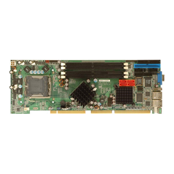
1.2 WSB-9154 Overview 1.2.1 WSB-9154 Overview Photo The WSB-9154 has a wide variety of internal and external peripheral connectors. A labeled photo of the peripheral connectors on the front of the WSB-9154 is shown in Figure 1-1. Figure 1-1: WSB-9154 Overview 1.2.2 WSB-9154 Peripheral Connectors and Jumpers... -
Page 22: Technical Specifications
1 x USB port connectors 1 x VGA connector The WSB-9154 has the following on-board jumpers: Clear CMOS 1.2.3 Technical Specifications WSB-9154 technical specifications are listed in Table 1-1. See Chapter 2 for details. Specification WSB-9154 Form Factor PICMG 1.0 LGA775 Intel®... -
Page 23: Table 1-1: Technical Specifications
WSB-9154 CPU Card Specification WSB-9154 ® CRT: Integrated in the Intel 915GV to support CRT Display DVI: Silicon Image SIL1362CLU (DVI model only) BIOS AMI Flash BIOS Audio 7.1 channel or 5.1 channel audio with optional audio kit Dual PCIe GbE Broadcom BCM5787M chipsets Two RS-232 serial ports USB2.0... - Page 24 WSB-9154 CPU Card THIS PAGE IS INTENTIONALLY LEFT BLANK Page 6...
-
Page 25: Detailed Specifications
WSB-9154 CPU Card Chapter Detailed Specifications Page 7... -
Page 26: Overview
WSB-9154 CPU Card 2.1 Overview This chapter describes the specifications and on-board features of the WSB-9154 in detail. 2.2 Dimensions 2.2.1 Board Dimensions The dimensions of the board are listed below: Length: 338mm Width: 122mm Figure 2-1: WSB-9154 Dimensions (mm) -
Page 27: External Interface Panel Dimensions
WSB-9154 CPU Card 2.2.2 External Interface Panel Dimensions External peripheral interface connector panel dimensions are shown in Figure 2-2. Figure 2-2: External Interface Panel Dimensions (mm) Page 9... -
Page 28: Data Flow
WSB-9154 CPU Card 2.3 Data Flow Figure 2-3 shows the data flow between the two on-board chipsets and other components installed on the motherboard and described in the following sections of this chapter. Figure 2-3: Data Flow Block Diagram Page 10... -
Page 29: Compatible Processors
WSB-9154 CPU Card 2.4 Compatible Processors 2.4.1 Compatible Processor Overview The WSB-9154 supports the following LGA775 processors: Intel® Pentium® 4 Intel® Pentium® D ® All of the above processors communicate with the Intel 915GV northbridge chipset through an 800MHz front side bus (FSB). Features of the supported processors are listed in Table 2-1. -
Page 30: Supported Processors
WSB-9154 CPU Card 2.4.2 Supported Processors Specifications for the compatible processors are listed in Table 2-2 below: Family Processor Stepping Cache Size Speed Speed Tech Intel® 3.80 GHz 800 MHz 90 nm 2 MB Pentium® 4 3.80 GHz 800 MHz 90 nm 1 MB 3.80 GHz... -
Page 31: Intel ® 915Gv Memory Support
® 2.5.2 Intel 915GV Memory Support WARNING! Only DDR2 memory modules can be installed on the WSB-9154. Do not install DDR memory modules. If a DDR memory module is installed on the WSB-9154, the WSB-9154 may be irreparably damaged. ®... -
Page 32: Intel ® 915Gv Integrated Graphics
WSB-9154 CPU Card ® 2.5.3 Intel 915GV Integrated Graphics ® The Intel® 915GV northbridge chipset has an Intel Third-generation Graphics Core graphics engine that supports the following display devices: Analog CRT S-DVO ports ® 2.5.3.1 Intel 915GV Analog CRT Support A DB-15 VGA connector on the external peripheral interface connector panel is interfaced ®... -
Page 33: Intel ® Ich6 Southbridge Chipset
Real-time clock Timer functions Integrated Serial ATA host controller with DMA operations interfaced to four SATA connectors on the WSB-9154 Integrated IDE controller supports Ultra ATA 100/66/33 Supports USB 2.0 devices with four UHCI controllers and one EHCI controller Complies with System Management Bus (SMBus) Specification, Version 2.0 Supports Audio Codec ’97 (AC’97) Revision 2.3... -
Page 34: Intel ® High Definition Audio Controller
WSB-9154 CPU Card to six PCM audio output channels. Complete surround sound requires six-channel audio consisting of: Front left Front right Back left Back right Center Subwoofer ® 2.6.3 Intel High Definition Audio Controller ® The Intel High Definition Audio controller integrated into the ICH6 is connected to the on-board audio connector. -
Page 35: Intel ® Ich6 Ide Interface
WSB-9154 CPU Card ® 2.6.4 Intel ICH6 IDE Interface The integrated IDE interface on the ICH6 southbridge supports two IDE hard disks and ATAPI devices. PIO IDE transfers up to 16MB/s and Ultra ATA transfers of 100MB/s. The integrated IDE interface is able to support the following IDE HDDs:... -
Page 36: Intel ® Ich6 Isa Interface
WSB-9154 CPU Card 5V tolerant PCI signals (except PME#) Integrated PCI arbiter supports up to seven external PCI bus masters The PCI bus is connected to an interface gold finger on the bottom of the CPU card and supports four expansion PCI cards on the backplane. See Figure 2-5. -
Page 37: Intel ® Ich6 Real Time Clock
Up to eight high-speed, full-speed or low-speed USB devices are supported by the ICH6 on the WSB-9154. High-speed USB 2.0, with data transfers of up to 480MB/s, is enabled with the ICH6 integrated Enhanced Host Controller Interface (EHCI) compliant host controller. -
Page 38: Wsb-9154 Usb Implementation
WSB-9154 CPU Card 2.6.10.2 WSB-9154 USB Implementation Only seven of the Intel® ICH6 USB ports are implemented on the WSB-9154. One port is connected to an external connector and six ports are connected to 8-pin on-board headers. See Figure 2-7. -
Page 39: Lpc Bus Components
WSB-9154 CPU Card The Broadcom BCM5787M is a 10/100/1000BASE-T Ethernet LAN controller. The BCM5787M combines a triple-speed IEEE 802.3 compliant Media Access Controller (MAC) with a triple-speed Ethernet transceiver, a PCIe bus interface, and an on-chip buffer memory. Some of the BCM5787 controller features are listed below:... -
Page 40: Super I/O Chipset
WSB-9154 CPU Card Figure 2-9: BIOS Chipset 2.7.3 Super I/O chipset The iTE IT8712F Super I/O chipset is connected to the ICH6 southbridge through the LPC bus. The iTE IT8712F is an LPC interface-based Super I/O device that comes with Environment Controller integration. -
Page 41: Super I/O Lpc Interface
WSB-9154 CPU Card One IEEE 1284 Parallel Port Floppy Disk Controller Keyboard Controller Watchdog Timer Serial IRQ Support Vbat & Vcch Support Single +5V Power Supply Some of the Super I/O features are described in more detail below: 2.7.3.1 Super I/O LPC Interface The LPC interface on the Super I/O complies with the Intel®... -
Page 42: Super I/O Parallel Port
Supports multiple keyboard power on events Supports mouse double-click and/or mouse move power on events 2.8 Environmental and Power Specifications 2.8.1 System Monitoring Three thermal inputs on the WSB-9154 Super I/O monitor the following temperatures: System temperature Power temperature CPU temperature... -
Page 43: Operating Temperature And Temperature Control
2.8.3 Power Consumption Table 2-4 shows the power consumption parameters for the WSB-9154 running with a 3.4GHz Intel® Pentium® 4 processor through an 80MHz FSB and with 2GB of 533MHz DDR2 memory. -
Page 44: Expansion Options
2.9.2 IEI Expansion PICMG 1.0 Backplanes The backplanes listed in Table 2-5 are compatible with the WSB-9154 and can be used to develop highly integrated industrial applications. All of the backplanes listed below have 24-pin ATX connector and a 4-pin ATX connector. - Page 45 WSB-9154 CPU Card Expansion Slots Total System Chassis Model System Compatible Slots Type Type Type Chassis PX-10S-RS-R30 AT/ATX Single PAC-125G-R20 wall-mount PCI-10S2-RS-R30 AT/ATX Single RACK-900G 4U Rack RACK-814G-R20 PCI-12S-RS-R30 AT/ATX Single 4U Rack RACK-3000G-R20 RACK-305G-R20 RACK-360G-R20 PCI-13SD-RS-R30 AT/ATX Dual 4U Rack...
-
Page 46: Iei Chassis
Table 2-5: Compatible IEI PICMG 1.0 Backplanes 2.9.3 IEI Chassis IEI chassis available for WSB-9154 system development are listed in Table 2-6. For more information about these chassis please consult the IEI catalog or contact your vendor, reseller or the IEI sales team at sales@iei.com.tw. - Page 47 WSB-9154 CPU Card Model Slot SBC Mounting Backplanes Slots PCI-14S3-RS-R30 RACK-305G Full-size (4U) Rack PX-14S3-RS-R30 PX-14S5-RS-R30 PCI-13SD-RS-R30 RACK-305G-R20 Full-size (4U) Rack PCI-14S2-RS-R31 PCI-14S3-RS-R30 RACK-360G Full-size (4U) Rack PX-14S3-RS-R30 PX-14S5-RS-R30 PCI-13SD-RS-R30 RACK-360G-R20 Full-size (4U) Rack PCI-14S2-RS-R31 RACK-500G-R20 Full-size (5U) Rack PCI-5S2A-RS-R10...
-
Page 48: Table 2-6: Compatible Iei Chassis
WSB-9154 CPU Card Model Slot SBC Mounting Backplanes Slots PX-20S3-RS-R31 PCI-19S-RS-R30 RACK-3200G Full-size (4U) Rack PX-20S2-RS-R31 PX-20S3-RS-R31 RACK-4000B Full-size (4U) Rack PX-18SQ-RS-R30 PCI-5SD5-RS-R30 PCI-5SD6-RS-R30 RACK-220G Full-size (2U) Rack PCI-5SDA-RS-R30 PCI-6SD-RS-R30 PCI-5SD5-RS-R30 PCI-5SD6-RS-R30 RACK-2000G Full-size (2U) Rack PCI-5SDA-RS-R30 PCI-6SD-RS-R30 Table 2-6: Compatible IEI Chassis... -
Page 49: Unpacking
WSB-9154 CPU Card Chapter Unpacking Page 31... -
Page 50: Anti-Static Precautions
Electrostatic discharge (ESD) can cause serious damage to electronic components, including the WSB-9154. Dry climates are especially susceptible to ESD. It is critical that the following anti-static precautions are strictly adhered to whenever handling the WSB-9154 or any other electrical component. -
Page 51: Unpacking
When the WSB-9154 is unpacked, please do the following: Follow the anti-static precautions outlined in Section 3.1. Make sure the packing box is facing upwards so the WSB-9154 does not fall out of the box. Make sure all the components shown in Section 3.3 are present. -
Page 52: Table 3-1: Package List Contents
WSB-9154 CPU Card Quantity Item and Part Number Image Double RS-232 cable (P/N: 19800-000051-RS) SATA cables (P/N: 32000-062800-RS) SATA power cable (P/N: 32100-088600-RS) DVI IO kit (DVI model only) (P/N: IO-KIT-001-R20) USB cable (P/N: CB-USB02-RS) Mini jumper Pack (P/N: 33100-000079-RS) -
Page 53: Optional Components
WSB-9154 CPU Card 3.3.2 Optional Components The following components are optional: Item and Part Number Image 5.1 Channel Audio Kit (P/N: AC-KIT08R-R10) 7.1 Channel Audio Kit (P/N: AC-KIT-883 HD) ATX 12V Power Cable (P/N: 32100-087100-RS) CPU cooling kit (P/N: CF-520-RS) - Page 54 WSB-9154 CPU Card THIS PAGE IS INTENTIONALLY LEFT BLANK Page 36...
-
Page 55: Connector Pinouts
WSB-9154 CPU Card Chapter Connector Pinouts Page 37... -
Page 56: Peripheral Interface Connectors
WSB-9154 CPU Card 4.1 Peripheral Interface Connectors Section 4.1.1 shows peripheral interface connector locations. Section 4.1.2 lists all the peripheral interface connectors seen in Section 4.1.1. 4.1.1 WSB-9154 Layout Figure 4-1 shows the on-board peripheral connectors, rear panel peripheral connectors and on-board jumpers. -
Page 57: Peripheral Interface Connectors
WSB-9154 CPU Card 4.1.2 Peripheral Interface Connectors Table 4-1 shows a list of the peripheral interface connectors on the WSB-9154. Detailed descriptions of these connectors can be found below. Connector Type Label +12V ATX power supply connector 4-pin ATX connector... -
Page 58: External Peripheral Interface Panel Connectors
WSB-9154 CPU Card 4.1.3 External Peripheral Interface Panel Connectors Table 4-2 lists the external peripheral interface panel connectors on the WSB-9154. Detailed descriptions of these connectors can be found in Section 4.3. Connector Type Label Ethernet connector RJ-45 LAN1 Ethernet connector... -
Page 59: Atx Power Supply Connector (4-Pins)
WSB-9154 CPU Card 4.2.1 ATX Power Supply Connector (4-pins) CN Label: CPU12V1 CN Type: 4-pin ATX power connector (1x4) CN Location: See Figure 4-2 CN Pinouts: See Table 4-3 The 4-pin ATX power supply connector is connected to a +12V ATX power supply. -
Page 60: Atx Power Supply Enable Connector
The ATX power supply enable connector enables the WSB-9154 to be connected to an ATX power supply. In default mode, the WSB-9154 can only us an AT power supply. To enable an ATX power supply the AT Power Select jumper must also be configured. Please refer to Chapter 3 for more details. -
Page 61: Audio Connector (9-Pin)
WSB-9154 CPU Card 4.2.3 Audio Connector (9-pin) CN Label: J_AUDIO1 CN Type: 9-pin header CN Location: See Figure 4-4 CN Pinouts: See Table 4-5 An optional module can be connected to the 10-pin audio connector to provide the system with a high quality AC’97 or Azalia compatible codec that provides a complete integrated audio solution. -
Page 62: Digital Input/Output (Dio) Connector
WSB-9154 CPU Card 4.2.4 Digital Input/Output (DIO) Connector CN Label: DIO1 CN Type: 10-pin header (2x5) CN Location: See Figure 4-5 CN Pinouts: See Table 4-6 The digital input/output connector is managed through a Super I/O chip. The DIO connector pins are user programmable. -
Page 63: Digital Video Interface (Dvi) Connector (Dvi Model Only)
WSB-9154 CPU Card 4.2.5 Digital Video Interface (DVI) Connector (DVI Model Only) CN Label: DVI1 CN Type: 26-pin header CN Location: See Figure 4-6 CN Pinouts: See Table 4-7 The digital video interface connector is a digital visual interface for a digital display. The optional IO-KIT-001 accessory can be purchased separately. -
Page 64: Table 4-7: Dvi Connector Pinouts
WSB-9154 CPU Card DESCRIPTION DESCRIPTION Data 2- +5V Power Data 2+ Hot Plug Detect Data0- Data 0+ DDC Clock DDC Data Data 1- Data 1+ Clock+ Clock- Table 4-7: DVI Connector Pinouts Page 46... -
Page 65: Fan Connector (+12V)
WSB-9154 CPU Card 4.2.6 Fan Connector (+12V) CN Label: CPU_FAN1 CN Type: 4-pin header CN Location: See Figure 4-7 CN Pinouts: See Table 4-8 The cooling fan connector provides a 12V, 500mA current to a system cooling fan. The connector has a "rotation" pin to get rotation signals from fans and notify the system so the system BIOS can recognize the fan speed. -
Page 66: Floppy Disk Connector (34-Pin)
WSB-9154 CPU Card 4.2.7 Floppy Disk Connector (34-pin) CN Label: FDD1 CN Type: 34-pin header (2x17) CN Location: See Figure 4-8 CN Pinouts: See Table 4-9 The floppy disk connector is connected to a floppy disk drive. Figure 4-8: FDD Connector Location... -
Page 67: Front Panel Connector (14-Pin)
WSB-9154 CPU Card DESCRIPTION DESCRIPTION DIRECTION# STEP# WRITE DATA# WRITE GATE# TRACK 0# WRITE PROTECT# READ DATA# SIDE 1 SELECT# DISK CHANGE# Table 4-9: FDD Connector Pinouts 4.2.8 Front Panel Connector (14-pin) CN Label: F_PANEL1 CN Type: 14-pin header (2x6) -
Page 68: Ide Connector(40-Pin)
Table 4-10: Front Panel Connector Pinouts 4.2.9 IDE Connector(40-pin) CN Label: IDE1 CN Type: 40-pin header (2x20) CN Location: See Figure 4-10 CN Pinouts: See Table 4-11 One 40-pin IDE device connector on the WSB-9154 supports connectivity to two hard disk drives. Page 50... -
Page 69: Figure 4-10: Ide Device Connector Locations
WSB-9154 CPU Card Figure 4-10: IDE Device Connector Locations Page 51... -
Page 70: Infrared Interface Connector (5-Pin)
WSB-9154 CPU Card DESCRIPTION DESCRIPTION RESET# GROUND DATA 7 DATA 8 DATA 6 DATA 9 DATA 5 DATA 10 DATA 4 DATA 11 DATA 3 DATA 12 DATA 2 DATA 13 DATA 1 DATA 14 DATA 0 DATA 15 GROUND... -
Page 71: Keyboard Connector
WSB-9154 CPU Card Figure 4-11: Infrared Connector Pinout Locations DESCRIPTION IR-RX IR-TX Table 4-12: Infrared Connector Pinouts 4.2.11 Keyboard Connector CN Label: CN Type: 5-pin wafer (1x5) CN Location: See Figure 4-12 CN Pinouts: See Table 4-13 The keyboard connector can be connected to a standard PS/2 cable to add keyboard functionality to the system. -
Page 72: Parallel Port Connector
WSB-9154 CPU Card Figure 4-12: Keyboard Connector Location DESCRIPTION KEYBOARD CLOCK KEYBOARD DATA GROUND Table 4-13: Keyboard Connector Pinouts 4.2.12 Parallel Port Connector CN Label: LPT1 CN Type: 26-pin box header CN Location: See Figure 4-13 CN Pinouts: See Table 4-14 The 26-pin parallel port connector connects to a parallel port connector interface or some other parallel port device such as a printer. -
Page 73: Figure 4-13: Parallel Port Connector Location
WSB-9154 CPU Card Figure 4-13: Parallel Port Connector Location DESCRIPTION DESCRIPTION STROBE# DATA 0 DATA 1 DATA 2 DATA 3 DATA 4 DATA 5 DATA 6 DATA 7 ACKNOWLEDGE BUSY PAPER EMPTY PRINTER SELECT AUTO FORM FEED # ERROR# INITIALIZE... -
Page 74: Sata Drive Connectors
WSB-9154 CPU Card 4.2.13 SATA Drive Connectors CN Label: SATA1, SATA2, SATA3 and SATA4 CN Type: 7-pin SATA drive connectors CN Location: See Figure 4-14 CN Pinouts: See Table 4-15 The four SATA drive connectors are each connected to a second generation SATA drive. -
Page 75: Serial Port Connectors
WSB-9154 CPU Card 4.2.14 Serial Port Connectors CN Label: COM1 and COM2 CN Type: 10-pin box header (2x5) CN Location: See Figure 4-15 CN Pinouts: See Table 4-16 The 10-pin serial port connector provides a second RS-232 serial communications channel. The serial port connectors can be connected to external RS-232 serial port devices. -
Page 76: Usb Connectors (Internal)
WSB-9154 CPU Card 4.2.15 USB Connectors (Internal) CN Label: USB01, USB23 and USB45 CN Type: 8-pin header (2x4) CN Location: See Figure 4-16 CN Pinouts: See Table 4-17 The 2x4 USB pin connectors each provide connectivity to two USB 1.1 or two USB 2.0 ports. -
Page 77: External Peripheral Interface Connector Panel
WSB-9154 CPU Card 4.3 External Peripheral Interface Connector Panel Figure 4-17 shows the WSB-9154 rear panel. The WSB-9154 rear panel consists of two RJ-45 Ethernet connectors, a PS/2 keyboard connector a USB port and a VGA connector. These connectors are accessible when the WSB-9154 is installed in a chassis. -
Page 78: Keyboard/Mouse Connector
CN Type: PS/2 CN Location: See Figure 4-17 CN Pinouts: See Figure 4-18 and Table 4-18 The WSB-9154 keyboard and mouse connector is a standard PS/2 connector. Figure 4-18: PS/2 Pinout and Configuration DESCRIPTION KB DATA MS DATA KB CLOCK... -
Page 79: Lan Connectors
CN Pinouts: See Table 4-19 The WSB-9154 has two built-in GbE Ethernet controllers. The controllers can connect to the LAN through two RJ-45 LAN connectors. There are two LEDs on the connector indicating the status of LAN. The pin assignments are listed in the following table:... -
Page 80: Usb Connector
CN Location: See Figure 4-17 and Figure 4-20 CN Pinouts: See Table 4-21 The WSB-9154 has a one external USB 2.0 port. The port connects to both USB 2.0 and USB 1.1 devices. Figure 4-20: USB Connector Pinout Locations DESCRIPTION... -
Page 81: Vga Connector
VGA1 CN Type: 15-pin Female CN Location: See Figure 4-17 CN Pinouts: See Figure 4-21 and Table 4-22 The WSB-9154 has a single 15-pin female connector for connectivity to standard display devices. Figure 4-21: VGA Connector DESCRIPTION DESCRIPTION GREEN BLUE... - Page 82 WSB-9154 CPU Card THIS PAGE IS INTENTIONALLY LEFT BLANK Page 64...
-
Page 83: Installation
WSB-9154 CPU Card Chapter Installation Page 65... -
Page 84: Anti-Static Precautions
Electrostatic discharge (ESD) can cause serious damage to electronic components, including the WSB-9154. Dry climates are especially susceptible to ESD. It is therefore critical that whenever the WSB-9154, or any other electrical component is handled, the following anti-static precautions are strictly adhered to. -
Page 85: Installation Considerations
WSB-9154 is installed. All installation notices pertaining to the installation of the WSB-9154 should be strictly adhered to. Failing to adhere to these precautions may lead to severe damage of the WSB-9154 and injury to the person installing the motherboard. 5.2.1 Installation Notices... -
Page 86: Installation Checklist
WSB-9154 CPU Card When working with the WSB-9154, make sure that it is disconnected from all power supplies and that no electricity is being fed into the system. Before and during the installation of the WSB-9154 DO NOT: Remove any of the stickers on the PCB board. These stickers are required for warranty validation. -
Page 87: Cpu, Cpu Cooling Kit And Dimm Installation
Running a CPU without a cooling kit may also result in injury to the user. The CPU, CPU cooling kit and DIMM are the most critical components of the WSB-9154. If one of these component is not installed the WSB-9154 cannot run. -
Page 88: Figure 5-1: Intel Lga775 Socket
The LGA775 socket is shown in Figure 5-1. Figure 5-1: Intel LGA775 Socket To install an LGA775 CPU onto the WSB-9154, follow the steps below: WARNING! When handling the CPU, only hold it on the sides. DO NOT touch the pins at the bottom of the CPU. -
Page 89: Figure 5-2: Remove The Cpu Socket Protective Shield
WSB-9154 CPU Card Figure 5-2: Remove the CPU Socket Protective Shield Step 2: Open the socket. Disengage the load lever by pressing the lever down and slightly outward to clear the retention tab. Rotate the load lever to a fully open position. -
Page 90: Figure 5-4: Insert The Socket Lga775 Cpu
WSB-9154 CPU Card Step 4: Orientate the CPU properly. Make sure the IHS (Integrated Heat Sink) side is facing upward. Step 5: Correctly position the CPU. Match the Pin 1 mark with the cut edge on the CPU socket. Step 6: Align the CPU pins. -
Page 91: Lga775 Cooling Kit Installation
WARNING! It is strongly recommended that you DO NOT use the original heat sink and cooler provided by Intel on the WSB-9154. IEI’s LGA775 cooling kits (CF-775A-RS and CF-520) include a support bracket that is combined with the heat sink mounted on the CPU to counterweigh and balance the load on both sides of the PCB. -
Page 92: Figure 5-6: Securing The Heat Sink To The Pcb Board
Step 6: Connect the fan cable. Connect the cooling kit fan cable to the fan connector on the WSB-9154. Carefully route the cable and avoid heat generating chips and fan blades. Step 0:... -
Page 93: Dimm Installation
5.3.3 DIMM Installation WARNING! Using incorrectly specified DIMM may cause permanent damage the WSB-9154. Please make sure the purchased DIMM complies with the memory specifications of the WSB-9154. DIMM specifications compliant with the WSB-9154 are listed in Chapter 2. To install a DIMM into a DIMM socket, please follow the steps below and refer to Figure 5-7. -
Page 94: Jumper Settings
OPEN a jumper means removing the Figure 5-8: Jumpers plastic clip from a jumper. Before the WSB-9154 is installed in the system, the jumpers must be set in accordance with the desired configuration. The jumpers on the WSB-9154 are listed in Table 5-1. Description... -
Page 95: Clear Cmos Jumper
Jumper Location: See Figure 5-9 If the WSB-9154 fails to boot due to improper BIOS settings, the clear CMOS jumper clears the CMOS data and resets the system BIOS information. To do this, use the jumper cap to close pins 2 and 3 for a few seconds then reinstall the jumper clip back to pins 1 and 2. -
Page 96: Chassis Installation
The WSB-9154 must be installed in a chassis with ventilation holes on the sides allowing airflow to travel through the heat sink surface. In a system with an individual power supply unit, the cooling fan of a power supply can also help generate airflow through the board surface. -
Page 97: Backplane Installation
5.5.2 Backplane Installation Before the WSB-9154 can be installed into the chassis, a backplane must first be installed. Please refer to the installation instructions that came with the backplane and the chassis to see how to install the backplane into the chassis. -
Page 98: Internal Peripheral Device Connections
The following sections describe the cable connections to the CPU card. 5.6.2 IDE Cable Connection The IDE flat cable connects to the WSB-9154 to one or two IDE devices. To connect an IDE HDD to the WSB-9154 please follow the instructions below. -
Page 99: Figure 5-10: Ide Cable Connection
WSB-9154 CPU Card Step 2: Insert the connector. Connect the IDE cable connector to the on-board connector. See Figure 5-10. A key on the front of the cable connector ensures it can only be inserted in one direction. Figure 5-10: IDE Cable Connection Step 3: Connect the cable to an IDE device. -
Page 100: Fdd Cable Connection
Send any queries to sales@iei.com.tw. The FDD flat cable connects to the WSB-9154 to one FDD device. To connect an FDD to the WSB-9154 please follow the instructions below. Step 1: Locate the FDD connector. -
Page 101: Channel Audio Kit Installation
5.6.4 5.1 Channel Audio Kit Installation NOTE: This is an optional item that must be ordered separately. For further information please contact the nearest WSB-9154 distributor, reseller or vendor or contact an iEi sales representative directly. Send any queries to sales@iei.com.tw. -
Page 102: Figure 5-12: 5.1 Channel Audio Kit
The optional 5.1 channel audio kit connects to the 10-pin audio connector on the WSB-9154. The audio kit consists of three audio jacks. One audio jack, Mic In, connects to a microphone. The remaining two audio jacks, Line-In and Line-Out, connect to two speakers. -
Page 103: Channel Audio Kit Installation
The optional 7.1 channel audio kit connects to the 10-pin audio connector on the WSB-9154. The audio kit consists of five audio jacks. One audio jack, Mic In, connects to a microphone. The remaining four audio jacks, Line-In, Front-Out, Rear-Out, and Center Subwoofer, connect to speakers. -
Page 104: Dual Rs-422/485 Cables
0: 5.6.6 Dual RS-422/485 Cables The WSB-9154 is shipped with one RS-422/485 dual serial port connector cable. The dual serial port connector cable connects the serial port connectors on the cable to the RS-422/485 serial port connectors on the WSB-9154. Follow the steps below to connect the dual serial port connector cable. -
Page 105: Usb Cable (Dual Port)
DB-9 connectors should be secured to the chassis with retention screws.Step 0: 5.6.7 USB Cable (Dual Port) The WSB-9154 is shipped with a dual port USB 2.0 cable. To connect the USB cable connector, please follow the steps below. Step 1: Locate the connectors. -
Page 106: Figure 5-15: Dual Usb Cable Connection
Step 3: Insert the cable connectors. Once the cable connectors are properly aligned with the USB connectors on the WSB-9154, connect the cable connectors to the on-board connectors. See Figure 5-15. Figure 5-15: Dual USB Cable Connection Step 4: Attach the bracket to the chassis. The USB 2.0 connectors are attached to a bracket. -
Page 107: Parallel Port Cable With Slot Bracket
WSB-9154 LPT box-header connector. See Figure 5-16. Step 3: Insert the cable connectors. Once the cable connector is properly aligned with the 26-pin box-header connector on the WSB-9154, connect the cable connector to the on-board connector. See Figure 5-16. Page 89... -
Page 108: Figure 5-16: Lpt Cable Connection
WSB-9154 CPU Card Figure 5-16: LPT Cable Connection Step 4: Attach the LPT connector bracket to the chassis. The LPT cable connector is connected to a standard external LPT interface connector. To secure the LPT interface connector to the chassis please refer to the installation instructions that came with the chassis. -
Page 109: Sata Drive Connection
Figure 5-17: Connect the LPT Device 5.6.9 SATA Drive Connection The WSB-9154 is shipped with two SATA drive cables and one SATA drive power cable. To connect the SATA drives to the connectors, please follow the steps below. Step 1: Locate the connectors. -
Page 110: Figure 5-18: Sata Drive Cable Connection
WSB-9154 CPU Card Figure 5-18: SATA Drive Cable Connection Step 3: Connect the cable to the SATA disk. Connect the connector on the other end of the cable to the connector at the back of the SATA drive. See Figure 5-19. -
Page 111: External Peripheral Interface Connection
PS/2 Keyboard/Mouse RJ-45 Ethernet cable connectors USB devices VGA monitor To install these devices, connect the corresponding cable connector from the actual device to the corresponding WSB-9154 external peripheral interface connector making sure the pins are properly aligned. Page 93... -
Page 112: Ps/2 Keyboard/Mouse Connection
WSB-9154 CPU Card 5.7.1 PS/2 Keyboard/Mouse Connection The WSB-9154 has a single PS/2 connector on the external peripheral interface panel. The PS/2 connector is connected to a keyboard or mouse. Follow the instructions below to connect a keyboard or mouse to the WSB-9154. -
Page 113: Lan Connection
Chapter 4. Step 2: Align the connectors. Align the RJ-45 connector on the LAN cable with one of the RJ-45 connectors on the WSB-9154. See Figure 5-21. Figure 5-21: LAN Connection Step 3: Insert the LAN cable RJ-45 connector. Once aligned, gently insert the LAN cable RJ-45 connector into the on-board RJ-45 connector. -
Page 114: Usb Device Connection (Single Connector)
5.7.3 USB Device Connection (Single Connector) There are two external USB 2.0 connectors. Both connectors are perpendicular to the WSB-9154. To connect a USB 2.0 or USB 1.1 device, please follow the instructions below. Step 1: Located the USB connectors. The locations of the USB connectors are shown in Chapter 4. -
Page 115: Vga Monitor Connection
WSB-9154 CPU Card 5.7.4 VGA Monitor Connection The WSB-9154 has a single female DB-15 connector on the external peripheral interface panel. The DB-15 connector is connected to a CRT or VGA monitor. To connect a monitor to the WSB-9154, please follow the instructions below. - Page 116 WSB-9154 CPU Card THIS PAGE IS INTENTIONALLY LEFT BLANK Page 98...
-
Page 117: Ami Bios
WSB-9154 CPU Card Chapter AMI BIOS Page 99... -
Page 118: Introduction
WSB-9154 CPU Card 6.1 Introduction A licensed copy of AMI BIOS is preprogrammed into the ROM BIOS. The BIOS setup program allows users to modify the basic system configuration. This chapter describes how to access the BIOS setup program and the configuration options that may be changed. -
Page 119: Getting Help
WSB-9154 CPU Card Function Page Up key Increase the numeric value or make changes Page Dn key Decrease the numeric value or make changes F1 key General help, only for Status Page Setup Menu and Option Page Setup Menu F2 /F3 key Change color from total 16 colors. -
Page 120: Main
WSB-9154 CPU Card The following sections completely describe the configuration options found in the menu items at the top of the BIOS screen and listed above. 6.2 Main The Main BIOS menu (BIOS Menu 1) appears when the BIOS Setup program is entered. -
Page 121: Advanced
WSB-9154 CPU Card The System Overview field also has two user configurable fields: System Time [xx:xx:xx] Use the System Time option to set the system time. Manually enter the hours, minutes and seconds. System Date [xx/xx/xx] Use the System Date option to set the system date. Manually enter the day, month and year. -
Page 122: Cpu Configuration
WSB-9154 CPU Card BIOS Menu 2: Advanced 6.3.1 CPU Configuration Use the CPU Configuration menu (BIOS Menu 3) to view detailed CPU specifications and configure the CPU. BIOS Menu 3: CPU Configuration The CPU Configuration menu lists the following CPU details: Module Version: xx.xx... -
Page 123: Ide Configuration
WSB-9154 CPU Card FSB Speed: Lists the FSB speed Cache L1: Lists the CPU L1 cache size Cache L2: Lists the CPU L2 cache size The following CPU Configuration menu items can be configured. Hyper Threading Function Hyper Threading Function [Enabled] Use the Hyper Threading Function to enable or disable the CPU hyper threading function. -
Page 124: Ata/Ide Configurations [Compatible]
WSB-9154 CPU Card ATA/IDE Configurations [Compatible] Use the ATA/IDE Configurations option to configure the ATA/IDE controller. Disables the on-board ATA/IDE controller. Disabled Configures the on-board ATA/IDE controller to be in Compatible compatible mode. In this mode, a SATA channel will replace one of the IDE channels. -
Page 125: Ide (Master) And Ide (Slave)
WSB-9154 CPU Card IDE (Master) and IDE (Slave) When entering setup, BIOS auto detects the presence of IDE devices. BIOS displays the status of the auto detected IDE devices. The following IDE devices are detected and are shown in the IDE Configuration menu:... -
Page 126: Ide Detect Time Out (Sec) [35]
WSB-9154 CPU Card IDE Detect Time Out (Sec) [35] The IDE Detect Time Out (Sec) BIOS option specifies the maximum time (in seconds) the AMI BIOS will search for IDE devices. This allows fine-tunes the settings to allow for faster boot times. -
Page 127: Ide Master, Ide Slave
WSB-9154 CPU Card Host The motherboard onboard IDE controller detects the type of IDE cable used. The IDE disk drive detects the type of IDE cable Device used. 6.3.2.1 IDE Master, IDE Slave Use the IDE Master and IDE Slave configuration menu (BIOS Menu 5) to view both primary and secondary IDE device details and configure the IDE devices connected to the system. -
Page 128: Type [Auto]
WSB-9154 CPU Card increasing the amount of data transferred. Only 512 bytes of data can be transferred per interrupt if block mode is not used. Block mode allows transfers of up to 64 KB per interrupt. PIO Mode: Indicates the PIO mode of the installed device. -
Page 129: Lba/Large Mode [Auto]
WSB-9154 CPU Card LBA/Large Mode [Auto] Use the LBA/Large Mode option to disable or enable BIOS to auto detects LBA (Logical Block Addressing). LBA is a method of addressing data on a disk drive. In LBA mode, the maximum drive capacity is 137 GB. -
Page 130: Dma Mode [Auto]
WSB-9154 CPU Card PIO mode 0 selected with a maximum transfer rate of 3.3MBps PIO mode 1 selected with a maximum transfer rate of 5.2MBps PIO mode 2 selected with a maximum transfer rate of 8.3MBps PIO mode 3 selected with a maximum transfer rate of 11.1MBps PIO mode 4 selected with a maximum transfer rate of 16.6MBps... -
Page 131: Auto]
WSB-9154 CPU Card UDMA1 Ultra DMA mode 0 selected with a maximum data transfer rate of 16.6MBps Ultra DMA mode 1 selected with a maximum data transfer UDMA1 rate of 25MBps UDMA2 Ultra DMA mode 2 selected with a maximum data transfer rate of 33.3MBps... -
Page 132: Floppy Configuration
WSB-9154 CPU Card Disabled Prevents the BIOS from using 32-bit data transfers. Enabled Allows BIOS to use 32-bit data transfers on supported EFAULT hard disk drives. 6.3.3 Floppy Configuration Use the Floppy Configuration menu (BIOS Menu 6) to configure the floppy disk drive connected to the system. -
Page 133: Super Io Configuration
WSB-9154 CPU Card 6.3.4 Super IO Configuration Use the IO Configuration menu (BIOS Menu 7) to set or change the configurations for the FDD controllers, parallel ports and serial ports. BIOS Menu 7: Super IO Configuration On-board Floppy Controller [Enabled] Use the On-board Floppy Controller to enable or disable the floppy controller. -
Page 134: Serial Port1 Address [3F8/Irq4]
WSB-9154 CPU Card Enabled Can designate A or B to a floppy drive without changing the physical connection Serial Port1 Address [3F8/IRQ4] Use the Serial Port1 Address option to select the Serial Port 1 base address. Disabled No base address is assigned to Serial Port 1... -
Page 135: Serial Port2 Mode [Normal]
WSB-9154 CPU Card 3E8/IRQ4 Serial Port 2 I/O port address is 3E8 and the interrupt address is IRQ4 Serial Port 2 I/O port address is 2E8 and the interrupt 2E8/IRQ3 address is IRQ3 Serial Port2 Mode [Normal] Use the Serial Port2 Mode option to select the Serial Port2 operational mode. -
Page 136: Parallel Port Mode [Normal]
WSB-9154 CPU Card Parallel Port Mode [Normal] Use the Parallel Port Mode option to select the mode the parallel port operates in. The normal parallel port mode is the standard mode Normal EFAULT for parallel port operation. Bi-directional Parallel port outputs are 8-bits long. Inputs are accomplished by reading 4 of the 8 bits on the status register. -
Page 137: Hardware Health Configuration
WSB-9154 CPU Card Parallel Port IRQ [IRQ7] Use the Parallel Port IRQ selection to set the parallel port interrupt address. IRQ5 is assigned as the parallel port interrupt address IRQ5 IRQ7 is assigned as the parallel port interrupt address IRQ7 EFAULT 6.3.5 Hardware Health Configuration... -
Page 138: Fan 2 Mode Setting [Full On Mode]
WSB-9154 CPU Card FAN 2 Mode Setting [Full On Mode] Use the FAN 2 Mode Setting option to configure the second fan. Fan is on all the time Full On Mode EFAULT Fan is off when the temperature is low Automatic mode enough. -
Page 139: Acpi Configuration
WSB-9154 CPU Card 6.3.6 ACPI Configuration The ACPI Configuration menu (BIOS Menu 9) configures the General Configuration and Power Interface (ACPI) option. BIOS Menu 9: ACPI Configuration 6.3.6.1 General ACPI Configuration Use the General ACPI Configuration menu (BIOS Menu 10) to select the ACPI state when the system is suspended. -
Page 140: Mps Configuration
WSB-9154 CPU Card Suspend Mode [S1 (POS)] Use the Suspend Mode option to specify the sleep state the system enters when it is not being used. S1 (POS) The system enters S1 (POS) sleep state. The system EFAULT appears off. The CPU is stopped; RAM is refreshed; the system is running in a low power mode. -
Page 141: Remote Access Configuration
WSB-9154 CPU Card 6.3.8 Remote Access Configuration Use the Remote Access Configuration menu (BIOS Menu 12) to configure remote access parameters. The Remote Access Configuration is an AMIBIOS feature and allows a remote host running a terminal program to display and configure the BIOS settings. -
Page 142: Remote Access [Disabled]
WSB-9154 CPU Card Remote Access [Disabled] Use the Remote Access option to enable or disable access to the remote functionalities of the system. Disabled Remote access is disabled. EFAULT Enabled Remote access configuration options shown below appear: Serial Port Number... -
Page 143: Usb Configuration
WSB-9154 CPU Card 6.3.9 USB Configuration Use the USB Configuration menu (BIOS Menu 13) to read USB configuration information and configure the USB settings. BIOS Menu 13: USB Configuration USB Configuration The USB Configuration field shows the system USB configuration. The items listed are: Module Version: x.xx.x-xx.x... -
Page 144: Legacy Usb Support [Disabled]
WSB-9154 CPU Card 4 USB Ports Four USB ports are enabled 6 USB Ports Six USB ports are enabled 8 USB Ports Eight USB ports are enabled EFAULT Legacy USB Support [Disabled] Use the Legacy USB Support BIOS option to enable USB mouse and USB keyboard support. -
Page 145: Pci/Pnp
WSB-9154 CPU Card 6.4 PCI/PnP Use the PCI/PnP menu (BIOS Menu 14) to configure advanced PCI and PnP settings. WARNING! Setting wrong values for the BIOS selections in the PCI/PnP BIOS menu may cause the system to malfunction. BIOS Menu 14: PCI/PnP Configuration... -
Page 146: Plug & Play O/S [No]
WSB-9154 CPU Card Plug & Play O/S [No] Use the Plug & Play O/S BIOS option to specify whether system plug and play devices are configured by the operating system or the BIOS. If the operating system does not meet the Plug and Play... -
Page 147: Allocate Irq To Pci Vga [Yes]
WSB-9154 CPU Card Allocate IRQ to PCI VGA [Yes] Use the Allocate IRQ to PCI VGA option to restrict the system from giving the VGA adapter card an interrupt address. Assigns an IRQ to a PCI VGA card if card requests IRQ... -
Page 148: Dma Channel# [Available]
WSB-9154 CPU Card DMA Channel# [Available] Use the DMA Channel# option to assign a specific DMA channel to a particular PCI/PnP device. Available The specified DMA is available to be used by EFAULT PCI/PnP devices Reserved The specified DMA is reserved for use by Legacy... -
Page 149: Boot
WSB-9154 CPU Card 6.5 Boot Use the Boot menu (BIOS Menu 15) to configure system boot options. BIOS Menu 15: Boot Page 131... -
Page 150: Boot Settings Configuration
WSB-9154 CPU Card 6.5.1 Boot Settings Configuration Use the Boot Settings Configuration menu (BIOS Menu 16) to configure advanced system boot options. BIOS Menu 16: Boot Settings Configuration Quick Boot [Enabled] Use the Quick Boot BIOS option to make the computer speed up the boot process. -
Page 151: Addon Rom Display Mode [Force Bios]
WSB-9154 CPU Card AddOn ROM Display Mode [Force BIOS] Use the AddOn ROM Display Mode option to allow add-on ROM (read-only memory) messages to be displayed. Force BIOS The system forces third party BIOS to display EFAULT during system boot. -
Page 152: Ps/2 Mouse Support [Auto]
WSB-9154 CPU Card Allows the Number Lock on the keyboard to be enabled EFAULT automatically when the computer system boots up. This allows the immediate use of the 10-key numeric keypad located on the right side of the keyboard. To confirm this, the Number Lock LED light on the keyboard is lit. -
Page 153: Boot Device Priority
WSB-9154 CPU Card 6.5.2 Boot Device Priority Use the Boot Device Priority menu (BIOS Menu 17) to specify the boot sequence from the available devices. Possible boot devices may include: FLOPPY DRIVE CD/DVD BIOS Menu 17: Boot Device Priority Settings... -
Page 154: Hard Disk Drives
WSB-9154 CPU Card 6.5.3 Hard Disk Drives Use the Hard Disk Drives menu ( BIOS Menu 18) to specify the boot sequence of the available HDDs. When the menu is opened, the HDDs connected to the system are listed as shown below:... -
Page 155: Removable Drives
WSB-9154 CPU Card 6.5.4 Removable Drives Use the Removable Drives menu (BIOS Menu 19) to specify the boot sequence of the available FDDs. When the menu is opened, the FDDs connected to the system are listed as shown below: 1st Drive... -
Page 156: Security
WSB-9154 CPU Card 6.6 Security Use the Security menu (BIOS Menu 20) to set system and user passwords. BIOS Menu 20: Security Change Supervisor Password Use the Change Supervisor Password to set or change a supervisor password. The default for this option is Not Installed. If a supervisor password must be installed, select this field and enter the password. -
Page 157: Change User Password
WSB-9154 CPU Card Change User Password Use the Change User Password to set or change a user password. The default for this option is Not Installed. If a user password must be installed, select this field and enter the password. After the password has been added, Install appears next to Change User Password. -
Page 158: Chipset
WSB-9154 CPU Card 6.7 Chipset Use the Chipset menu (BIOS Menu 21) to access the NorthBridge and SouthBridge configuration menus. WARNING! Setting the wrong values for the Chipset BIOS selections in the Chipset BIOS menu may cause the system to malfunction. -
Page 159: Northbridge Configuration
WSB-9154 CPU Card 6.7.1 NorthBridge Configuration Use the NorthBridge Configuration menu (BIOS Menu 22) to configure the northbridge chipset. BIOS Menu 22:NorthBridge Chipset Configuration Memory Hole [Disabled] Use the Memory Hole option to reserve memory space between 15MB and 16MB for ISA expansion cards that require a specified area of memory to work properly. -
Page 160: Video Function Configuration
WSB-9154 CPU Card PEG/IGD PEG/PCI PCI/PEG PCI/IGD EFAULT Internal Graphics Mode Select [Enabled, 8MB] Use the Internal Graphic Mode Select option to specify the amount of system memory that can be used by the Internal graphics device. Disabled Enabled, 1MB... -
Page 161: Dvmt Mode Select [Combo Mode]
WSB-9154 CPU Card DVMT Mode Select [Combo Mode] Use the DVMT Mode Select option to select the Intel Dynamic Video Memory Technology (DVMT) operating mode. Fixed Mode A fixed portion of graphics memory is reserved as graphics memory. DVMT Mode... -
Page 162: Southbridge Chipset Configuration
WSB-9154 CPU Card 6.7.2 SouthBridge Chipset Configuration The SouthBridge Chipset Configuration menu (BIOS Menu 23) the southbridge chipset to be configured. BIOS Menu 23:SouthBridge Chipset Configuration Azalia/AC97 Selection [AC’97 Audio Only] Use the Azalia/AC97 Selection option to enable or disable the Azalia or AC’97 CODECs. -
Page 163: Giga Lan Controller [Enabled]
WSB-9154 CPU Card Giga LAN Controller [Enabled] The Giga LAN Controller option enables or disables the on-board LAN. The onboard LAN device automatically detected and enabled Enabled EFAULT Onboard LAN device manually disabled Disabled Spread Spectrum Mode [Disabled] Use the Spread Spectrum Mode option to reduce the EMI. Excess EMI is generated when the system clock generator pulses have extreme values. -
Page 164: Power
WSB-9154 CPU Card 6.8 Power The Power menu (BIOS Menu 24) allows the advanced power management options to be configured. BIOS Menu 24: Power Power Management/APM [Enabled] The Power Management/APM BIOS option accesses the advanced power management features. Disabled Disables the Advanced Power Management (APM) -
Page 165: Power Button Mode [On/Off]
WSB-9154 CPU Card Power Button Mode [On/Off] The Power Button Mode BIOS specifies how the power button functions. On/Off When the power button is pressed the system is either EFAULT turned on or off Standby When the power button is pressed the system goes into... -
Page 166: Exit
WSB-9154 CPU Card Disabled The real time clock (RTC) cannot generate a wake EFAULT event If selected, the following appears with values that Enabled can be selected: RTC Alarm Date (Days) System Time After setting the alarm, the computer turns itself on from a suspend state when the alarm goes off. -
Page 167: Save Changes And Exit
WSB-9154 CPU Card Save Changes and Exit Use the Save Changes and Exit option to save the changes made to the BIOS options and to exit the BIOS configuration setup program. Discard Changes and Exit Use the Discard Changes and Exit option to exit the BIOS configuration setup program without saving the changes made to the system. - Page 168 WSB-9154 CPU Card THIS PAGE IS INTENTIONALLY LEFT BLANK Page 150...
-
Page 169: Driver Installation
WSB-9154 CPU Card Chapter Driver Installation Page 151... -
Page 170: Available Software Drivers
IDE controller (IT8211) Installation instructions are given below. 7.2 Driver CD Auto-run All the drivers for the WSB-9154 are on the CD that came with the system. To install the drivers, please follow the steps below. Step 1: Insert the CD into a CD drive connected to the system. -
Page 171: Figure 7-1: Introduction Screen
WSB-9154 CPU Card Step 2: The driver main menu appears (Figure 7-1). Figure 7-1: Introduction Screen Step 3: Click WSB-9154. Step 4: A new screen with a list of available drivers appears (Figure 7-2). Figure 7-2: Available Drivers Page 153... -
Page 172: Intel ® Chipset Driver Installation
WSB-9154 CPU Card Step 5: Select the driver to install from the list in Figure 7-2. Detailed driver installation instructions follow below. Step 0: ® 7.3 Intel Chipset Driver Installation To install the chipset driver, please follow the steps below. -
Page 173: Figure 7-4: Chipset Driver Installation Welcome Screen
WSB-9154 CPU Card Figure 7-4: Chipset Driver Installation Welcome Screen Step 5: Click N to continue the installation process. Step 6: The license agreement in Figure 7-5 appears. Figure 7-5: Chipset Driver Installation License Agreement Step 7: Read the license agreement. To accept the terms and conditions stipulated in... -
Page 174: Figure 7-6: Chipset Driver Readme File Information
WSB-9154 CPU Card Step 8: The Readme file in Figure 7-6 appears. Figure 7-6: Chipset Driver Readme File Information Step 9: Read the Readme file information and then click N to start the driver installation. Page 156... -
Page 175: Intel ® Graphics Media Accelerator Driver Installation
WSB-9154 CPU Card Step 10: After the driver installation process is complete, a confirmation screen appears (Figure 7-7). Figure 7-7: Chipset Driver Installation Complete Step 11: Click F to complete the driver installation. Step 0: INISH ® 7.4 Intel Graphics Media Accelerator Driver Installation To install the chipset driver, please follow the steps below. -
Page 176: Figure 7-8: Select The Operating System
WSB-9154 CPU Card Figure 7-8: Select the Operating System Step 3: Double-click the appropriate operating system folder. Step 4: A new window appears (Figure 7-9). Figure 7-9: VGA Driver Step 5: Double-click the installation program icon to continue the installation process. -
Page 177: Figure 7-10: Intel® Graphics Media Accelerator Installshield Wizard
WSB-9154 CPU Card Figure 7-10: Intel® Graphics Media Accelerator InstallShield Wizard Step 7: Read the Readme file information and click N to begin extracting files (Figure 7-11). Figure 7-11: InstallShield Wizard Extracting Files Page 159... -
Page 178: Figure 7-12: Intel® Graphics Media Accelerator Driver Welcome Screen
WSB-9154 CPU Card Step 8: The Graphics Media Accelerator Driver Welcome screen appears (Figure 7-12). Figure 7-12: Intel® Graphics Media Accelerator Driver Welcome Screen Step 9: Click N and a license agreement appears (Figure 7-13). Figure 7-13: Intel® Graphics Media Accelerator Driver License Agreement... -
Page 179: Figure 7-14: Intel® Graphics Media Accelerator Driver Installing Notice
WSB-9154 CPU Card Step 10: Read the license agreement. To accept the terms and conditions stipulated in the license agreement shown, click Y and the installation notice appears (Figure 7-14) as the driver is installed. Figure 7-14: Intel® Graphics Media Accelerator Driver Installing Notice... -
Page 180: Broadcom Lan Driver (For Gbe Lan) Installation
WSB-9154 CPU Card 7.5 Broadcom LAN Driver (for GbE LAN) Installation To install the Broadcom LAN driver, please follow the steps below. Step 1: Open Windows Control Panel (Figure 7-16). Figure 7-16: Windows Control Panel Step 2: Double-click the System icon (Figure 7-17). -
Page 181: Figure 7-17: System Icon
WSB-9154 CPU Card Figure 7-17: System Icon Step 3: Click the Device Manager tab (Figure 7-18). Page 163... -
Page 182: Figure 7-18: Device Manager Tab
WSB-9154 CPU Card Figure 7-18: Device Manager Tab Step 4: A list of system hardware devices appears (Figure 7-19). Page 164... -
Page 183: Figure 7-19: Device Manager List
WSB-9154 CPU Card Figure 7-19: Device Manager List Step 5: Double-click the listed device that has question marks next to it (this means Windows does not recognize the device). Step 6: The Device Driver Wizard appears (Figure 7-20). Page 165... -
Page 184: Figure 7-20: Search For Suitable Driver
WSB-9154 CPU Card Figure 7-20: Search for Suitable Driver Step 7: Select “Search for a suitable driver for my device (recommended),” and click to continue. Step 8: Select “Specify a Location” in the Locate Driver Files window (Figure 7-21). Figure 7-21: Locate Driver Files... -
Page 185: Realtek Ac`97 Audio Driver (Alc665) Installation
WSB-9154 CPU Card Step 10: The Locate File window appears (Figure 7-22). Figure 7-22: Location Browsing Window Step 11: Select the proper OS folder under the “X:\3-LAN\BROADCOM BCM57xx Drivers” directory in the Locate File window, where “X:\” is the system CD drive. -
Page 186: Figure 7-23: Select The Audio Codec
WSB-9154 CPU Card Step 1: Select AUDIO from the list in Figure 7-2. Step 2: A new window opens (Figure 7-23). Figure 7-23: Select the Audio CODEC Step 3: Double-click the ALC665 folder. Step 4: Double-click the Setup.exe program icon in Figure 7-24. -
Page 187: Figure 7-24: Locate The Setup Program Icon
WSB-9154 CPU Card Figure 7-24: Locate the Setup Program Icon Step 5: The InstallShield Wizard is prepared to guide the user through the rest of the process (Figure 7-25). Figure 7-25: Preparing Setup Screen Step 6: Once initialized, the InstallShield Wizard welcome screen appears (Figure 7-26). -
Page 188: Figure 7-26: Installshield Wizard Welcome Screen
WSB-9154 CPU Card Figure 7-26: InstallShield Wizard Welcome Screen Step 7: Click N to continue the installation. Step 8: InstallShield starts to install the new software as shown in Figure 7-27. Figure 7-27: Audio Driver Software Configuration Step 9: At this stage the Digital Signal Not Found screen shown in Figure 7-28 appears. -
Page 189: Figure 7-28: Audio Driver Digital Signal
WSB-9154 CPU Card Figure 7-28: Audio Driver Digital Signal Step 10: Click Y and the driver installation begins (Figure 7-29). Figure 7-29: Audio Driver Installation Step 11: After the driver installation process is complete, a confirmation screen appears (Figure 7-30). -
Page 190: Realtek Hd Audio Driver (Alc883) Installation
WSB-9154 CPU Card Figure 7-30: Restart the Computer Step 12: The confirmation screen offers the option of restarting the computer now or later. For the settings to take effect, the computer must be restarted. Click F INISH restart the computer. -
Page 191: Figure 7-31: Select The Audio Codec
WSB-9154 CPU Card Step 2: A new window opens (Figure 7-31). Figure 7-31: Select the Audio CODEC Step 3: Double-click the ALC883 folder. Page 173... -
Page 192: Figure 7-32: Select The Os
WSB-9154 CPU Card Step 4: Double-click the appropriate operating system folder (Figure 7-32). Figure 7-32: Select the OS Page 174... -
Page 193: Figure 7-33: Select The Os Version
WSB-9154 CPU Card Step 5: Double-click the appropriate operating system version folder (Figure 7-33). Figure 7-33: Select the OS Version Step 6: Double-click the Setup.exe program icon in Figure 7-34. Page 175... -
Page 194: Figure 7-34: Locate The Setup Program Icon
WSB-9154 CPU Card Figure 7-34: Locate the Setup Program Icon Step 7: The InstallShield Wizard starts (Figure 7-35). Figure 7-35: The InstallShield Wizard Starts Step 8: The InstallShield Wizard is prepared to guide the user through the rest of the process (Figure 7-36). -
Page 195: Figure 7-36: Preparing Setup Screen
WSB-9154 CPU Card Figure 7-36: Preparing Setup Screen Step 9: Once initialized, the InstallShield Wizard welcome screen appears (Figure 7-37). Figure 7-37: InstallShield Wizard Welcome Screen Step 10: Click N to continue the installation. Step 11: InstallShield starts to install the new software as shown in Figure 7-38. -
Page 196: Figure 7-38: Audio Driver Software Configuration
WSB-9154 CPU Card Figure 7-38: Audio Driver Software Configuration Step 12: The Installation Wizard updates the system as shown in Figure 7-39. Figure 7-39: Installation Wizard Updates the System Step 13: After the driver installation process is complete, a confirmation screen appears (Figure 7-40). -
Page 197: Ide Controller Installation
WSB-9154 CPU Card Figure 7-40: Restart the Computer Step 14: The confirmation screen offers the option of restarting the computer now or later. For the settings to take effect, the computer must be restarted. Click F INISH restart the computer. -
Page 198: Figure 7-41: Access Windows Control Panel
WSB-9154 CPU Card Figure 7-41: Access Windows Control Panel Page 180... -
Page 199: Figure 7-42: Double Click The System Icon
WSB-9154 CPU Card Step 2: Double-click the System icon (Figure 7-42). Figure 7-42: Double Click the System Icon Page 181... -
Page 200: Figure 7-43: Double Click The Device Manager Tab
WSB-9154 CPU Card Step 3: Click the Device Manager tab (Figure 7-43). Figure 7-43: Double Click the Device Manager Tab Page 182... -
Page 201: Figure 7-44: Device Manager List
WSB-9154 CPU Card Step 4: A list of system hardware devices appears (Figure 7-44). Figure 7-44: Device Manager List Step 5: Double-click the listed device that has question marks next to it (This means Windows does not recognize the device). -
Page 202: Figure 7-45: Search For Suitable Driver
WSB-9154 CPU Card Figure 7-45: Search for Suitable Driver Step 7: Select “Search for a suitable driver for my device (recommended),” and click to continue. Step 8: The Locate Driver Files window (Figure 7-46) appears. Figure 7-46: Locate Driver Files Step 9: Select “Specify a Location”... -
Page 203: Figure 7-47: Location Browsing Window
WSB-9154 CPU Card Step 10: Select the proper OS folder under the “X:\7-IDE\IT8211 v1.3.2.8” directory (Figure 7-47) in the location browsing window, where “X:\” is the system CD drive. Figure 7-47: Location Browsing Window Step 11: Select the iteatapi.inf file, click O and the driver is installed.Step 0:... - Page 204 WSB-9154 CPU Card THIS PAGE IS INTENTIONALLY LEFT BLANK Page 186...
-
Page 205: Abios Menu Options
WSB-9154 CPU Card Appendix BIOS Menu Options Page 187... -
Page 206: Bios Configuration Options
WSB-9154 CPU Card A.1 BIOS Configuration Options Below is a list of BIOS configuration options described in Chapter 6. System Overview ....................102 System Time [xx:xx:xx] ..................103 System Date [xx/xx/xx] ..................103 Hyper Threading Function [Enabled]..............105 ATA/IDE Configurations [Compatible].............. 106 Legacy IDE Channels [PATA Pri, SATA Sec]........... - Page 207 WSB-9154 CPU Card Parallel Port Mode [Normal]................118 Parallel Port IRQ [IRQ7]..................119 H/W Health Function [Enabled] ................. 119 FAN 2 Mode Setting [Full On Mode]..............120 Suspend Mode [S1 (POS)] ................. 122 MPS Revision [1.4]....................122 Remote Access [Disabled]................. 124 Serial Port Number .....................
- Page 208 WSB-9154 CPU Card Interrupt 19 Capture [Disabled] ................. 134 Change Supervisor Password................138 User Access Level [Full Access]............... 138 Change User Password..................139 Clear User Password..................139 Password Check [Setup]..................139 Boot Sector Virus Protection [Disabled] ............139 Memory Hole [Disabled]..................141 Boots Graphics Adapter [PCI/IGD]..............
-
Page 209: Bwatchdog Timer
WSB-9154 CPU Card Appendix Watchdog Timer Page 191... - Page 210 WSB-9154 CPU Card NOTE: The following discussion applies to DOS environment. IEI support is contacted or the IEI website visited for specific drivers for more sophisticated operating systems, e.g., Windows and Linux. The Watchdog Timer is provided to ensure that standalone systems can always recover from catastrophic conditions that cause the CPU to crash.
-
Page 211: Example Program
WSB-9154 CPU Card NOTE: When exiting a program it is necessary to disable the Watchdog Timer, otherwise the system resets. Example program: ; INITIAL TIMER PERIOD COUNTER W_LOOP: AX, 6F02H ;setting the time-out value BL, 30 ;time-out value is 48 seconds ;... - Page 212 WSB-9154 CPU Card THIS PAGE IS INTENTIONALLY LEFT BLANK Page 194...
-
Page 213: Caddress Mapping
WSB-9154 CPU Card Appendix Address Mapping Page 195... -
Page 214: Io Address Map
WSB-9154 CPU Card C.1 IO Address Map I/O address Range Description 000-01F DMA Controller 020-021 Interrupt Controller 040-043 System time 060-06F Keyboard Controller 070-07F System CMOS/Real time Clock 080-09F DMA Controller 0A0-0A1 Interrupt Controller 0C0-0DF DMA Controller 0F0-0FF Numeric data processor... -
Page 215: Irq Mapping Table
WSB-9154 CPU Card C.3 IRQ Mapping Table IRQ0 System Timer IRQ8 RTC clock IRQ1 Keyboard IRQ9 ACPI IRQ2 Available IRQ10 IRQ3 COM2 IRQ11 LAN/USB2.0/SATA IRQ4 COM1 IRQ12 PS/2 mouse IRQ5 SMBus Controller IRQ13 IRQ6 IRQ14 Primary IDE IRQ7 Available IRQ15... - Page 216 WSB-9154 CPU Card THIS PAGE IS INTENTIONALLY LEFT BLANK Page 198...
-
Page 217: Ddio Interface
WSB-9154 CPU Card Appendix DIO Interface Page 199... -
Page 218: Dio Interface Introduction
WSB-9154 CPU Card D.1 DIO Interface Introduction The DIO connector on the WSB-9154 is interfaced to GPIO ports on the ITE Super I/O chipset. The DIO has both 4-bit digital inputs and 4-bit digital outputs. The digital inputs and digital outputs are generally control signals that control the on/off circuit of external devices or TTL devices. -
Page 219: Assembly Language Samples
WSB-9154 CPU Card D.3 Assembly Language Samples D.3.1 Enable the DIO Input Function The BIOS interrupt call INT 15H controls the digital I/O. An assembly program to enable digital I/O input functions is listed below. Sets the digital port as input... - Page 220 WSB-9154 CPU Card THIS PAGE IS INTENTIONALLY LEFT BLANK Page 202...
-
Page 221: Index
WSB-9154 CPU Card Index Page 203... - Page 222 WSB-9154 CPU Card +12V ATX power supply connector....41 backplane location and pinouts ......41 installation..........79 Backplanes ..........26 Benefits ............2 BIOS ACPI ............121 ACPI Configuration......121 Address Mapping Advanced menu........103 1st MB Memory Address Map .....196 advanced power management ... 146 DMA Channel Assignments....197...
- Page 223 WSB-9154 CPU Card Video Function Configuration ....142 parallel port..........54 BIOS Chipset ..........21 SATA drives ...........56 BIOS Menu Options.........187 serial ports ..........57 USB (internal) ........58 cooling............78 airflow ............78 cables ............80 cooling fan........... 47, 73 dual port USB ........87 cooling kit installation .........73 dual serial port........86...
- Page 224 WSB-9154 CPU Card panel ...........9 VGA ............63 DIMM ............75 external switches ........49 installation..........75 specifcations..........75 DIO Interface ...........199 fan connector ..........47 Direct Media Interface (DMI) .....14 location and pinouts.......47 Driver Installation ........151 fan speed controller ........23 Drivers FDD device Broadcom GbE LAN......162 connector..........82...
- Page 225 WSB-9154 CPU Card connector..........80 LGA775 CPU IDE flat cable .........80 cooling kit..........73 IDE flat cable ..........80 cooling kit installation......73 IDE interface ..........17 cooling kit WARNING! ......73 infrared interface........52 installation..........69 Amplitude Shift Key Infrared....52 LPC bus .............21 ASKIR............52 LPC interface ........17, 23 Serial Infrared........52...
- Page 226 WSB-9154 CPU Card peripheral connectors ........40 power cable ...........91 peripheral device cables......80 SATA drive connector.........56 PICMG 1.0 ..........26 location and pinouts.......56 power button ..........49 SATA drives..........56 Power Button Mode .........147 SDVO Support ...........14 Power Consumption ........25 serial port connector ........57 power LED ..........49...
- Page 227 WSB-9154 CPU Card USB 2.0 port ..........62 VGA connector...........63 USB connector, internal......58 VGA monitor..........97 location and pinouts ......58 connection ..........97 USB device connection ......96 single connector ........96 warranty validation ........68 Watchdog Timer........191 VGA ............97 Page 209...
Need help?
Do you have a question about the WSB-9154 and is the answer not in the manual?
Questions and answers