Table of Contents
Advertisement
Quick Links
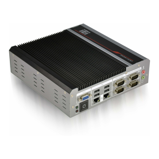
TANK-600 Em b e d de d S ys te m
MODEL:
TANK-600 S e rie s
Fa n le s s Em b e d d e d S ys te m with In te l® Du a l Co re D2550 1.86 GHz
p ro c e s s o r / In te l® Du a l Co re N2600 1.6 GHz p ro c e s s o r, VGA,
Two Gig a b it Eth e rn e t, S ix US B 2.0, RS -232/422/485,
Ro HS Co m p lia n t
Us e r Ma n u a l
P a g e i
Re v. 1.03 – 28 J u ly 2017
Advertisement
Table of Contents

Related Manuals for IEI Technology TANK-600 Series


Summary of Contents for IEI Technology TANK-600 Series
- Page 1 TANK-600 Em b e d de d S ys te m MODEL: TANK-600 S e rie s Fa n le s s Em b e d d e d S ys te m with In te l® Du a l Co re D2550 1.86 GHz p ro c e s s o r / In te l®...
- Page 2 TANK-600 Em b e d d e d S ys te m Re vis io n Date Version Changes 28 July 2017 1.03 Add Manual Conventions Add Section 3.1.1: High Surface Temperature Updated Section 3.5: Mounting the System 7 June 2013 1.02 Add Section 3.5: Mounting the System with Mounting Brackets...
- Page 3 TANK-600 Em b e d de d S ys te m Co p yrig h t COP YRIGHT NOTICE The information in this document is subject to change without prior notice in order to improve reliability, design and function and does not represent a commitment on the part of the manufacturer.
- Page 4 TANK-600 Em b e d d e d S ys te m Ma n u a l Co n ve n tio n s WARNING Warnings appear where overlooked details may cause damage to the equipment or result in personal injury. Warnings should be taken seriously.
-
Page 5: Table Of Contents
TANK-600 Em b e d de d S ys te m Ta b le o f Co n te n ts 1 INTRODUCTION ......................1 1.1 O ........................2 VERVIEW 1.2 M ..................... 2 ODEL ARIATIONS 1.3 F ........................3 EATURES 1.4 T .................. - Page 6 TANK-600 Em b e d d e d S ys te m 3.10.2 LAN Connection ..................... 24 3.10.3 Serial Device Connection ................25 3.10.3.1 DB-9 Serial Port Connection ..............25 3.10.3.2 DB-78 Serial Port Connection (Optional) ..........26 3.10.4 USB Device Connection ................. 27 3.10.5 VGA Monitor Connection ................
- Page 7 TANK-600 Em b e d de d S ys te m 4.3.11 RS-232 Serial Port Connector (COM7) ............40 4.3.12 RS-232 Serial Port Connector (COM8) ............40 4.3.13 RS-232 Serial Port Connector (COM9~16) ........... 40 4.3.14 USB 2.0 Connectors (USB56) ................ 41 4.3.15 VGA Connector (VGA1) .................
- Page 8 TANK-600 Em b e d d e d S ys te m A REGULATORY COMPLIANCE .................. 75 B SAFETY PRECAUTIONS ................... 81 B.1 S ....................82 AFETY RECAUTIONS B.1.1 General Safety Precautions ................82 B.1.2 Anti-static Precautions ..................82 B.1.3 Product Disposal ..................... 83 B.2 M ............
- Page 9 TANK-600 Em b e d de d S ys te m Lis t o f Fig u re s Figure 1-1: TANK-600 ........................2 Figure 1-2: TANK-600 Front Panel ....................5 Figure 1-3: TANK-600 Rear Panel ....................6 Figure 1-4: Physical Dimensions (millimeters) ................7 Figure 3-1: Remove Retention Screws (Rear Panel) ..............15 Figure 3-2: Remove Retention Screws (Bottom Panel) ............15 Figure 3-3: Remove Hex Head Screws (Rear Panel) ..............16...
- Page 10 TANK-600 Em b e d d e d S ys te m Lis t o f Ta b le s Table 1-1: TANK-600 Model Variations ..................2 Table 1-2: Technical Specifications ....................4 Table 2-1: Package List ........................10 Table 2-2: Optional Items ......................11 Table 4-1: Peripheral Interface Connectors ................32 Table 4-2: Battery Connector Pinouts (BAT1) ................32 Table 4-3: BIOS Programming Connector Pinouts (SPI1) ............32...
- Page 11 TANK-600 Em b e d de d S ys te m Table 4-27: RS-232 Serial Port Connector Pinouts (COM6) .............40 Table 4-28: RS-232 Serial Port Connector Pinouts (COM9~16) ..........40 Table 4-29: USB 3.0 Connectors Pinouts (USB56) ..............41 Table 4-30: VGA Connector Pinouts (VGA1) ................41 Table 5-1: BIOS Navigation Keys ....................44 P a g e xi...
- Page 12 TANK-600 Em b e d d e d S ys te m Lis t o f BIOS Me n u s BIOS Menu 1: Main ........................45 BIOS Menu 2: Advanced ......................47 BIOS Menu 3: ACPI Configuration ....................47 BIOS Menu 4: RTC Wake Settings ....................48 BIOS Menu 5: Trusted Computing ....................50 BIOS Menu 6: CPU Configuration ....................51 BIOS Menu 7: IDE Configuration ....................52...
-
Page 13: Introduction
TANK-600 Em b e d de d S ys te m Ch a p te r In tro d u c tio n P a g e 1... -
Page 14: Overview
Intel® dual core N2600 1.6 GHz processor for TANK-600-N2600. It has 4.0 GB of DDR3 memory on-board for TANK-600-D2550 and 2.0 GB of DDR3 memory on-board for TANK-600-N2600. The TANK-600 series includes one VGA port, two GbE LAN ports, six USB 2.0 ports, six RS-232 connectors via DB-9, two RS-232/422/485 connectors via DB-9 and eight RS-232 connectors via DB-78 (optional). -
Page 15: Features
TANK-600 Em b e d de d S ys te m 1.3 Fe a tu re s The TANK-600 features are listed below: Intel® dual core™ D2550 1.86 GHz processor Intel® dual core™ N2600 1.6 GHz processor Default : 8 x COM ports (6 x RS-232, 2 x RS-232/422/485) ... -
Page 16: Table 1-2: Technical Specifications
TANK-600 Em b e d d e d S ys te m S p e c ific a tio n s I/O in te rfa c e s 6 x USB2.0 US B 2.0 2 x RJ-45 Realtek 8111E GbE LAN Eth e rn e t Default: 6 x DB-9 RS -232... -
Page 17: Front Panel
TANK-600 Em b e d de d S ys te m 1.5 Fro n t P a n e l The front panel of the TANK-600 has the following features (Figure 1-2): Figure 1-2: TANK-600 Front Panel Connectors and buttons on the front panel include the following: ... -
Page 18: Rear Panel
TANK-600 Em b e d d e d S ys te m 1.6 Re a r P a n e l The rear panel of the TANK-600 has the following features (Figure 1-2): Figure 1-3: TANK-600 Rear Panel Connectors and buttons on the front panel include the following: ... -
Page 19: Dimensions
TANK-600 Em b e d de d S ys te m 1.7 Dim e n s io n s The physical dimensions are shown below: Figure 1-4: Physical Dimensions (millimeters) P a g e 7... -
Page 20: Unpacking
TANK-600 Em b e d d e d S ys te m Ch a p te r Un p a c kin g P a g e 8... -
Page 21: Unpacking
TANK-600 Em b e d de d S ys te m 2.1 Un pa c kin g To unpack the embedded system, follow the steps below: S te p 1: Use box cutters, a knife or a sharp pair of scissors that seals the top side of the external (second) box. -
Page 22: Table 2-1: Package List
TANK-600 Em b e d d e d S ys te m Qu a n tity Ite m a n d P a rt Nu m b e r Im a g e S ta n d a rd Power Adapter (P/N: 63040-010065-010-RS) Power Cord (P/N: 32702-000200-100-RS) -
Page 23: Optional Items
TANK-600 Em b e d de d S ys te m 2.3 Op tio n a l Ite m s The following table lists the optional items that can be purchased separately. Op tio n a l DB-78 cable VESA 100 mount kit DIN-rail mount (P/N: DK-84MB) Table 2-2: Optional Items... -
Page 24: Installation
TANK-600 Em b e d d e d S ys te m Ch a p te r In s ta lla tio n P a g e 12... -
Page 25: Anti - Static Precautions
TANK-600 Em b e d de d S ys te m 3.1 An ti-s ta tic P re c a u tio n s WARNING: Failure to take ESD precautions during the maintenance of the TANK-600 may result in permanent damage to the TANK-600 and severe injury to the user. -
Page 26: Installation Precautions
TANK-600 Em b e d d e d S ys te m Access can only be gained by SERVICE PERSONS or by USERS who have been instructed about the reasons for the restrictions applied to the location and about any precautions that shall be taken. ... -
Page 27: Figure 3-1: Remove Retention Screws (Rear Panel)
TANK-600 Em b e d de d S ys te m Figure 3-1: Remove Retention Screws (Rear Panel) S te p 2: Remove five retention screws from the bottom panel, as shown in Figure 3-2. Figure 3-2: Remove Retention Screws (Bottom Panel) S te p 3: Remove ten hex head screws on either side of the connectors from the rear panel, as shown in Figure 3-3. -
Page 28: Figure 3-3: Remove Hex Head Screws (Rear Panel)
TANK-600 Em b e d d e d S ys te m Figure 3-3: Remove Hex Head Screws (Rear Panel) S te p 4: Remove the bottom cover from the device. S te p 5: Remove the four HDD bracket retention screws (Figure 3-4). Figure 3-4: HDD Bracket Retention Screws S te p 6: Lift the HDD bracket out of the TANK-600. -
Page 29: Mounting The System
TANK-600 Em b e d de d S ys te m Figure 3-5: Inserting the HDD S te p 8: Install the HDD bracket in the same position it was before and fasten the HDD bracket retention screws. Reinstall the bottom cover. S te p 9: 3.5 Mo u n tin g th e S ys te m 3.5.1 Mo u n tin g th e S ys te m with Mo u n tin g Bra c ke ts... -
Page 30: Mounting The System With Wall Mount Kit
TANK-600 Em b e d d e d S ys te m Figure 3-6: Mounting Bracket Retention Screws S te p 3: Secure the brackets to the system by inserting two retention screws (M3*6, P/N: 44003-030062-RS) into each bracket (Figure 3-6). Drill holes in the intended installation surface. -
Page 31: Figure 3-7: Wall-Mounting Bracket
TANK-600 Em b e d de d S ys te m S te p 5: Secure the mounting-bracket to the wall by inserting the retention screws into the four pilot holes and tightening them (Figure 3-7). Figure 3-7: Wall-mounting Bracket S te p 6: Insert the four monitor mounting screws (M030*05, P/N: 44043-030051-RS) provided in the wall mounting kit into the four screw holes on the bottom panel of... -
Page 32: At/Atx Mode Selection
TANK-600 Em b e d d e d S ys te m Figure 3-8: Mount the Embedded System 3.6 AT/ATX Mo d e S e le c tio n AT or ATX power mode can be used on the TANK-600. The selection is made through an AT/ATX switch located on the bottom panel. -
Page 33: At Power Mode
TANK-600 Em b e d de d S ys te m 3.6.1 AT P o we r Mo d e With the AT mode selected, the power is controlled by a central power unit rather than a power switch. The TANK-600 system turns on automatically when the power is connected. The AT mode benefits a production line to control multiple systems from a central management center and other applications including: ... -
Page 34: Reset The System
TANK-600 Em b e d d e d S ys te m Figure 3-10: Clear CMOS Switch Location S te p 2: Adjust the clear CMOS switch. S te p 0: 3.8 Re s e t th e S ys te m The reset button enables user to reboot the system when the system is turned on. -
Page 35: Powering O N /Off The System
TANK-600 Em b e d de d S ys te m 3.9 P owe rin g On /Off th e S ys te m WARNING: Make sure a power supply with the correct input voltage is being fed into the system. Incorrect voltages applied to the system may cause damage to the internal electronic components and may also cause injury to the user. -
Page 36: Audio Connection
TANK-600 Em b e d d e d S ys te m 3.10.1 Au d io Co n n e c tio n The audio jacks on the external audio connector enable the TANK-600 to be connected to a stereo sound setup. To install the audio devices, follow the steps below. S te p 1: Identify the audio plugs. -
Page 37: Serial Device Connection
TANK-600 Em b e d de d S ys te m Locate the RJ-45 connectors. The location of the LAN connector is shown in S te p 1: Chapter 1. S te p 2: Align the connectors. Align the RJ-45 connector on the LAN cable with one of the RJ-45 connectors on the TANK-600. -
Page 38: Serial Port Connection (Optional)
TANK-600 Em b e d d e d S ys te m Insert the serial connector. Insert the DB-9 connector of a serial device into S te p 2: the DB-9 connector on the bottom panel. See Figure 3-15. Figure 3-15: DB-9 Serial Port Connection S te p 3: Secure the connector. -
Page 39: Usb Device Connection
TANK-600 Em b e d de d S ys te m Figure 3-16: DB-78 to COM port cable S te p 3: Connect the serial device. Connect a serial device to the DB-9 connector end of the cable. See Figure 3-15. S te p 4: Secure the connector. -
Page 40: Vga Monitor Connection
TANK-600 Em b e d d e d S ys te m Figure 3-17: USB Device Connection S te p 3: Insert the device connector. Once aligned, gently insert the USB device connector into the onboard connector. S te p 0: 3.10.5 VGA Mo n ito r Co n n e c tio n The TANK-600 has a single female DB-15 connector on the external peripheral interface panel. -
Page 41: Figure 3-18: Vga Connector
TANK-600 Em b e d de d S ys te m Figure 3-18: VGA Connector Secure the connector. Secure the DB-15 VGA connector from the VGA S te p 4: monitor to the external interface by tightening the two retention screws on either side of the connector. -
Page 42: System Motherboard
TANK-600 Em b e d d e d S ys te m Chapter S ys te m Mo th e rb o a rd P a g e 30... -
Page 43: Overview
TANK-600 Em b e d de d S ys te m 4.1 Ove rvie w This chapter details all the jumpers and connectors of the system motherboard. 4.1.1 La yo u t The figures below show all the connectors and jumpers of the system motherboard. The Pin 1 locations of the on-board connectors are also indicated in the diagram below. -
Page 44: Battery Connector (Bat1)
TANK-600 Em b e d d e d S ys te m Co n n e c to r Typ e La b e l Digital I/O connector 10-pin header SDIO1 EC Debug connector 20-pin wafer LPT_DB1 EC programming connector 6-pin wafer JSPI1 Keyboard/mouse connector... -
Page 45: Digital I/O Connector (Sdio1)
TANK-600 Em b e d de d S ys te m 4.2.3 Dig ita l I/O Co n n e c to r (S DIO1) PIN NO. DESCRIPTION PIN NO. DESCRIPTION DGPO3 DGPO2 DGPO1 DGPO0 DGPI3 DGPI2 DGPI1 DGPI0 Table 4-4: Digital I/O Connector Pinouts (SDIO1) 4.2.4 EC De b u g Co n n e c to r (LP T_DB1) PIN NO. -
Page 46: Keyboard/Mouse Connector (Kb_Ms1)
TANK-600 Em b e d d e d S ys te m 4.2.6 Ke yb o a rd /Mo u s e Co n n e c to r (KB_MS 1) PIN NO. DESCRIPTION PIN NO. DESCRIPTION Power MSDATA_T MSCLK_T KBDATA_T KBCLK_T Table 4-7: Keyboard/Mouse Connector Pinouts (KB_MS1) -
Page 47: Sata Power Connector (Sata_Pwr1, Sata_Pwr2)
TANK-600 Em b e d de d S ys te m SATA_T_CN_TX- SATA_T_CN_RX-- SATA_T_CN_RX+ Table 4-11: SATA 3Gb/s Drive Connectors Pinouts (SATA2) 4.2.11 S ATA P o we r Co n n e c to r (S ATA_P WR1, S ATA_P WR2) PIN NO. -
Page 48: External Interface Panel Connectors
TANK-600 Em b e d d e d S ys te m 4.3 Exte rn a l In te rfa c e P a n e l Co n n e c to rs The table below shows a list of the external interface panel connectors on the system motherboard. -
Page 49: Ethernet And Usb2.0 Connectors (Usblan2)
TANK-600 Em b e d de d S ys te m LAN1_MDI1- LAN1_MDI2+ LAN1_MDI2- LAN1_MDI3+ LAN1_MDI3- P 1 0 P 11 LAN1_LED_100M P 12 LAN1_LED_1000M P 13 LAN1_LED_ACT P 14 Power +V5A_IO_USB01 USB0_T_D- USB0_T_D+ +V5A_IO_USB01 USB1_T_D- USB1_T_D+ Table 4-17: Ethernet and USB2.0 Connectors Pinouts (USBLAN1) 4.3.3 Eth e rn e t a n d US B2.0 Co n n e c to rs (US BLAN2) PIN NO. -
Page 50: Serial Port Connector (Com1)
TANK-600 Em b e d d e d S ys te m 4.3.5 RS -232 S e ria l P o rt Co n n e c to r (COM1) PIN NO. RS-232 RS-422 RS-485 COM1_DCD# TXD422#1 TXD485#1 COM1_RXD TXD422+1 TXD485+1 COM1_TXD RXD422+1... -
Page 51: Serial Port Connector (Com4)
TANK-600 Em b e d de d S ys te m COM3_RTS# COM3_CTS# COM3_RI# Table 4-22: RS-232 Serial Port Connector Pinouts (COM3) 4.3.8 RS -232 S e ria l P o rt Co n n e c to r (COM4) PIN NO. -
Page 52: Serial Port Connector (Com7)
TANK-600 Em b e d d e d S ys te m 4.3.11 RS -232 S e ria l P o rt Co n n e c to r (COM7) PIN NO. DESCRIPTION PIN NO. DESCRIPTION COM7_DCD# COM7_RXD COM7_TXD COM7_DTR# COM7_DSR# COM7_RTS# COM7_CTS#... -
Page 53: Usb 2.0 Connectors (Usb56)
TANK-600 Em b e d de d S ys te m 4.3.14 US B 2.0 Co n n e c to rs (US B56) PIN NO. DESCRIPTION PIN NO. DESCRIPTION +V5A_IO_USB45 -DATA6 +DATA6 +V5A_IO_USB45 -DATA7 +DATA7 Table 4-29: USB 3.0 Connectors Pinouts (USB56) 4.3.15 VGA Co n n e c to r (VGA1) PIN NO. -
Page 54: Bios
TANK-600 Em b e d d e d S ys te m Ch a p te r BIOS P a g e 42... -
Page 55: Introduction
TANK-600 Em b e d de d S ys te m 5.1 In tro d u c tio n The BIOS is programmed onto the BIOS chip. The BIOS setup program allows changes to certain system settings. This chapter outlines the options that can be changed. NOTE: Some of the BIOS options may vary throughout the life cycle of the product and are subject to change without prior notice. -
Page 56: Getting Help
TANK-600 Em b e d d e d S ys te m Ke y Fu n c tio n Decrease the numeric value or make changes Page Up key Increase the numeric value or make changes Page Dn key Decrease the numeric value or make changes Esc key Main Menu –... -
Page 57: Main
TANK-600 Em b e d de d S ys te m Save & Exit – Selects exit options and loads default settings. The following sections completely describe the configuration options found in the menu items at the top of the BIOS screen and listed above. 5.2 Ma in The Main BIOS menu (BIOS Menu 1) appears when the BIOS Setup program is entered. -
Page 58: Advanced
TANK-600 Em b e d d e d S ys te m iWDD Ve n d o r The iWDD Vendor displays the installed iWDD vendor. The fields in iWDD Vendor cannot be changed. iWDD Ve rs io n ... -
Page 59: Acpi Settings
TANK-600 Em b e d de d S ys te m Aptio Setup Utility – Copyright (C) 2011 American Megatrends, Inc. Main Advanced Chipset Boot Security Save & Exit > ACPI Settings System ACPI Parameters > RTC Wake Settings > Trusted Computing >... -
Page 60: Rtc Wake Settings
TANK-600 Em b e d d e d S ys te m ACP I S le e p Sta te [S 1 (CP U Sto p Clo c k)] Use the ACPI Sleep State option to specify the sleep state the system enters when it is not being used. -
Page 61: Trusted Computing
TANK-600 Em b e d de d S ys te m Wa ke S ys te m with Fixe d Tim e [Dis a b le d ] Use the Wake System with Fixed Time option to specify the time the system should be roused from a suspended state. -
Page 62: Cpu Configuration
TANK-600 Em b e d d e d S ys te m Aptio Setup Utility – Copyright (C) 2011 American Megatrends, Inc. Advanced Configuration Enables or Disables BIOS Security Device Support [Disable] support for security device. O.S. will not Current Status Information show Security Device. -
Page 63: Bios Menu 6: Cpu Configuration
TANK-600 Em b e d de d S ys te m Aptio Setup Utility – Copyright (C) 2011 American Megatrends, Inc. Advanced CPU Configuration Enabled for Windows XP and Linux (OS optimized Processor Type Intel(R) Atom(TM) for Hyper-Threading CPU D2550 @ 1.86GHz Technology) and Disabled EMT64 Supported... -
Page 64: Sata Configuration
TANK-600 Em b e d d e d S ys te m Use the Hyper-Threading BIOS option to enable or disable the Intel Hyper-Threading Technology. Disabled Disables the Intel Hyper-Threading Technology. Enabled Enables the Intel Hyper-Threading Technology. EFAULT 5.3.5 S ATA Co n fig u ra tio n Use the SATA Configuration menu (BIOS Menu 7) to change and/or set the configuration of the SATA devices installed in the system. -
Page 65: Usb Configuration
TANK-600 Em b e d de d S ys te m 5.3.6 US B Co n fig u ra tio n Use the USB Configuration menu (BIOS Menu 8) to read USB configuration information and configure the USB settings. Aptio Setup Utility – Copyright (C) 2011 American Megatrends, Inc. Advanced USB Configuration Enables Legacy USB... -
Page 66: F81866 Super Io Configuration
TANK-600 Em b e d d e d S ys te m Legacy USB support disabled Disabled Auto Legacy USB support disabled if no USB devices are connected 5.3.7 F81866 S u pe r IO Co nfig u ra tio n Use the F81866 Super IO Configuration menu (BIOS Menu 9) to set or change the configurations for the serial ports. -
Page 67: Serial Port N Configuration
TANK-600 Em b e d de d S ys te m 5.3.7.1 S e ria l P o rt n Co n fig u ra tio n Use the Serial Port n Configuration menu (BIOS Menu 10) to configure the serial port n. Aptio Setup Utility –... - Page 68 TANK-600 Em b e d d e d S ys te m Serial Port I/O port address is 3F8h and the interrupt IO=3F8h; IRQ=3, 4 address is IRQ3, 4 IO=2F8h; Serial Port I/O port address is 2F8h and the interrupt address is IRQ3, 4 IRQ=3, 4 ...
- Page 69 TANK-600 Em b e d de d S ys te m Serial Port I/O port address is 2F8h and the interrupt IO=2F8h; IRQ=3, 4 address is IRQ3, 4 De vic e Mo d e [RS 232] Use the Device Mode option to select the serial port mode. ...
- Page 70 TANK-600 Em b e d d e d S ys te m 5.3.7.1.4 S e ria l P o rt 4 Co n fig u ra tio n S e ria l P o rt [En a b le d ] Use the Serial Port option to enable or disable the serial port.
- Page 71 TANK-600 Em b e d de d S ys te m The serial port IO port address and interrupt address Auto EFAULT are automatically detected. IO=280h; Serial Port I/O port address is 280h and the interrupt address is IRQ10 IRQ=10 ...
-
Page 72: H/W Monitor
TANK-600 Em b e d d e d S ys te m Serial Port I/O port address is 2D8h and the interrupt IO=2D8h; IRQ=10, 11 address is IRQ10, 11 IO=2E0h; Serial Port I/O port address is 2E0h and the interrupt address is IRQ10, 11 IRQ=10, 11 5.3.8 H/W Mo n ito r... -
Page 73: It8519 Super Io Configuration
TANK-600 Em b e d de d S ys te m 5.3.9 IT8519 S u p e r IO Co n fig u ra tio n Use the IT8519 Super IO Configuration menu (BIOS Menu 12) to set or change the configurations for the serial ports. - Page 74 TANK-600 Em b e d d e d S ys te m 5.3.9.1.1 S e ria l P o rt 7 Co n fig u ra tio n S e ria l P o rt [En a b le d ] Use the Serial Port option to enable or disable the serial port.
-
Page 75: Serial Port Console Redirection
TANK-600 Em b e d de d S ys te m The serial port IO port address and interrupt address Auto EFAULT are automatically detected. IO=2B8h; Serial Port I/O port address is 2B8h and the interrupt address is IRQ11 IRQ=11 ... -
Page 76: Console Redirection Settings
TANK-600 Em b e d d e d S ys te m Aptio Setup Utility – Copyright (C) 2011 American Megatrends, Inc. Advanced COM1 Console Redirection Console Redirection [Disabled] Enable or Disable > Console Redirection Settings COM2 Console Redirection [Disabled] >... -
Page 77: Bios Menu 15: Console Redirection Settings
TANK-600 Em b e d de d S ys te m Aptio Setup Utility – Copyright (C) 2011 American Megatrends, Inc. Advanced COM1 Emulation: ANSI: Console Redirection Settings Extended ASCII char set. VT100: ASCII char set. Terminal Type [ANSI] VT100+: Extends VT100 to Bits per second [115200] support color, function... - Page 78 TANK-600 Em b e d d e d S ys te m The transmission speed is 57600 57600 115200 The transmission speed is 115200 EFAULT Da ta Bits [8] Use the Data Bits option to specify the number of data bits. ...
-
Page 79: Iei Feature
TANK-600 Em b e d de d S ys te m 5.3.11 iEi Fe a tu re Use the iEi Feature menu (BIOS Menu 16) to configure the iEi features. Aptio Setup Utility – Copyright (C) 2011 American Megatrends, Inc. Advanced iEi Feature Auto Recovery Function... -
Page 80: Chipset
TANK-600 Em b e d d e d S ys te m 5.4 Ch ips e t Use the Chipset menu (BIOS Menu 17) to access the Host Bridge and South Bridge configuration menus. WARNING! Setting the wrong values for the Chipset BIOS selections in the Chipset BIOS menu may cause the system to malfunction. -
Page 81: Host Bridge Configuration
TANK-600 Em b e d de d S ys te m 5.4.1 Ho s t Brid g e Co n fig u ra tio n Use the Host Bridge menu (BIOS Menu 18) to view the memory information. Aptio Setup Utility – Copyright (C) 2011 American Megatrends, Inc. Chipset ******* Memory Information ******* Memory Frequency... -
Page 82: Boot
TANK-600 Em b e d d e d S ys te m Aza lia Co n tro lle r [En a b le d ] Use the Azalia Controller option to enable or disable the High Definition Audio controller. ... - Page 83 TANK-600 Em b e d de d S ys te m Bo o tu p Nu m Lo c k Sta te [On ] Use the Bootup NumLock State BIOS option to specify if the number lock setting must be modified during boot up.
-
Page 84: Security
TANK-600 Em b e d d e d S ys te m Sets display mode to force BIOS. Force EFAULT BIOS Keep Sets display mode to current. Current UEFI Bo o t [Dis a b le d ] Use the UEFI Boot option to enable or disable to boot from the UEFI devices. -
Page 85: Exit
TANK-600 Em b e d de d S ys te m Us e r P a s s wo rd Use the User Password to set or change a user password. 5.7 Exit Use the Exit menu (BIOS Menu 22) to load default BIOS values, optimal failsafe values and to save configuration changes. - Page 86 TANK-600 Em b e d d e d S ys te m S a ve a s Us e r De fa u lts Use the Save as User Defaults option to save the changes done so far as user defaults. ...
-
Page 87: A Regulatory Compliance
TANK-600 Em b e d de d S ys te m Ap p e n d ix Re g u la to ry Co m p lia n c e P a g e 75... - Page 88 TANK-600 Em b e d d e d S ys te m DECLARATION OF CONFORMITY This equipment is in conformity with the following EU directives: EMC Directive (2004/108/EC, 2014/30/EU) Low-Voltage Directive (2006/95/EC, 2014/35/EU) RoHS II Directive (2011/65/EU, 2015/863/EU) If the user modifies and/or install other devices in the equipment, the CE conformity declaration may no longer apply.
- Page 89 TANK-600 Em b e d de d S ys te m Deutsch [German] IEI Integration Corp, erklärt dieses Gerät entspricht den grundlegenden Anforderungen und den weiteren entsprechenden Vorgaben der Richtlinie 2014/53/EU. Eesti [Estonian] IEI Integration Corp deklareerib seadme seadme vastavust direktiivi 2014/53/EÜ...
- Page 90 TANK-600 Em b e d d e d S ys te m Lietuvių [Lithuanian] IEI Integration Corp deklaruoja, kad šis įranga atitinka esminius reikalavimus ir kitas 2014/53/EU Direktyvos nuostatas. Nederlands [Dutch] IEI Integration Corp dat het toestel toestel in overeenstemming is met de essentiële eisen en de andere relevante bepalingen van richtlijn 2014/53/EU.
- Page 91 TANK-600 Em b e d de d S ys te m Slovensko [Slovenian] IEI Integration Corp izjavlja, da je ta opreme v skladu z bistvenimi zahtevami in ostalimi relevantnimi določili direktive 2014/53/EU. Slovensky [Slovak] IEI Integration Corp týmto vyhlasuje, že zariadenia spĺňa základné požiadavky a všetky príslušné...
- Page 92 TANK-600 Em b e d d e d S ys te m FCC WARNING This equipment complies with Part 15 of the FCC Rules. Operation is subject to the following two conditions: This device may not cause harmful interference, and ...
-
Page 93: B Safety Precautions
TANK-600 Em b e d de d S ys te m Ap p e n d ix S a fe ty P re c a u tio n s P a g e 81... -
Page 94: Safety Precautions
TANK-600 Em b e d d e d S ys te m B.1 S a fe ty P re c a u tio n s WARNING: The precautions outlined in this appendix should be strictly followed. Failure to follow these precautions may result in permanent damage to the TANK-600. -
Page 95: Product Disposal
TANK-600 Em b e d de d S ys te m Electrostatic discharge (ESD) can cause serious damage to electronic components, including the TANK-600. Dry climates are especially susceptible to ESD. It is therefore critical that whenever the TANK-600 is opened and any of the electrical components are handled, the following anti-static precautions are strictly adhered to. -
Page 96: Maintenance And Cleaning Precautions
TANK-600 Em b e d d e d S ys te m EU-wide legislation, as implemented in each Member State, requires that waste electrical and electronic products carrying the mark (left) must be disposed of separately from normal household waste. This includes monitors and electrical accessories, such as signal cables or power cords. - Page 97 TANK-600 Em b e d de d S ys te m Water or rubbing alcohol – A cloth moistened with water or rubbing alcohol can be used to clean the TANK-600. Using solvents – The use of solvents is not recommended when cleaning the TANK-600 as they may damage the plastic parts.
-
Page 98: C Watchdog Timer
TANK-600 Em b e d d e d S ys te m Ap p e n d ix Wa tc h d o g Tim e r P a g e 86... - Page 99 TANK-600 Em b e d de d S ys te m NOTE: The following discussion applies to DOS environment. Contact IEI support or visit the IEI website for specific drivers for other operating systems. The Watchdog Timer is provided to ensure that standalone systems can always recover from catastrophic conditions that cause the CPU to crash.
- Page 100 TANK-600 Em b e d d e d S ys te m NOTE: When exiting a program it is necessary to disable the Watchdog Timer, otherwise the system resets. EXAMP LE P ROGRAM: ; INITIAL TIMER PERIOD COUNTER W_LOOP: AX, 6F02H ;setting the time-out value BL, 30 ;time-out value is 48 seconds...
-
Page 101: D Hazardous Materials Disclosure
TANK-600 Em b e d de d S ys te m Ap p e n d ix Ha za rd o u s Ma te ria ls Dis c lo s u re P a g e 89... - Page 102 TANK-600 Em b e d d e d S ys te m The details provided in this appendix are to ensure that the product is compliant with the Peoples Republic of China (China) RoHS standards. The table below acknowledges the presences of small quantities of certain materials in the product, and is applicable to China RoHS only.
- Page 103 TANK-600 Em b e d de d S ys te m 此附件旨在确保本产品符合中国 RoHS 标准。以下表格标示此产品中某有毒物质的含量符 合中国 RoHS 标准规定的限量要求。 本产品上会附有”环境友好使用期限”的标签,此期限是估算这些物质”不会有泄漏或突变”的 年限。本产品可能包含有较短的环境友好使用期限的可替换元件,像是电池或灯管,这些元 件将会单独标示出来。 部件名称 有毒有害物质或元素 铅 汞 镉 六价铬 多溴联苯 多溴二苯 醚 (P b ) (Hg ) (Cd ) (CR(VI)) (P BB) (P BDE) 壳体...
Need help?
Do you have a question about the TANK-600 Series and is the answer not in the manual?
Questions and answers