Table of Contents

Subscribe to Our Youtube Channel
Related Manuals for IEI Technology HYPER-EHL


Summary of Contents for IEI Technology HYPER-EHL
- Page 1 HYPER-EHL MODEL: HYPER-EHL Pico-ITX SBC Supports Intel® Celeron® J6412/N6210 on-board SoC with 4GB LPDDR4x, HDMI, iDPM, M.2, 2.5GbE LAN, PCIe x4 Slot, COM, iSATA 6Gb/s, USB 3.2 Gen 2, and RoHS User Manual Page 1 Rev. 1.00 – August 14, 2023...
- Page 2 HYPER-EHL Revision Date Version Changes August 14, 2023 1.00 Initial release Page 2...
- Page 3 HYPER-EHL Copyright COPYRIGHT NOTICE The information in this document is subject to change without prior notice in order to improve reliability, design and function and does not represent a commitment on the part of the manufacturer. In no event will the manufacturer be liable for direct, indirect, special, incidental, or consequential damages arising out of the use or inability to use the product or documentation, even if advised of the possibility of such damages.
- Page 4 HYPER-EHL Manual Conventions WARNING Warnings appear where overlooked details may cause damage to the equipment or result in personal injury. Warnings should be taken seriously. CAUTION Cautionary messages should be heeded to help reduce the chance of losing data or damaging the product.
-
Page 5: Table Of Contents
PTIONAL TEMS 3 CONNECTORS ......................25 3.1 P ..............26 ERIPHERAL NTERFACE ONNECTORS 3.1.1 HYPER-EHL Layout ..................26 3.1.2 Peripheral Interface Connectors ..............26 3.1.3 External Interface Panel Connectors ............... 27 3.2 I ..............28 NTERNAL ERIPHERAL ONNECTORS 3.2.1 Battery Connector .................... 28 3.2.2 AT/ATX Power Mode Setting ................ - Page 6 HYPER-EHL 3.2.12 iSATA 6Gb/s Connectors ................41 3.2.13 RS-232/422/485 Serial Port Connector ............42 3.2.14 Buzzer Connector ................... 43 3.2.15 Flash SPI ROM Connector ................44 3.3 E ......... 45 XTERNAL ERIPHERAL NTERFACE ONNECTOR ANEL 3.3.1 External 12V DC Input Jack ................45 3.3.2 External 2.5GbE RJ-45 Connector ..............
- Page 7 HYPER-EHL 5.3.4 IT5571 H/W Monitor ..................76 5.3.5 RTC Wake Settings ................... 77 5.3.6 Serial Port Console Redirection ..............79 5.3.6.1 Console Redirection Settings ..............80 5.3.7 NVMe Configuration ..................82 5.4 C ........................83 HIPSET 5.4.1 System Agent (SA) Configuration ..............84 5.4.1.1 Memory Configuration ................
- Page 8 HYPER-EHL List of Figures Figure 1-1: HYPER-EHL .......................13 Figure 1-2: Connectors ........................15 Figure 1-3: HYPER-EHL Dimensions (mm) ................16 Figure 1-4: Data Flow Diagram ....................17 Figure 3-1: Peripheral Interface Connectors ................26 Figure 3-2: Battery Connector Location ..................29 Figure 3-3: AT/ATX Power Mode Switch Location ..............30 Figure 3-4: Digital I/O Connector Location ................31...
- Page 9 HYPER-EHL Figure 4-7: Inwards Riser Card Installation Example (P/N: HPR-R4S-R10) ......56 Figure 4-8: Outwards Riser Card Installation Example (P/N: NWR-L2S-R10) ......56 Figure 4-9: Outwards Riser Card Installation Example (P/N: NWR-L4S-R10) ......57 Figure 4-10: IEI Resource Download Center ................58 Figure 5-1: BIOS Starting Menu ....................61...
- Page 10 HYPER-EHL List of Tables Table 1-1: HYPER-EHL Specifications..................19 Table 2-1: Packing List .........................22 Table 2-2: Optional Items ......................24 Table 3-1: Peripheral Interface Connectors ................27 Table 3-2: Rear Panel Connectors ....................27 Table 3-3: Battery Connector Pinouts ..................29 Table 3-4: AT/ATX Power Mode Switch Settings ...............30 Table 3-5: Digital I/O Connector Pinouts ..................31...
- Page 11 HYPER-EHL BIOS Menus BIOS Menu 1: Main (1/3) .......................65 BIOS Menu 2: Main (2/3) .......................65 BIOS Menu 3: Main (3/3) .......................66 BIOS Menu 4: Advanced ......................68 BIOS Menu 5: CPU Configuration (1/3)..................69 BIOS Menu 6: CPU Configuration (2/3)..................70 BIOS Menu 7: CPU Configuration (3/3)..................70 BIOS Menu 8: PCH-FW Configuration ..................73...
-
Page 12: Introduction
HYPER-EHL Chapter Introduction Page 12... -
Page 13: Ntroduction
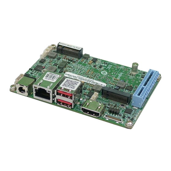
1.1 Introduction Figure 1-1: HYPER-EHL It is powered The HYPER-EHL series is a single bard computer in Pico-ITX form factor. by Intel® Celeron® J6412 on-board SoC or Intel® Celeron® N6210 on-board SoC. supports on-board 4GB 3200 MHz LPDDR4X (system max. 8GB). -
Page 14: Features
HYPER-EHL 1.2 Features Some of the HYPER-EHL motherboard features are listed below: ▪ Support Intel® Atom® x6000 series / Pentium® / Celeron® processor (Elkhart Lake platform) Intel® Celeron® J6412 on-board SoC (up to 2.6GHz, quad-core, 1.5M cache, TDP=10W) Intel® Celeron® N6210 on-board SoC (up to 2.6GHz, dual-core, 1.5M cache, TDP=6.5W) -
Page 15: Connectors
HYPER-EHL 1.3 Connectors The connectors on the HYPER-EHL are shown in the figure below. Figure 1-2: Connectors Page 15... -
Page 16: Dimensions
HYPER-EHL 1.4 Dimensions The main dimensions of the HYPER-EHL are shown in the diagram below. Figure 1-3: HYPER-EHL Dimensions (mm) Page 16... -
Page 17: Data Flow
HYPER-EHL 1.5 Data Flow Figure 1-4 shows the data flow between the system chipset, the CPU and other components installed on the motherboard. Figure 1-4: Data Flow Diagram Page 17... -
Page 18: Technical Specifications
HYPER-EHL 1.6 Technical Specifications The HYPER-EHL technical specifications are listed below. 747H Specification/Model HYPER-EHL Pico-ITX Form Factor Support Intel® Atom® x6000 series / Pentium® / Celeron® processor (Elkhart Lake platform) Intel® Celeron® J6412 on-board SoC CPU Supported (up to 2.6GHz, quad-core, 1.5M cache, TDP=10W) Intel®... -
Page 19: Table 1-1: Hyper-Ehl Specifications
EuP mode enabled) Operating 0ºC ~ 60ºC Temperature -30ºC ~ 70ºC Storage Temperature 5% ~ 95% (non-condensing) Operating Humidity Physical Specifications 100 mm x 72 mm Dimensions Weight (GW/NW) 600g / 250g Table 1-1: HYPER-EHL Specifications Page 19... -
Page 20: Packing List
HYPER-EHL Chapter Packing List Page 20... -
Page 21: Anti-Static Precautions
Only handle the edges of the PCB: Don't touch the surface of the motherboard. Hold the motherboard by the edges when handling. 2.2 Unpacking Precautions When the HYPER-EHL is unpacked, please do the following: ▪ Follow the anti-static guidelines above. -
Page 22: Packing List
If any of the components listed in the checklist below are missing, do not proceed with the installation. Contact the IEI reseller or vendor the HYPER-EHL was purchased from or contact an IEI sales representative directly by sending an email to sales@ieiworld.com. -
Page 23: Optional Items
HYPER-EHL 2.4 Optional Items The following are optional components which may be separately purchased: Item and Part Number Image Dual-port USB cable with bracket, 300mm, p=2.0 (P/N: CB-USB02A-RS) SATA power cable, MOLEX 5264-4P to SATA15P (P/N: 32102-000100-200-RS) PCIe x4 to two PCIe x2 riser card for HYPER on the left... -
Page 24: Table 2-2: Optional Items
HYPER-EHL Item and Part Number Image eDP to eDP converter board (for IEI iDPM slot) (P/N: iDPM-eDP-R10) eDP to LVDS converter board (for IEI iDPM slot) (P/N: iDPM-LVDS-R10) Table 2-2: Optional Items Page 24... -
Page 25: Connectors
HYPER-EHL Chapter Connectors Page 25... -
Page 26: Peripheral Interface Connectors
HYPER-EHL 3.1 Peripheral Interface Connectors This chapter details all the peripheral interface connectors. 3.1.1 HYPER-EHL Layout The figures below show all the peripheral interface connectors. Figure 3-1: Peripheral Interface Connectors 3.1.2 Peripheral Interface Connectors The table below lists all the connectors on the board. -
Page 27: External Interface Panel Connectors
HYPER-EHL Connector Type Label BuzzerConnector 2-pin wafer Digital I/O Connector 10-pin wafer DIO1 Flash SPI ROM Connector 6-pin wafer JBIOS1 I2C Connector 4-pin wafer I2C1 iSATA 6Gb/s Connector 20-pin SATA connector ISATA Power Button Connector 2-pin header PWR_BTN1 Reset Button Connector... -
Page 28: Internal Peripheral Connectors
HYPER-EHL 3.2 Internal Peripheral Connectors The section describes all of the connectors on the HYPER-EHL. 3.2.1 Battery Connector CAUTION: Risk of explosion if battery is replaced by an incorrect type. Only certified engineers should replace the on-board battery. Dispose of used batteries according to instructions and local regulations. -
Page 29: Figure 3-2: Battery Connector Location
HYPER-EHL Figure 3-2: Battery Connector Location Description Description VBATT Table 3-3: Battery Connector Pinouts Page 29... -
Page 30: At/Atx Power Mode Setting
HYPER-EHL 3.2.2 AT/ATX Power Mode Setting CN Label: J_ATX_AT1 CN Type: 3-pin switch CN Location: Figure 3-3 CN Pinouts: See Table 3-4 The AT/ATX power mode selection is made through the AT/ATX power mode switch. Figure 3-3: AT/ATX Power Mode Switch Location... -
Page 31: Digital I/O Connector
HYPER-EHL 3.2.3 Digital I/O Connector CN Label: DIO1 CN Type: 10-pin wafer, p=2.0 mm CN Location: See Figure 3-4 CN Pinouts: See Table 3-5 The Digital I/O connector provides programmable input and output for external devices. Figure 3-4: Digital I/O Connector Location... -
Page 32: Clear Cmos Button
HYPER-EHL 3.2.4 Clear CMOS Button CN Label: J_CMOS1 CN Type: Button CN Location: See Figure 3-5 CN Pinouts: See Table 3-6 The J_CMOS1 is used to Clear CMOS Setup. Figure 3-5: Clear CMOS Jumper Location Description Keep CMOS Setup (Normal Operation) -
Page 33: I 2 C Connector
HYPER-EHL 3.2.5 I C Connector CN Label: I2C1 CN Type: 4-pin wafer, p=1.25 mm CN Location: See Figure 3-6 CN Pinouts: See Table 3-7 The I C connector is used to connect I C-bus devices to the mainboard. Figure 3-6: I... -
Page 34: Internal Usb 2.0 Connectors
HYPER-EHL 3.2.6 Internal USB 2.0 Connectors CN Label: USB2-1 CN Type: 8-pin header, p=2.54 mm CN Location: See Figure 3-7 CN Pinouts: See Table 3-8 The Internal USB 2.0 connectors connect to USB 2.0 devices. Figure 3-7: Internal USB 2.0 Connector Location... -
Page 35: M-Key Slot
HYPER-EHL 3.2.7 M.2 M-key Slot CN Label: M2_1 CN Type: M.2 M-key slot CN Location: See Figure 3-8 CN Pinouts: See Table 3-9 The M.2 2242 slot is keyed in the M position. Figure 3-8: M.2 M-key Slot Location Description Description +V3.3A... -
Page 36: Table 3-9: M.2 M-Key Connector Pinouts
HYPER-EHL Description Description PCIE_RX7- PCIE_RX7+ USB+ PCIE_TX7- USB- PCIE_TX7+ MKEY_SSD_SLP M2_I2C_CLK PCIE_RX6- M2_I2C_DATA PCIE_RX6+ PCIE_TX6- PCIE_TX6+ BUF_PLT_RST CLK_M2_B- PCIE_WAKE# CLK_M2_B+ Module Key Module Key Module Key Module Key Module Key Module Key Module Key Module Key +V3.3A +V3.3A +V3.3A +V3.3A Table 3-9: M.2 M-key Connector Pinouts... -
Page 37: Iei Idpm Slot
HYPER-EHL 3.2.8 IEI iDPM Slot CN Label: IDPM CN Type: IDPM slot CN Location: See Figure 3-9 CN Pinouts: See Table 3-10 The iDPM slot is only for IEI eDP/LVDS/VGA module Figure 3-9: iDPM Slot Location Description Description +3.3V +3.3V NGFF2_ACT_N +3.3V... -
Page 38: Table 3-10: Idpm Connector Pinouts
HYPER-EHL Description Description PCIE_18_RX_DN PCIE_18_RX_DP PCIE_18_TX_DN18 PCIE_18_TX_DP18 M_2_SATA_SLP PCIE_17_RX_DN PCIE_17_RX_DP PCIE_17_TX_DN17 PCIE_17_TX_DP17 PERST_N SRCCLKREQB_15_N PCIE_SRC15_DN PCIE_SRC15_DP +3.3V +3.3V +3.3V Table 3-10: iDPM Connector Pinouts Page 38... -
Page 39: Pcie X4 Slot
HYPER-EHL 3.2.9 PCIe x4 Slot CN Label: IP2EHL_XC CN Type: PCIe x4 slot CN Location: See Figure 3-10 The PCIe x4 expansion card slots are for PCIe x4 expansion cards. Figure 3-10: PCIe x4 Slot Location 3.2.10 Power Button Connector... -
Page 40: Reset Button Connector
HYPER-EHL Figure 3-11: Power Button Connector Location 3.2.11 Reset Button Connector CN Label: RST_BTN1 CN Type: 2-pin wafer, p=2.00 mm CN Location: See Figure 3-12 The reset button connector is connected to a reset switch on the system chassis allows users to reboot the system when the system is turned on. -
Page 41: Isata 6Gb/S Connectors
HYPER-EHL 3.2.12 iSATA 6Gb/s Connectors CN Label: ISATA CN Type: 20-pin SATA connector CN Location: See Figure 3-13 CN Pinouts: See Table 3-11 The iSATA drive connector is connected to a SATA device via a cable defined by IEI. The iSATA drive transfers data at speeds as high as 6Gb/s. -
Page 42: Rs-232/422/485 Serial Port Connector
HYPER-EHL 3.2.13 RS-232/422/485 Serial Port Connector CN Label: COM1 CN Type: 9-pin header, p=2.54 mm CN Location: See Figure 3-14 CN Pinouts: See Table 3-12 /422/485 Each of these connectors provides RS-232 communications. Figure 3-14: RS-232/422/485 Connector Location Description Description... -
Page 43: Buzzer Connector
HYPER-EHL 3.2.14 Buzzer Connector CN Label: CN Type: 2-pin wafer, p=1.25 mm CN Location: See Figure 3-15 CN Pinouts: See Table 3-13 The buzzer connector is connected with the buzzer to give a beep warning when the motherboard goes wrong. -
Page 44: Flash Spi Rom Connector
HYPER-EHL 3.2.15 Flash SPI ROM Connector CN Label: JBIOS1 CN Type: 6-pin wafer, p=1.25 mm CN Location: See Figure 3-16 CN Pinouts: See Table 3-14 The Flash SPI ROM connector is used to flash the BIOS. Figure 3-16: Flash SPI ROM Connector Location... -
Page 45: External Peripheral Interface Connector Panel
HYPER-EHL 3.3 External Peripheral Interface Connector Panel The figure below shows the external peripheral interface connector (EPIC) panel. The EPIC panel consists of the following: Figure 3-17: External Peripheral Interface Connector 3.3.1 External 12V DC Input Jack CN Label: DCIN1... -
Page 46: External 2.5Gbe Rj-45 Connector
HYPER-EHL 3.3.2 External 2.5GbE RJ-45 Connector CN Label: LAN1 CN Type: RJ45 CN Location: See Figure 3-19 CN Pinouts: See Table 3-16 The LAN connector connects to a local network. Figure 3-19: LAN Connector DESCRIPTION DESCRIPTION LAN1_MDI0P LAN1_MDI2P LAN1_MDI0N LAN1_MDI2N... -
Page 47: External Hdmi Combo Connector
HYPER-EHL 3.3.3 External HDMI Combo Connector CN Label: HDMI CN Type: HDMI CN Location: See Figure 3-20 CN Pinouts: See Table 3-18 The external HDMI connector can connect to an HDMI device. Figure 3-20: External HDMI Connector Location Description Description... -
Page 48: External Dual Usb 3.2 Gen2 10Gb/S Connector
HYPER-EHL 3.3.4 External Dual USB 3.2 Gen2 10Gb/s Connector CN Label: USB1 CN Type: USB 3.2 CN Location: See Figure 3-21 CN Pinouts: See Table 3-19 The external dual USB 3.2 Gen 2 connector can be connected to USB2.0 or USB 3,2 devices. -
Page 49: Installation
HYPER-EHL Chapter Installation Page 49... -
Page 50: Anti-Static Precautions
Electrostatic discharge (ESD) can cause serious damage to electronic components, including the HYPER-EHL. Dry climates are especially susceptible to ESD. It is therefore critical that whenever the HYPER-EHL or any other electrical component is handled, the following anti-static precautions are strictly adhered to. -
Page 51: Module Installation
Allow screws to come in contact with the PCB circuit, connector pins, or its components. 4.3 M.2 Module Installation The HYPER-EHL provide two ways to install the M.2 expansion card. One is using screw, and the other is using the retainer. Please follow the steps below. Page 51... -
Page 52: Figure 4-1: Inserting The M.2 Module Into The Slot At An Angle
HYPER-EHL Mode One: Using screw Step 1: Locate the M.2 module slot. See Chapter 3. Step 2: Remove the retention screw secured on the motherboard. Step 3: Line up the notch on the module with the notch on the slot. Slide the M.2 module into the socket at an angle of about 20º... -
Page 53: Figure 4-3: Press The Retainer
HYPER-EHL Mode Two: Using the Retainer Step 1: Press the retainer down as shown below. (See Figure 4-3) Figure 4-3: Press the Retainer Step 2: Line up the notch on the M.2 module with the notch on the slot. Slide the M.2 module into the socket at an angle of about 20º. -
Page 54: Riser Card Installation
Step 1 to release the M.2 module. (See Figure 4-3) 4.4 Riser Card Installation The HYPER-EHL features a PCIe x4 (x4 signal) slot, which is a new design of the motherboard to expand functionality. By installing an IEI-developed riser card into the PCIe slot, the x4 signal is divided into x4 or x2+x2 or 1+x1+x1+x1 slots, offering great configuration flexibility and expandability. -
Page 55: The Inwards-Facing Riser Card
HYPER-EHL 4.4.1 The inwards-facing riser card The inwards-facing riser card (P/N: HPR-R2S-R10, HPR-R4S-R10), although lower in height, is able to provide better spacing to ensure expansion cards to run at a low temperature. It is ideal for the chassis that is wide enough for the expansion card to be placed. -
Page 56: The Outwards-Facing Riser Card
HYPER-EHL Figure 4-7: Inwards Riser Card Installation Example (P/N: HPR-R4S-R10) 4.4.2 The outwards-facing riser card The inwards-facing riser card (P/N: NWR-L2S- R10, NWR-L4S- R10) is designed with higher height to keep a decent space between the expansion cards and the motherboard. -
Page 57: Figure 4-9: Outwards Riser Card Installation Example (P/N: Nwr-L4S-R10)
HYPER-EHL Figure 4-9: Outwards Riser Card Installation Example (P/N: NWR-L4S-R10) Page 57... -
Page 58: Software Installation
HYPER-EHL 4.5 Software Installation All the drivers for the HYPER-EHL are available on IEI Resource Download Center (https://download.ieiworld.com). Type HYPER-EHL and press Enter to find all the relevant software, utilities, and documentation. Figure 4-10: IEI Resource Download Center 4.6 Driver Download To download drivers from IEI Resource Download Center, follow the steps below. - Page 59 HYPER-EHL Step 3: Click the driver file name on the page and you will be prompted with the following window. You can download the entire ISO file ( ), or click the small arrow to find an individual driver and click the file name to download (...
-
Page 60: Bios
HYPER-EHL Chapter BIOS Page 60... -
Page 61: Introduction
HYPER-EHL 5.1 Introduction The BIOS is programmed onto the BIOS chip. The BIOS setup program allows changes to certain system settings. This chapter outlines the options that can be changed. NOTE: Some of the BIOS options may vary throughout the life cycle of the product and are subject to change without prior notice. -
Page 62: Using Setup
HYPER-EHL 5.1.2 Using Setup The BIOS Setup menu can be navigated by using a keyboard or a touchscreen. 5.1.2.1 Keyboard Navigation For keyboard navigation, use the navigation keys shown in Table 5-1. Function Up arrow Move to previous item Down arrow... -
Page 63: Touch Navigation
HYPER-EHL 5.1.2.2 Touch Navigation For touchscreen navigation, use the on-screen navigation keys shown below. On-screen Button Function Previous Values Load the last value you set. Optimized Defaults Load the factory default values in order to achieve the best performance. Back Return to the previous menu. -
Page 64: Getting Help
HYPER-EHL 5.1.3 Getting Help When F1 is pressed a small help window describing the appropriate keys to use and the possible selections for the highlighted item appears. To exit the Help Window, press the key. 5.1.4 Unable to Reboot after Configuration Changes If the computer cannot boot after changes to the system configuration is made, CMOS defaults. -
Page 65: Main
HYPER-EHL 5.2 Main The Main BIOS menu (BIOS Menu 2) appears when the BIOS Setup program is entered. The Main menu gives an overview of the basic system information. BIOS Menu 1: Main (1/3) BIOS Menu 2: Main (2/3) Page 65... - Page 66 HYPER-EHL BIOS Menu 3: Main (3/3) ➔ BIOS Information The BIOS Information lists a brief summary of the BIOS. The fields in BIOS Information cannot be changed. The items shown in the system overview include: ▪ BIOS Vendor: Installed BIOS vendor ▪...
- Page 67 HYPER-EHL ▪ Speed: Displays the Processor Speed ▪ ID: Displays the Processor ID ➔ PCH Information The PCH Information lists a brief summary of the PCH. The fields in PCH Information cannot be changed. The items shown in the system overview include: ▪...
-
Page 68: Advanced
HYPER-EHL 5.3 Advanced Use the Advanced menu (BIOS Menu 4) to configure the CPU and peripheral devices through the following sub-menus: WARNING! Setting the wrong values in the sections below may cause the system to malfunction. Make sure that the settings made are compatible with the hardware. -
Page 69: Cpu Configuration
HYPER-EHL 5.3.1 CPU Configuration Use the CPU Configuration menu (BIOS Menu 5) to view detailed CPU specifications or enable the Intel Virtualization Technology. BIOS Menu 5: CPU Configuration (1/3) Page 69... - Page 70 HYPER-EHL BIOS Menu 6: CPU Configuration (2/3) BIOS Menu 7: CPU Configuration (3/3) Page 70...
- Page 71 HYPER-EHL ➔ Intel (VMX) Virtualization Technology [Enabled] Use the Intel (VMX) Virtualization Technology option to enable or disable virtualization on the system. When combined with third party software, Intel® Virtualization technology allows several OSs to run on the same system at the same time.
- Page 72 HYPER-EHL ➔ Tcc Activation Offset [0] Use the Tcc Activation Offset option to set Tcc activation temprature at which the Thermal Control Circuit must be activated. Tcc will be activated at: Tcc Activation Temp-Tcc Activation Offset. Tcc Activation Offset range is 0 to 63.
-
Page 73: Trusted Computing
HYPER-EHL 5.3.2 Trusted Computing Use the Trusted Computing menu (BIOS Menu 8) to configure settings related to the Trusted Computing Group (TCG) Trusted Platform Module (TPM). BIOS Menu 8: PCH-FW Configuration ➔ Security Device Support [Enable] Use the Security Device Support option to enable or disable BIOS support for security device. -
Page 74: It5571 Super Io Configuration
HYPER-EHL 5.3.3 IT5571 Super IO Configuration Use the IT5571 Super IO Configuration menu (BIOS Menu 9) to set or change the configurations for serial port. BIOS Menu 9: IT5571 Super IO Configuration Page 74... -
Page 75: Serial Port 1 Configuration
HYPER-EHL 5.3.3.1 Serial Port 1 Configuration Use the Serial Port 1 Configuration menu (BIOS Menu 10) to configure the serial port. BIOS Menu 10: Serial Port 1 Configuration Menu ➔ Serial Port [Enabled] Use the Serial Port option to enable or disable the serial port. -
Page 76: It5571 H/W Monitor
HYPER-EHL ➔ Device Mode [RS232] Use the Device Mode option to change the serial port mode. ➔ RS232 The serial port mode is RS-232 EFAULT RS422 with Register The serial port mode is RS-422 RS485 with Register The serial port mode is RS-485 5.3.4 IT5571 H/W Monitor... -
Page 77: Rtc Wake Settings
HYPER-EHL ▪ System Temperatures: CPU Temperature System Temperature ▪ Voltages: CPU_CORE +12V +DDR +3.3V 5.3.5 RTC Wake Settings The RTC Wake Settings menu (BIOS Menu 12) configures RTC wake event. BIOS Menu 12: RTC Wake Settings (1/2) Page 77... - Page 78 HYPER-EHL BIOS Menu 13: RTC Wake Settings (2/2) ➔ Wake system with Fixed Time [Enabled] Use the Wake system with Fixed Time option to enable or disable the system wake on alarm event. ➔ Disabled The real time clock (RTC) cannot generate a wake event ➔...
-
Page 79: Serial Port Console Redirection
HYPER-EHL 5.3.6 Serial Port Console Redirection The Serial Port Console Redirection menu (BIOS Menu 14) allows the console redirection options to be configured. Console Redirection allows users to maintain a system remotely by re-directing keyboard input and text output through the serial port. -
Page 80: Console Redirection Settings
HYPER-EHL 5.3.6.1 Console Redirection Settings The following options are available in the Console Redirection Settings submenu (BIOS Menu 15) when the COM Console Redirection (for COM1) option is enabled. BIOS Menu 15: COM Console Redirection Settings Terminal Type [ANSI] ➔... - Page 81 HYPER-EHL ➔ 9600 Sets the serial port transmission speed at 9600. ➔ 19200 Sets the serial port transmission speed at 19200. ➔ 38400 Sets the serial port transmission speed at 38400. ➔ 57600 Sets the serial port transmission speed at 57600.
-
Page 82: Nvme Configuration
HYPER-EHL ➔ Sets the number of stop bits at 2. 5.3.7 NVMe Configuration Use the NVMe Configuration (BIOS Menu 16) menu to display the NVMe controller and device information. BIOS Menu 16: NVMe Configuration Page 82... -
Page 83: Chipset
HYPER-EHL 5.4 Chipset Use the Chipset menu (BIOS Menu 17) to access the PCH IO and System Agent (SA) configuration menus. WARNING! Setting the wrong values for the Chipset BIOS selections in the Chipset BIOS menu may cause the system to malfunction. -
Page 84: System Agent (Sa) Configuration
HYPER-EHL 5.4.1 System Agent (SA) Configuration Use the System Agent (SA) Configuration menu (BIOS Menu 18) to configure the System Agent (SA) parameters. BIOS Menu 18: System Agent (SA) Configuration ➔ VT-d [Enabled] Use the VT-d option to enable or disable the VT-d capability. -
Page 85: Memory Configuration
HYPER-EHL 5.4.1.1 Memory Configuration Use the Memory Configuration submenu (BIOS Menu 19) to view memory information. BIOS Menu 19: Memory Configuration Page 85... -
Page 86: Graphics Configuration
HYPER-EHL 5.4.1.2 Graphics Configuration Use the Graphics Configuration (BIOS Menu 20) menu to configure the video device connected to the system. BIOS Menu 20: Graphics Configuration ➔ Primary Display [Auto] Use the Primary Display option to select the primary graphics controller the system uses. - Page 87 HYPER-EHL Graphics option should be set to Enabled and the above Primary Display option should be set to IGFX. ➔ Auto Auto mode ➔ Disabled Disables IGFX. ➔ Enabled Default Enables IGFX. ➔ DVMT Pre-Allocated [160M] Use the DVMT Pre-Allocated option to set the amount of system memory allocated to the integrated graphics processor when the system boots.
-
Page 88: Bios Menu 21: Lcd Control
HYPER-EHL ➔ LCD Control BIOS Menu 21: LCD Control ➔ LVDS Backlight PWM mode [Invert] Use the LVDS Backlight PWM mode option to specify a PWM mode for LVDS backlight control. ➔ Invert Default Set to invert LVDS Backlight ➔... -
Page 89: Pch-Io Configuration
HYPER-EHL 5.4.2 PCH-IO Configuration Use the PCH-IO Configuration menu (BIOS Menu 22) to configure the PCH parameters. BIOS Menu 22: PCH-IO Configuration Auto Power Button Function [Disabled (ATX)] ➔ Use the Auto Power Button Function BIOS option to show the power mode state. Use the J_ATX_AT1 to switch the AT/ATX power mode. -
Page 90: Pci Express Configuration
HYPER-EHL ➔ Enabled Power saving function is enabled. It will reduce power consumption when the system is off. ➔ USB Power state [+5VDUAL] Use the USB Power state option to enable or disable the USB Power. ➔ +5VDUAL USB Power is on. -
Page 91: Pcie Root Port Setting
HYPER-EHL 5.4.2.1.1 PCIe Root Port Setting Use the PCIEX4_1X4, M2_B1 submenu (BIOS Menu 24) to configure the PCIe Root Port Setting. BIOS Menu 24: PCIe Slot Configuration Submenu ➔ PCIe Speed [Auto] Use the PCIe Speed option to specify the PCI Express port speed. Configuration options are listed below. -
Page 92: Sata Configuration
HYPER-EHL ➔ Detect Non-Compliance Device [Disabled] Use the Detect Non-Compliance Device option to configure whether to detect if a non- compliance PCI Express device is connected to the PCI Express port. ➔ Disabled Do not detect if a non-compliance PCI Express EFAULT device is connected to the PCI Express port. - Page 93 HYPER-EHL ➔ Disabled Disable the SATA device. ➔ Enabled EFAULT Enable the SATA device. ➔ SATA Mode Selection [AHCI] Use the SATA Mode Selection option to determine how the SATA devices operate. ➔ AHCI EFAULT Configures SATA devices as AHCI device.
-
Page 94: Security
HYPER-EHL 5.5 Security Use the Security menu (BIOS Menu 27) to set system and user passwords. BIOS Menu 26: Security (1/2) Page 94... - Page 95 HYPER-EHL BIOS Menu 27: Security (2/2) ➔ Administrator Password Use the Administrator Password to set or change an administrator password. ➔ User Password Use the User Password to set or change a user password. Page 95...
-
Page 96: Boot
HYPER-EHL 5.6 Boot Use the Boot menu (BIOS Menu 28) to configure system boot options. BIOS Menu 28: Boot 5.6.1 Boot Configuration ➔ Quiet Boot [Enabled] Use the Quiet Boot BIOS option to select the screen display when the system boots. -
Page 97: Boot Option Priorities
HYPER-EHL ➔ Disabled Ignore all PXE Option ROMs EFAULT ➔ Enabled Load PXE Option ROMs. ➔ Option ROM Messages [Force BIOS] Use the Option ROM Messages option to set the Option ROM display mode. ➔ Force Sets display mode to force BIOS. -
Page 98: Save & Exit
HYPER-EHL 5.7 Save & Exit Use the Save & Exit menu (BIOS Menu 29) to load default BIOS values, optimal failsafe values and to save configuration changes. BIOS Menu 29: Save & Exit ➔ Save Changes and Reset Use the Save Changes and Reset option to save the changes made to the BIOS options and reset the system. - Page 99 HYPER-EHL ➔ Save as User Defaults Use the Save as User Defaults option to save the changes done so far as user defaults. ➔ Restore User Defaults Use the Restore User Defaults option to restore the user defaults to all the setup options.
-
Page 100: A Regulatory Compliance
HYPER-EHL Appendix Regulatory Compliance Page 100... - Page 101 HYPER-EHL DECLARATION OF CONFORMITY This equipment has been tested and found to comply with specifications for CE marking. If the user modifies and/or installs other devices in the equipment, the CE conformity declaration may no longer apply. FCC WARNING This equipment complies with Part 15 of the FCC Rules. Operation is subject to the...
-
Page 102: B Product Disposal
HYPER-EHL Appendix Product Disposal Page 102... - Page 103 HYPER-EHL CAUTION: Risk of explosion if battery is replaced by an incorrect type. Only certified engineers should replace the on-board battery. Dispose of used batteries according to instructions and local regulations. ▪ Outside the European Union–If you wish to dispose of used electrical and electronic products outside the European Union, please contact your local authority so as to comply with the correct disposal method.
-
Page 104: Cbios Options
HYPER-EHL Appendix BIOS Options Page 104... - Page 105 HYPER-EHL Below is a list of BIOS configuration options in the BIOS chapter. ➔ BIOS Information .........................66 ➔ Processor Information ......................66 ➔ PCH Information ........................67 ➔ System Date [xx/xx/xx] ......................67 ➔ System Time [xx:xx:xx] .......................67 ➔ Intel (VMX) Virtualization Technology [Enabled] ..............71 ➔...
- Page 106 HYPER-EHL ➔ Auto Power Button Function [Disabled (ATX)] ..............89 ➔ Power Saving Function (ERP) [Disabled] ................89 ➔ USB Power state [+5VDUAL] ....................90 ➔ PCIe Speed [Auto] ........................91 ➔ Detect Non-Compliance Device [Disabled] ...............92 ➔ SATA Controller(s) [Enabled] .....................92 ➔ SATA Mode Selection [AHCI] ....................93 ➔...
-
Page 107: D Watchdog Timer
HYPER-EHL Appendix Watchdog Timer Page 107... - Page 108 HYPER-EHL NOTE: The following discussion applies to DOS environment. Contact IEI support or visit the IEI website for specific drivers for other operating systems. The Watchdog Timer is provided to ensure that standalone systems can always recover from catastrophic conditions that cause the CPU to crash. This condition may have occurred by external EMIs or a software bug.
- Page 109 HYPER-EHL NOTE: When exiting a program it is necessary to disable the Watchdog Timer, otherwise the system resets. EXAMPLE PROGRAM: ; INITIAL TIMER PERIOD COUNTER W_LOOP: AX, 6F02H ;setting the time-out value BL, 30 ;time-out value is 48 seconds ; ADD THE APPLICATION PROGRAM HERE EXIT_AP, 1 ;is the application over?
-
Page 110: E Error Beep Code
HYPER-EHL Appendix Error Beep Code Page 110... -
Page 111: Pei Beep Codes
HYPER-EHL E.1 PEI Beep Codes Number of Beeps Description Memory not Installed Memory was installed twice (InstallPeiMemory routine in PEI Core called twice) Recovery started DXEIPL was not found DXE Core Firmware Volume was not found Recovery failed S3 Resume failed Reset PPI is not available E.2 DXE Beep Codes... -
Page 112: F Hazardous Materials Disclosure
HYPER-EHL Appendix Hazardous Materials Disclosure Page 112... -
Page 113: Rohs Ii Directive (2015/863/Eu)
HYPER-EHL F.1 RoHS II Directive (2015/863/EU) The details provided in this appendix are to ensure that the product is compliant with the RoHS II Directive (2015/863/EU). The table below acknowledges the presences of small quantities of certain substances in the product, and is applicable to RoHS II Directive (2015/863/EU). -
Page 114: China Rohs
HYPER-EHL F.2 China RoHS 此附件旨在确保本产品符合中国 RoHS 标准。以下表格标示此产品中某有毒物质的含量符 合中国 RoHS 标准规定的限量要求。 本产品上会附有”环境友好使用期限”的标签,此期限是估算这些物质”不会有泄漏或突变”的 年限。本产品可能包含有较短的环境友好使用期限的可替换元件,像是电池或灯管,这些 元件将会单独标示出来。 部件名称 有毒有害物质或元素 壳体 印刷电路板 金属螺帽 电缆组装 风扇组装 电力供应组装 电池 O: 表示该有毒有害物质在该部件所有物质材料中的含量均在 SJ/T11364-2014 與 GB/T26572- 2011 标准规定的限量要求以下。 X: 表示该有毒有害物质至少在该部件的某一均质材料中的含量超出 SJ/T11364-2014 與 GB/T26572-2011 标准规定的限量要求。 Page 114...
Need help?
Do you have a question about the HYPER-EHL and is the answer not in the manual?
Questions and answers