Table of Contents
Advertisement
Quick Links
Advertisement
Table of Contents

Related Manuals for IEI Technology DRPC-140-EHL Series


Summary of Contents for IEI Technology DRPC-140-EHL Series
- Page 1 DRPC-140-EHL MODEL: DRPC-140-EHL Series Fanless embedded system, Intel® Celeron® J6412 2.0GHz (up to 2.6GHz, 4-Core, TDP 10W), four RS-232/422/485, four USB 3.2, two HDMI, two 2.5GbE LAN, 12-bit DIO, CAN-Bus, 12~24V DC and RoHS User Manual Page I Rev. 1.00 – October 25, 2023...
- Page 2 DRPC-140-EHL Revision Date Version Changes Oct. 25, 2023 1.00 Initial release Page II [MODEL NAME]...
- Page 3 DRPC-140-EHL Copyright COPYRIGHT NOTICE The information in this document is subject to change without prior notice in order to improve reliability, design and function and does not represent a commitment on the part of the manufacturer. In no event will the manufacturer be liable for direct, indirect, special, incidental, or consequential damages arising out of the use or inability to use the product or documentation, even if advised of the possibility of such damages.
- Page 4 DRPC-140-EHL Manual Conventions WARNING Warnings appear where overlooked details may cause damage to the equipment or result in personal injury. Warnings should be taken seriously. CAUTION Cautionary messages should be heeded to help reduce the chance of losing data or damaging the product. NOTE These messages inform the reader of essential but non-critical information.
-
Page 5: Table Of Contents
DRPC-140-EHL Table of Content 1 INTRODUCTION ......................1 1.1 O ........................2 VERVIEW 1.2 F ........................2 EATURES 1.3 T ..................3 ECHNICAL PECIFICATIONS 1.4 F ......................4 RONT ANEL 1.5 T ......................... 5 ANEL 1.6 P ....................6 HYSICAL IMENSIONS 2 UNPACKING ......................... - Page 6 DRPC-140-EHL 3.8.5 DB-9 RS-232/422/485 Serial Port Connection ..........24 3.8.6 USB Connectors ....................25 3.9 P ................26 OWERING FF THE YSTEM 3.10 A ....................27 VAILABLE RIVERS 3.10.1 Driver Download ................... 28 4 SYSTEM MOTHERBOARD ..................30 4.1 L ........................
- Page 7 DRPC-140-EHL 5.1.3 Getting Help ..................... 58 5.1.4 Unable to Reboot after Configuration Changes ..........58 5.1.5 BIOS Menu Bar ....................58 5.2 M ........................59 5.3 A ....................... 62 DVANCED 5.3.1 CPU Configuration ..................63 5.3.2 Trusted Computing ................... 67 5.3.3 RTC Wake settings ....................
- Page 8 DRPC-140-EHL A.2 M ............102 AINTENANCE AND LEANING RECAUTIONS A.2.1 Maintenance and Cleaning ................102 A.2.2 Cleaning Tools ....................102 Page VIII [MODEL NAME]...
- Page 9 DRPC-140-EHL List of Figures Figure 1-1: DRPC-140-EHL Series ....................2 Figure 1-2: Front Panel ........................4 Figure 1-3: Top Panel ........................5 Figure 1-4: Physical Dimensions ....................6 Figure 3-1: Remove the Cover .....................13 Figure 3-2: Open the handles of the Memory Slot ..............14 Figure 3-3: Insert the Memory Module..................14...
- Page 10 DRPC-140-EHL Figure 4-5: Case Open Circuit Setting Locations ..............37 Figure 4-6: Flash Descriptor Override Setting Jumper Locations ..........38 Figure 4-7: Battery Connector Location ..................40 Figure 4-8: Buzzer Connector Location ..................41 Figure 4-9: DDR4 SO-DIMM Socket Location ................42 Figure 4-10: Mini SATA Connectors Location ................43 Figure 4-11: SPI TPM Connectors Location ................44 Figure 4-12: Flash SPI ROM Connector Location ..............45 Figure 4-13: I²...
- Page 11 DRPC-140-EHL List of Tables Table 1-1: Technical Specifications ....................4 Table 3-1: LAN1-3 2.5GbE RJ-45 Ethernet Connector LEDs ............22 Table 3-2: Power Connector Pinouts ..................23 Table 3-3: RS-232/422/485 (COM1-4) Connector Pinouts ............24 Table 4-1: Peripheral Interface Connectors ................32 Table 4-2: AT/ATX Power Mode Switch Pinouts ................33 Table 4-3: Reset Button Connector Pinouts ................34 Table 4-4: Digital IO Connector Pinouts ..................35 Table 4-5: CAN Bus Connector Pinouts ..................35...
- Page 12 DRPC-140-EHL BIOS Menus BIOS Menu 1: Main (1/2) .......................59 BIOS Menu 2: Main (2/2) .......................59 BIOS Menu 3: Advanced ......................62 BIOS Menu 4: CPU Configuration (1/3)..................63 BIOS Menu 5: CPU Configuration (2/3)..................63 BIOS Menu 6: CPU Configuration (3/3)..................64 BIOS Menu 7: Trusted Computing ....................67 BIOS Menu 8: RTC Wake Settings....................68 BIOS Menu 9: IT5571 Super IO Configuration ................69 BIOS Menu 10: Serial Port 1 Configuration Menu ..............70...
- Page 13 DRPC-140-EHL BIOS Menu 31: Save & Exit ......................96 Page XIII [MODEL NAME]...
-
Page 15: Introduction
DRPC-140-EHL Chapter Introduction Page 1... -
Page 16: Overview
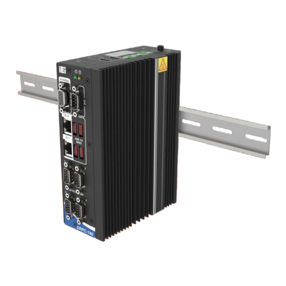
1.1 Overview Figure 1-1: DRPC-140-EHL Series The DRPC-140-EHL series embedded system adopts Intel® Elkhart Lake processor with 8GB memory pre-installed (up to 32GB), and including two HDMI, two 2.5 GbE LAN ports, four USB ports, four RS-232 /422/485 (DB-9), two CAN-bus (DB9 with 2.5kV isolation), It is designed for harsh environment applications, and supports DIN rail mounting method. -
Page 17: Technical Specifications
DRPC-140-EHL 1.3 Technical Specifications The DRPC-140-EHL Series technical specifications are listed in (Table 1-1). Model Name DRPC-140-EHL Black Color 58.75 x 130 x 174 Dimension( WxDxH)(mm) Chassis Fanless System Fan Extruded aluminum alloy Chassis Construction Intel® Celeron® J6412 2.0GHz (up to 2.6GHz, quad-core, TDP 10W) -
Page 18: Front Panel
CE, FCC, UKCA Safety / EMC Programmable 1~255 sec/min Watchdog timer Microsoft® Windows® 10/11, Linux Supported OS Table 1-1: Technical Specifications 1.4 Front Panel The front panel of the DRPC-140-EHL Series has the following features. Figure 1-2: Front Panel Page 4... -
Page 19: Top Panel
DRPC-140-EHL 1.5 Top Panel An overview of the DRPC-140-EHL top panel is bellow Figure 1-3: Top Panel Page 5... -
Page 20: Physical Dimensions
DRPC-140-EHL 1.6 Physical Dimensions The physical dimensions of the DRPC-140-EHL Series are shown in (Figure 1-4). Figure 1-4: Physical Dimensions Page 6... -
Page 21: Unpacking
DRPC-140-EHL Chapter Unpacking Page 7... -
Page 22: Anti-Static Precautions
DRPC-140-EHL Series and severe injury to the user. Electrostatic discharge (ESD) can cause serious damage to electronic components, including the DRPC-140-EHL Series. Dry climates are especially susceptible to ESD. It is therefore critical that whenever the DRPC-140-EHL Series or any other electrical component is handled, the following anti-static precautions are strictly adhered to. -
Page 23: Unpacking Checklist
If some of the components listed in the checklist below are missing, please do not proceed with the installation. Contact the IEI reseller or vendor you purchased the DRPC-140-EHL Series from or contact an IEI sales representative directly. To contact an IEI sales representative, please send an email to sales@ieiworld.com. - Page 24 (P/N: 41420-0583C2-00-HF *2) Power cord, European standard, 1830 mm (P/N: 32702-000200-100-RS) Wireless kit (P/N: EMB-WIFI-KIT02I3-R10) 20-pin Infineon SPI TPM2.0 module (P/N: TPM-IN03-R10) ® OS Image with Windows 10 IoT Enterprise Entry 64-bit for DRPC-140-EHL Series, with DVD-ROM, RoHS DRPC-140-EHL-W10IoT21-E-R10 Page 10...
-
Page 25: Installation
DRPC-140-EHL Chapter Installation Page 11... -
Page 26: Installation Precautions
Electric shock and personal injury might occur if the rear panel of the DRPC-140-EHL Series is opened while the power cord is still connected to an electrical outlet. -
Page 27: Cover Removal
Take off the cover (Figure 3-1). Figure 3-1: Remove the Cover 3.3 Memory Installation The DRPC-140-EHL Series is pre-installed with an 8GB memory module. Users can add or replace memory with different capability by themselves. The installation procedures are described below. -
Page 28: Figure 3-2: Open The Handles Of The Memory Slot
DRPC-140-EHL Figure 3-2: Open the handles of the Memory Slot Step 2: Remove the old memory module and insert a new memory module. Carefully align the memory module with the notch on the memory socket (Figure 3-3). Figure 3-3: Insert the Memory Module Step 3: Once aligned, press down until the memory module is properly seated and the two handles fully clip into place (See Figure 3-4). -
Page 29: Storage Installation
DRPC-140-EHL Figure 3-4: Press down the Memory Module 3.4 Storage Installation The DRPC-140-EHL supports two types of storage: M.2 SSD and 2.5" SATA SSD/HDD. Follow the steps below to install storage devices. 3.4.1 M.2 Installation Step 1: Locate the M.2 module slot. See section 4.3.14 and 4.3.15. Step 2: Remove the retention screw secured on the motherboard. -
Page 30: Hdd/Ssd 2.5-Inch Installation
Figure 3-6: Securing the M.2 Module 3.4.2 HDD/SSD 2.5-inch Installation Step 1: Remove the cover of the DRPC-140-EHL Series (see Section 3.2). Turn over the cover and place a 2.5-inch hard disk onto the cover. Fasten 4 screws to secure it. -
Page 31: Wi-Fi Module Installation (Optional)
DRPC-140-EHL 3.5 Wi-Fi Module Installation (Optional) The Wi-Fi module is an optional accessory. You can purchase it from IEI or other providers. Note that you have to purchase Wi-Fi module, internal antenna and external antenna. It is suggested to purchase an internal antenna longer than 200mm. To install the Wi-Fi module, follow the steps below. -
Page 32: Cover Installation
DRPC-140-EHL 3.6 Cover Installation Install the cover, and fasten the 6 screws on the side. (Figure 3-9) Figure 3-9: Cover Installation 3.7 Mounting the System DRPC-140-EHL comes with standard DIN rail mounting bracket and optional wall mounting bracket. Follow these steps to install. 3.7.1 DIN Rail Installation Step 1: Attach the supplied DIN rail mounting bracket to the rear panel of the embedded... -
Page 33: Figure 3-10: Din Rail Mounting Bracket Installation
DRPC-140-EHL Figure 3-10: DIN Rail Mounting Bracket Installation NOTE: In the diagrams below, the DIN rail is already installed on a surface or on a chassis. Step 2: Attach the upper edge of the mounting bracket to the DIN rail as shown in Figure 3-11 Figure 3-11: Attach the Mounting Bracket to the DIN Rail Page 19... -
Page 34: Wall Mounting Installation
DRPC-140-EHL Step 3: Push the system toward the DIN rail until the mounting bracket clips into place firmly (Figure 3-12) Figure 3-12: Mounting the System 3.7.2 Wall Mounting Installation Step 1: Turn the embedded system over. Step 2: Align the retention screw holes in each bracket with the corresponding retention screw holes on the side panel. -
Page 35: External Peripheral Interface Connectors
DRPC-140-EHL Figure 3-13: Mounting Bracket Retention Screw 3.8 External Peripheral Interface Connectors The DRPC-140-EHL Series has the following connectors. Detailed descriptions of the connectors can be found in the subsections below. ▪ HDMI ▪ Ethernet ▪ Power button ▪ Power DC jack ▪... -
Page 36: Figure 3-15: Lan Connection
Chapter 1 Step 2: Align the connectors. Align the RJ-45 connector on the LAN cable with one of the RJ-45 connectors on the DRPC-140-EHL Series. See Figure 3-15: LAN Connection Step 3: Insert the LAN cable RJ-45 connector. Once aligned, gently insert the LAN cable RJ-45 connector into the on-board RJ-45 connector The RJ-45 Ethernet connector has two status LEDs, one green and one yellow. -
Page 37: Power Connector
DRPC-140-EHL 3.8.3 Power Connector The power connector is a 3-pin Phoenix terminal connector on the rear panel that can directly connect to a power supply. The supported power input voltage is 12-24 VDC. Description 12-24V 12-24V Table 3-2: Power Connector Pinouts Figure 3-17: Power Connector 3.8.4 Remote Power Connector This remote power switch connector can be connected to an external switch for remote... -
Page 38: Rs-232/422/485 Serial Port Connection
DRPC-140-EHL Figure 3-18: Remote Power Connector 3.8.5 DB-9 RS-232/422/485 Serial Port Connection The DRPC-140-EHL Series has four RS-232/422/485 serial ports. The pinouts for the serial ports are listed in the Table 3-3. PIN NO. RS232 RS422 RS485 DCD# DTR# DSR#... -
Page 39: Usb Connectors
DRPC-140-EHL Figure 3-19:: DB-9 RS-232/422/485 Serial Port Connector Figure 3-20:: Serial Device Connection 3.8.6 USB Connectors The DRPC-140-EHL has four USB 3.2 ports. To connect a USB device, please follow the instructions below Step 1: Located the USB connectors. The locations of the USB connectors are shown in Chapter 1 Step 2: Align the connectors. -
Page 40: Powering On/Off The System
DRPC-140-EHL Figure 3-21: USB Connection 3.9 Powering On/Off the System WARNING: Make sure a power supply with the correct input voltage is being fed into the system. Incorrect voltages applied to the system may cause damage to the internal electronic components and may also cause injury to the user. The power of the system needs more than 12-24V 60W. -
Page 41: Available Drivers
Power off the system: press the power button for 6 seconds 3.10 Available Drivers All the drivers for the DRPC-140-EHL Series are available on IEI Resource Download Center (https://download.ieiworld.com). Type DRPC-140-EHL Series and press Enter to find all the relevant software, utilities, and documentation. -
Page 42: Driver Download
To download drivers from IEI Resource Download Center, follow the steps below. Step 1: Go to https://download.ieiworld.com . Type DRPC-140-EHL Series and press Enter. Step 2: All product-related software, utilities, and documentation will be listed. You can choose Driver to filter the result. - Page 43 DRPC-140-EHL NOTE: To install software from the downloaded ISO image file in Windows 10 (or later), double-click the ISO file to mount it as a virtual drive to view its content. Page 29...
-
Page 44: System Motherboard
DRPC-140-EHL Chapter System Motherboard Page 30... -
Page 45: Layout
DRPC-140-EHL 4.1 Layout The following diagram shows the locations of the internal/external connectors and jumpers on the motherboard. Figure 4-1: Connector and Jumper Locations Page 31... -
Page 46: Peripheral Interface Connectors
DRPC-140-EHL 4.2 Peripheral Interface Connectors The table below lists all the external connectors. Connector Type Label Reset button Button RST_BTN1 AT/ATX power mode setting Switch J_ATX_AT1 DIO connector DB9 male CAN BUS connector DB9 female LAN1_USB1, LAN+USB connector RJ45+USB 3.1 GEN2 LAN2_USB2 COM1/1, RS-232/422/485 serial port connectors... -
Page 47: At/Atx Power Mode Setting
DRPC-140-EHL 4.2.1 AT/ATX Power Mode Setting CN Label: J_ATX_AT1 CN Type: 3-pin switch CN Location: See Figure 4-2 CN Pinouts: See Table 4-2 Figure 4-2: AT/ATX Power Mode Switch Locations PIN NO. DESCRIPTION Short A - B ATX Power Mode (default) Short B –... -
Page 48: Dio And Can Bus Connector
The digital I/O provides 4-bit output and 4-bit input. The pinouts of the D-sub 9 male connector are listed below (Table 4-4). The DRPC-140-EHL Series has one CAN bus connector that supports two CAN bus connections. The pinouts for the CAN bus connector are listed in the table below (Table 4-5). -
Page 49: Internal Interface Connectors
DRPC-140-EHL Description Description DIN0 DOUT2 DOUT0 DIN3 DIN1 DOUT3 DOUT1 DIN2 Table 4-4: Digital IO Connector Pinouts Description Description CAN0_GND CAN0_L CAN0_H CAN1_GND CAN1_L CAN1_H Table 4-5: CAN Bus Connector Pinouts 4.3 Internal Interface Connectors The table below lists the connectors on the board Connector Type Label... -
Page 50: Clear Cmos Button Connector
DRPC-140-EHL Buzzer Connector 2-pin wafer M.2 A-key slot M.2 A-key slot M2_A1 M.2 M-key slot M.2 M-key slot M2_M1 Internal USB 2.0 connector 8-pin header J_USB1 EC debug port connector 6-pin header J_EC1 SATA 6Gb/s connector 20-pin SATA connector SATA1 Flash SPI ROM connector 6-pin wafer JBIOS1... -
Page 51: Case Open Circuit Setting
DRPC-140-EHL PIN NO. DESCRIPTION Keep CMOS Setup NC (default) (Normal Operation) Press button Clear CMOS Setup Table 4-7: Clear CMOS Pinouts 4.3.2 Case Open Circuit Setting CN Label: CHASSIS1 CN Type: 2-pin header, P=2.54 mm CN Location: See Figure 4-5 CN Pinouts: See Table 4-8 Figure 4-5: Case Open Circuit Setting Locations... -
Page 52: Flash Descriptor Override Setting Jumper
DRPC-140-EHL PIN NO. DESCRIPTION Open Chassis close Short Chassis open Table 4-8: Case Open Circuit Setting Pinouts 4.3.3 Flash Descriptor Override Setting Jumper CN Label: J_FLASH1 CN Type: 2-pin header, P=1.27mm CN Location: See Figure 4-6 CN Pinouts: See Table 4-9 The J_FLASH1 connector is used for Flash Descriptor Security Overide. -
Page 53: Rtc Battery Connector
Dispose of used batteries according to instructions and local regulations. NOTE: It is recommended to attach the RTC battery onto the system chassis in which the DRPC-140-EHL Series is installed. CN Label: BAT1 CN Type: 2-pin wafer, p=1.25 mm... -
Page 54: Buzzer Connector
DRPC-140-EHL The battery connector is connected to the system battery. The battery provides power to the system clock to retain the time when power is turned off. Figure 4-7: Battery Connector Location Description VBATT Table 4-10: Battery Connector Pinouts 4.3.5 Buzzer Connector CN Label: CN Type: 2-pin wafer, p=1.25 mm... -
Page 55: Figure 4-8: Buzzer Connector Location
DRPC-140-EHL Figure 4-8: Buzzer Connector Location Description PC_BEEP Table 4-11: Buzzer Connector Pinouts Page 41... -
Page 56: Ddr4 So-Dimm Socket
DRPC-140-EHL 4.3.6 DDR4 SO-DIMM Socket CN Label: DIMM1 CN Type: 260-pin DDR4 SO-DIMM slot CN Location: See Figure 4-9 The SO-DIMM slot is for installing the DDR4 SO-DIMM. Figure 4-9: DDR4 SO-DIMM Socket Location Page 42... -
Page 57: Mini Sata Connector
DRPC-140-EHL 4.3.7 Mini SATA Connector CN Label: SATA1 CN Type: 20-pin Mini SATA connector CN Location: See Figure 4-10 CN Pinouts: See Table 4-12 The SATA 6Gb/s drive connector is connected to a SATA 6Gb/s drive. The SATA 6Gb/s drive transfers data at speeds as high as 6Gb/s. Figure 4-10: Mini SATA Connectors Location PIN NO. -
Page 58: Spi Tpm Connector
DRPC-140-EHL +5VS Table 4-12: SATA 6Gb/s Drive Connectors Pinouts 4.3.8 SPI TPM Connector CN Label: TPM1 CN Type: 20-pin header CN Location: See Figure 4-11 CN Pinouts: See Table 4-14 Figure 4-11: SPI TPM Connectors Location PIN NO. DESCRIPTION PIN NO. DESCRIPTION TPM_SPI_CS0_N +V3.3... -
Page 59: Flash Spi Rom Connector
DRPC-140-EHL PIN NO. DESCRIPTION PIN NO. DESCRIPTION PLT_RST_N +V3.3 Table 4-13: SPI TPM Connector (TPM1) Pinouts 4.3.9 Flash SPI ROM Connector CN Label: JBIOS1 CN Type: 6-pin wafer, p=1.25 mm CN Location: See Figure 4-12 CN Pinouts: See Table 4-14 The 6-pin Flash SPI ROM connector is used to flash the BIOS. -
Page 60: I 2 C Connector
DRPC-140-EHL 4.3.10 I C Connector CN Label: I2C1 CN Type: 4-pin wafer, p=1.25 mm CN Location: See Figure 4-13 CN Pinouts: See Table 4-15 The SMBus (System Management Bus) connector provides low-speed system management communications. Figure 4-13: I² C Connector Location Description I2C_DATA I2C_CLK... -
Page 61: Ec Rom Debug Connector
DRPC-140-EHL 4.3.11 EC ROM Debug Connector CN Label: JEC1 CN Type: 6-pin wafer, p=1.25 mm CN Location: See Figure 4-14 CN Pinouts: See Table 4-16 Figure 4-14: EC ROM Debug Connector Location Description Description EDICS EDICLK EDIDO EDIDI Table 4-16: EC ROM Debug Connector Pinouts Page 47... -
Page 62: Internal Usb 2.0 Connectors
DRPC-140-EHL 4.3.12 Internal USB 2.0 Connectors CN Label: JUSB1 CN Type: 8-pin header, p=2.00 mm CN Location: See Figure 4-15 CN Pinouts: See Table 4-17 The USB connector provides USB 2.0 ports by dual-port USB cable. Figure 4-15: Internal USB 2.0 Connectors Locations PIN NO. -
Page 63: Smbus (2.0) Connector
DRPC-140-EHL 4.3.13 SMBUS (2.0) Connector CN Label: SMB1 CN Type: 4-pin wafer, p=1.25 mm CN Location: See Figure 4-16 CN Pinouts: See Table 4-19 The SMBus is a two-wire bus used for communication with low bandwidth devices on a motherboard such as power related chips and temperature sensors. Figure 4-16: SMBUS (2.0) Connector Location Description SMB_DATA... -
Page 64: A-Key Slot
DRPC-140-EHL 4.3.14 M.2 A-key Slot CN Label: M2_A1 CN Type: M.2 A-key slot CN Location: See Figure 4-17 CN Pinouts: See Table 4-19 The M.2 slot is keyed in the A position and accepts 2230 size of M.2 modules. The M.2 slot supports PCIe Gen3 x1 and USB 2.0 signals. - Page 65 DRPC-140-EHL Description Description Module Key Module Key Module Key Module Key Module Key Module Key Module Key PCIE_TX2+ PCIE_TX2- PCIE_RX2+ PCIE_RX2- CLK_PCIE2+ CLK_PCIE2- PMC_SUS_CLK WLAN_PERST# +V3.3A_WLAN +V3.3A_WLAN +V3.3A_WLAN +V3.3A +V3.3A Page 51...
-
Page 66: M-Key Slot
DRPC-140-EHL Description Description Table 4-19: M.2 A-Key Slot Pinouts 4.3.15 M.2 M-key Slot CN Label: M2_M1 CN Type: M.2 M-key slot CN Location: See Figure 4-18 CN Pinouts: See Table 4-20 The M.2 M key (2280) slot with PCIe Gen3 x2 supports NVMe storage. Figure 4-18: M.2 M-key Slot Location PIN NO. -
Page 67: Table 4-20: M.2 M-Key Slot Pinouts
DRPC-140-EHL +3.3V PCIE_RXN1 PCIE_RXP1 PCIE_TXN1 PCIE_TXP1 DEVSLP PCIE_RXN0 PCIE_RXP0 PCIE_TXN0 PCIE_TXP0 PERST# CLKREQ# REFCLKN PEWAKE REFCLKP Module Key Module Key Module Key Module Key Module Key Module Key Module Key Module Key SUSCLK PEDET +3.3V +3.3V +3.3V Table 4-20: M.2 M-key Slot Pinouts Page 53... -
Page 68: Bios
DRPC-140-EHL Chapter BIOS Page 54... -
Page 69: Introduction
DRPC-140-EHL 5.1 Introduction The BIOS is programmed onto the BIOS chip. The BIOS setup program allows changes to certain system settings. This chapter outlines the options that can be changed. NOTE: Some of the BIOS options may vary throughout the life cycle of the product and are subject to change without prior notice. -
Page 70: Using Setup
DRPC-140-EHL 5.1.2 Using Setup The BIOS Setup menu can be navigated by using a keyboard or a touchscreen. 5.1.2.1 Keyboard Navigation For keyboard navigation, use the navigation keys shown in (Figure 5-2). Function Up arrow Move to previous item Down arrow Move to next item Left arrow Move to the item on the left hand side... -
Page 71: Touch Navigation
DRPC-140-EHL 5.1.2.2 Touch Navigation For touchscreen navigation, use the on-screen navigation keys shown below (Figure 5-3). On-screen Button Function Previous Values Load the last value you set. Optimized Defaults Load the factory default values in order to achieve the best performance. Back Return to the previous menu. -
Page 72: Getting Help
DRPC-140-EHL 5.1.3 Getting Help When F1 is pressed a small help window describing the appropriate keys to use and the possible selections for the highlighted item appears. To exit the Help Window, press the key. 5.1.4 Unable to Reboot after Configuration Changes If the computer cannot boot after changes to the system configuration is made, CMOS defaults. -
Page 73: Main
DRPC-140-EHL 5.2 Main The Main BIOS menu (BIOS Menu 1 & BIOS Menu 2) appears when the BIOS Setup program is entered. The Main menu gives an overview of the basic system information. BIOS Menu 1: Main (1/2) BIOS Menu 2: Main (2/2) Page 59... - Page 74 DRPC-140-EHL ➔ BIOS Information The BIOS Information lists a brief summary of the BIOS. The fields in BIOS Information cannot be changed. The items shown in the system overview include: ▪ BIOS Vendor: Installed BIOS vendor ▪ Core Version: Current BIOS version ▪...
- Page 75 DRPC-140-EHL ▪ PCH SKU: Displays the PCH SKU ▪ Stepping: Displays the PCH Stepping ▪ ME FW Version: Displays the ME Firmware Version ▪ ME Firmware SKU: Displays the ME Firmware SKU ▪ PMC FW Version: Displays the PMC Firmware Version The System Overview field also has two user configurable fields: ➔...
-
Page 76: Advanced
DRPC-140-EHL 5.3 Advanced Use the Advanced menu (BIOS Menu 3 ) to configure the CPU and peripheral devices through the following sub-menus WARNING! Setting the wrong values in the sections below may cause the system to malfunction. Make sure that the settings made are compatible with the hardware. -
Page 77: Cpu Configuration
DRPC-140-EHL 5.3.1 CPU Configuration Use the CPU Configuration menu (BIOS Menu 4 & BIOS Menu 5 & BIOS Menu 6) to view detailed CPU specifications or enable the Intel Virtualization Technology. BIOS Menu 4: CPU Configuration (1/3) BIOS Menu 5: CPU Configuration (2/3) Page 63... - Page 78 DRPC-140-EHL BIOS Menu 6: CPU Configuration (3/3) ➔ Intel (VMX) Virtualization Technology [Disabled] Use the Intel (VMX) Virtualization Technology option to enable or disable virtualization on the system. When combined with third party software, Intel® Virtualization technology allows several OS to run on the same system at the same time. ➔...
- Page 79 DRPC-140-EHL ➔ EIST [Enabled] Use the EIST option to enable more than two frequency ranges to be supported. ➔ Disabled Disables more than two frequency ranges ➔ Enabled Enables more than two frequency ranges EFAULT ➔ C states [Disabled] Use the C states option to enable or disable the CPU Power Management. ➔...
- Page 80 DRPC-140-EHL ➔ Turbo Mode [Enabled] Use the Turbo Mode option to enable or disable Turbo Mode which requires Intel Speed Step or Intel Speed Shift to be available and enabled. ➔ Disabled Disables Turbo Mode Technology ➔ Enabled Enables Turbo Mode Technology EFAULT Page 66...
-
Page 81: Trusted Computing
DRPC-140-EHL 5.3.2 Trusted Computing The Trusted Computing menu (BIOS Menu 7) to configure settings related to the Trusted Computing Group (TCG) Trusted Platform Module (TPM). BIOS Menu 7: Trusted Computing ➔ TPM Support [Enable] Use the TPM Support option to configure support for the TPM. ➔... -
Page 82: Rtc Wake Settings
DRPC-140-EHL 5.3.3 RTC Wake settings The RTC Wake Settings menu (BIOS Menu 8) to enable system to wake from S3, S4,S5,Soft-off,AfterG3 using RTC alarm. BIOS Menu 8: RTC Wake Settings ➔ Wake system with Fixed Time [Disabled] ➔ Disabled System wake on alarm event disabled. EFAULT ➔... -
Page 83: F81966 Super Io Configuration
DRPC-140-EHL 5.3.4 F81966 Super IO Configuration Use the F81966 Super IO Configuration menu (BIOS Menu 9) to set or change the configurations for the serial ports. BIOS Menu 9: IT5571 Super IO Configuration Page 69... -
Page 84: Serial Port 1 Configuration
DRPC-140-EHL 5.3.4.1 Serial Port 1 Configuration Use the Serial Port 1 Configuration menu (BIOS Menu 10) to configure the serial port n. BIOS Menu 10: Serial Port 1 Configuration Menu ➔ Serial Port [Enabled] Use the Serial Port option to enable or disable the serial port. ➔... -
Page 85: Serial Port 2 Configuration
DRPC-140-EHL 5.3.4.2 Serial Port 2 Configuration Use the Serial Port 2 Configuration menu (BIOS Menu 11) to configure the serial port n. BIOS Menu 11: Serial Port 2 Configuration Menu ➔ Serial Port [Enabled] Use the Serial Port option to enable or disable the serial port. ➔... -
Page 86: Serial Port 3 Configuration
DRPC-140-EHL 5.3.4.3 Serial Port 3 Configuration Use the Serial Port 3 Configuration menu (BIOS Menu 12) to configure the serial port n. BIOS Menu 12: Serial Port 3 Configuration Menu ➔ Serial Port [Enabled] Use the Serial Port option to enable or disable the serial port. ➔... -
Page 87: Serial Port 4 Configuration
DRPC-140-EHL ➔ Device Mode ➔ RS232 The serial port mode is RS-232 RS422 The serial port mode is RS-422 with resistor RS485 The serial port mode is RS-485 with resistor 5.3.4.4 Serial Port 4 Configuration Use the Serial Port 4 Configuration menu (BIOS Menu 13) to configure the serial port n. BIOS Menu 13: Serial Port 4 Configuration Menu ➔... - Page 88 DRPC-140-EHL ➔ IO=2E8h; Serial Port I/O port address is 2E8h and the interrupt IRQ=10 address is IRQ10 ➔ Device Mode ➔ RS232 The serial port mode is RS-232 RS422 The serial port mode is RS-422 with resistor RS485 The serial port mode is RS-485 with resistor Page 74...
-
Page 89: Ene Kb9068 H/W Monitor
DRPC-140-EHL 5.3.5 ENE KB9068 H/W Monitor The ENE KB9068 H/W Monitor menu (BIOS Menu 14) contains the state of H/W real-time operating temperature and system voltages BIOS Menu 14: IT5571 H/W Monitor ➔ PC Health Status The following system parameters and values are shown. The system parameters that are monitored are: CPU Temperature System Temperature... -
Page 90: Serial Port Console Redirection
DRPC-140-EHL 5.3.6 Serial Port Console Redirection The Serial Port Console Redirection menu (BIOS Menu 15) allows the console redirection options to be configured. Console Redirection allows users to maintain a system remotely by re-directing keyboard input and text output through the serial port. BIOS Menu 15:Serial Port Console Redirection ➔... -
Page 91: Console Redirection Settings
DRPC-140-EHL 5.3.6.1 Console Redirection Settings The following options are available in the Console Redirection Settings submenu (BIOS Menu 16) when the COM Console Redirection (for COM1 to COM4) option is enabled. BIOS Menu 16: COM Console Redirection Settings ➔ Terminal Type [ANSI] Use the Terminal Type option to specify the remote terminal type. - Page 92 DRPC-140-EHL ➔ 19200 Sets the serial port transmission speed at 19200. ➔ 38400 Sets the serial port transmission speed at 38400. ➔ 57600 Sets the serial port transmission speed at 57600. ➔ 115200 Sets the serial port transmission speed at 115200. EFAULT ➔...
-
Page 93: Nvme Configuration
DRPC-140-EHL 5.3.7 NVMe Configuration Use the NVMe Configuration (BIOS Menu 17) menu to display the NVMe controller. BIOS Menu 17: NVMe configuration Page 79... -
Page 94: Chipset
DRPC-140-EHL 5.4 Chipset Use the Chipset menu (BIOS Menu 18) to access the PCH IO and System Agent (SA) configuration menus. WARNING! Setting the wrong values for the Chipset BIOS selections in the Chipset BIOS menu may cause the system to malfunction. BIOS Menu 18: Chipset Page 80... -
Page 95: System Agent (Sa) Configuration
DRPC-140-EHL 5.4.1 System Agent (SA) Configuration Use the System Agent (SA) Configuration menu (BIOS Menu 19) to configure the System Agent (SA) parameters. BIOS Menu 19: System Agent (SA) Configuration ➔ VT-d [Enabled] Use the VT-d option to enable or disable the VT-d capability. ➔... -
Page 96: Memory Configuration
DRPC-140-EHL 5.4.1.1 Memory Configuration Use the Memory Configuration submenu (BIOS Menu 20) to view memory information. BIOS Menu 20: Memory Configuration Page 82... -
Page 97: Graphics Configuration
DRPC-140-EHL 5.4.1.2 Graphics Configuration Use the Graphics Configuration (BIOS Menu 21) menu to view the video device connected to the system. BIOS Menu 21: Graphics Configuration Page 83... -
Page 98: Pch-Io Configuration
DRPC-140-EHL 5.4.2 PCH-IO Configuration Use the PCH-IO Configuration menu (BIOS Menu 22 & BIOS Menu 23) to configure the PCH parameters. BIOS Menu 22: PCH-IO Configuration (1/2) BIOS Menu 23: PCH-IO Configuration (2/2) Page 84... - Page 99 DRPC-140-EHL ➔ Auto Power Button Function [Enabled (AT)] Use the Auto Power Button Function BIOS option to show the power mode state. Use the J_ATX_AT1 to switch the AT/ATX power mode. ➔ Enabled (AT) The system power mode is AT. ➔...
-
Page 100: Figure 5-4: Bios Options And Configured Usb Ports
DRPC-140-EHL ➔ USB Power SW2 [+5V DUAL] Use the USB Power SW2 BIOS option to configure the USB power source for the corresponding USB connectors (Figure 5-4). ➔ +5V DUAL Sets the USB power source to +5V dual EFAULT ➔ Sets the USB power source to +5V ➔... -
Page 101: Pci Express Configuration
DRPC-140-EHL 5.4.2.1 PCI Express Configuration Use the PCI Express Configuration submenu (BIOS Menu 24) to configure the PCI Express slots. BIOS Menu 24: PCI Express Configuration Page 87... -
Page 102: Pci Express Root Port Setting
DRPC-140-EHL 5.4.2.2 PCI Express Root Port Setting Use the M2_A1 and M.2_M1 submenu (BIOS Menu 25) to configure the PCI Root Port Setting. BIOS Menu 25: PCI Express Root Port Configuration ➔ PCIe Speed [Auto] Use the PCIe Speed option to specify the PCI Express port speed. Configuration options are listed below. - Page 103 DRPC-140-EHL ➔ Disabled Do not detect if a non-compliance PCI Express EFAULT device is connected to the PCI Express port. ➔ Enabled Detect if a non-compliance PCI Express device is connected to the PCI Express port. Page 89...
-
Page 104: Sata Configuration
DRPC-140-EHL 5.4.2.3 SATA Configuration Use the SATA Configuration menu (BIOS Menu 26) to change and/or set the configuration of the SATA devices installed in the system. BIOS Menu 26: SATA Configuration ➔ SATA Controller(s) [Enabled] Use the SATA Controller(s) option to enable or disable SATA device. ➔... -
Page 105: Hd Audio Configuration
DRPC-140-EHL ➔ Hot Plug [Disabled] Use the Hot Plug option to designate the correspondent port as hot-pluggable. ➔ Disabled Disables the hot-pluggable function of the SATA port. EFAULT ➔ Enabled Designate the SATA port as hot-pluggable 5.4.2.4 HD Audio Configuration Use the HD Audio Configuration menu (BIOS Menu 27) to configure the PCH Azalia settings. -
Page 106: Security
DRPC-140-EHL 5.5 Security Use the Security menu (BIOS Menu 28 & BIOS Menu 29) to set system and user passwords. BIOS Menu 28: Security (1/2) BIOS Menu 29: Security (2/2) Page 92... - Page 107 DRPC-140-EHL ➔ Administrator Password Use the Administrator Password to set or change a administrator password. ➔ User Password Use the User Password to set or change a user password. Page 93...
-
Page 108: Boot
DRPC-140-EHL 5.6 Boot Use the Boot menu (BIOS Menu 30) to configure system boot options. BIOS Menu 30: Boot 5.6.1 Boot Configuration ➔ Quiet Boot [Enabled] Use the Quiet Boot BIOS option to select the screen display when the system boots. ➔... -
Page 109: Boot Option Priorities
DRPC-140-EHL 5.6.2 Boot Option Priorities Use the Boot Option # N to choose the system boots from the peripherals you selected. The following Boot Options are listed as an example. ➔ Boot Option #1 Sets the system boot order ADATA SP580 as the first priority. ➔... -
Page 110: Save & Exit
DRPC-140-EHL 5.7 Save & Exit Use the Save & Exit menu (BIOS Menu 31) to load default BIOS values, optimal failsafe values and to save configuration changes. BIOS Menu 31: Save & Exit Save Changes and Reset ➔ Use the Save Changes and Reset option to save the changes made to the BIOS options and reset the system. - Page 111 DRPC-140-EHL ➔ Restore User Defaults Use the Restore User Defaults option to restore the user defaults to all the setup options. Page 97...
- Page 112 DRPC-140-EHL Appendix Safety Precautions Page 98...
-
Page 113: Safety Precautions
WARNING: The precautions outlined in this appendix should be strictly followed. Failure to follow these precautions may result in permanent damage to the DRPC-140-EHL Series. Please follow the safety precautions outlined in the sections that follow: A.1.1 General Safety Precautions Please ensure the following safety precautions are adhered to at all times. -
Page 114: Anti-Static Precautions
Electrostatic discharge (ESD) can cause serious damage to electronic components, including the DRPC-140-EHL Series. Dry climates are especially susceptible to ESD. It is therefore critical that whenever the DRPC-140-EHL Series is opened and any of the electrical components are handled, the following anti-static precautions are strictly adhered to. -
Page 115: Product Disposal
DRPC-140-EHL A.1.3 Product Disposal CAUTION: Risk of explosion if the battery is replaced by an incorrect type; Replacement of a battery with an incorrect type that can defeat a safeguard (for example, in the case of some lithium battery types); Disposal of a battery into fire or a hot oven, or mechanically crushing or cutting of a battery, that can result in an explosion;... - Page 116 When maintaining or cleaning the DRPC-140-EHL Series, please follow the guidelines below. A.2.1 Maintenance and Cleaning Prior to cleaning any part or component of the DRPC-140-EHL Series, please read the details below. ▪ The interior of the DRPC-140-EHL Series does not require cleaning. Keep fluids away from the DRPC-140-EHL Series interior.
- Page 117 DRPC-140-EHL can restrict the airflow in the DRPC-140-EHL Series and cause its circuitry to corrode. ▪ Swabs - Swaps moistened with rubbing alcohol or water are excellent tools for wiping hard to reach areas. Whenever possible, it is best to use lint free swabs such as foam swabs for cleaning.
- Page 118 DRPC-140-EHL Appendix Regulatory Compliance Page 104...
- Page 119 DRPC-140-EHL DECLARATION OF CONFORMITY This equipment is in conformity with the following EU directives: ◼ EMC Directive 2014/30/EU ◼ Low-Voltage Directive 2014/35/EU ◼ RoHS II Directive 2015/863/EU If the user modifies and/or install other devices in the equipment, the CE conformity declaration may no longer apply.
- Page 120 DRPC-140-EHL Ελληνική [Greek] IEI Integration Corp ΔΗΛΩΝΕΙ ΟΤΙ ΕΞΟΠΛΙΣΜΟΣ ΣΥΜΜΟΡΦΩΝΕΤΑΙ ΠΡΟΣ ΤΙΣ ΟΥΣΙΩΔΕΙΣ ΑΠΑΙΤΗΣΕΙΣ ΚΑΙ ΤΙΣ ΛΟΙΠΕΣ ΣΧΕΤΙΚΕΣ ΔΙΑΤΑΞΕΙΣ ΤΗΣ ΟΔΗΓΙΑΣ 1999/5/ΕΚ. Franç ais [French] IEI Integration Corp déclare que l'appareil est conforme aux exigences essentielles et aux autres dispositions pertinentes de la directive 1999/5/CE. Italiano [Italian] IEI Integration Corp dichiara che questo apparecchio è...
- Page 121 DRPC-140-EHL Slovensky [Slovak] IEI Integration Corp týmto vyhlasuje, že zariadenia spĺňa základné požiadavky a všetky príslušné ustanovenia Smernice 1999/5/ES. Suomi [Finnish] IEI Integration Corp vakuut aa täten että l itteet on direktiivin 1999/5/EY oleellisten vaatimusten ja sitä koskevien direktiivin muiden ehtojen mukainen. Svenska [Swedish] IEI Integration Corp förklarar att denna utrustningstyp står I överensstämmelse med de väsentliga egenskapskrav och övriga relevanta bestämmelser som framgår av direktiv...
- Page 122 DRPC-140-EHL FCC WARNING This equipment complies with Part 15 of the FCC Rules. Operation is subject to the following two conditions: ◼ This device may not cause harmful interference, and ◼ This device must accept any interference received, including interference that may cause undesired operation.
- Page 123 DRPC-140-EHL Appendix BIOS Menu Options Page 109...
- Page 124 DRPC-140-EHL Below is a list of BIOS configuration options in the BIOS chapter. ➔ BIOS Information .........................60 ➔ Compute Die Information ....................60 ➔ PCH Information ........................60 ➔ System Date [xx:xx:xx] ......................61 ➔ System Time [xx:xx:xx] .......................61 ➔ TPM Support [Enable] ......................67 ➔...
- Page 125 DRPC-140-EHL ➔ USB Power SW3 [+5V DUAL] ....................86 ➔ PCIe Speed [Auto] ........................88 ➔ Detect Non-Compliance Device [Disabled] ...............88 ➔ SATA Controller(s) [Enabled] .....................90 ➔ SATA Mode Selection [AHCI] ....................90 ➔ Hot Plug [Disabled] ......................91 ➔ HD Audio [Enabled] ......................91 ➔...
- Page 126 DRPC-140-EHL Appendix Hazardous Materials Disclosure Page 112...
- Page 127 DRPC-140-EHL D.1 RoHS II Directive (2015/863/EU) The details provided in this appendix are to ensure that the product is compliant with the RoHS II Directive (2015/863/EU). The table below acknowledges the presences of small quantities of certain substances in the product, and is applicable to RoHS II Directive (2015/863/EU).
- Page 128 DRPC-140-EHL D.2 China RoHS 此附件旨在确保本产品符合中国 RoHS 标准。以下表格标示此产品中某有毒物质的含量符 合中国 RoHS 标准规定的限量要求。 本产品上会附有”环境友好使用期限”的标签,此期限是估算这些物质”不会有泄漏或突变”的 年限。本产品可能包含有较短的环境友好使用期限的可替换元件,像是电池或灯管,这些元 件将会单独标示出来。 部件名称 有毒有害物质或元素 壳体 印刷电路板 金属螺帽 电缆组装 风扇组装 电力供应组装 电池 O: 表示该有毒有害物质在该部件所有物质材料中的含量均在 SJ/T11364-2014 與 GB/T26572-2011 标准规定的限量要求以下。X: 表示该有毒有害物质至少在该部件的某一均质材料中的含量超出 SJ/T11364-2014 與 GB/T26572-2011 标准规定的限量要求。 Page 114...
Need help?
Do you have a question about the DRPC-140-EHL Series and is the answer not in the manual?
Questions and answers