Table of Contents
Advertisement
Quick Links
www.ti.com
EVM User's Guide: ADC3683EVMCVAL
ADC36xxEVMCVAL Evaluation Module
Description
The ADC36xxEVMCVAL is an evaluation board
used to evaluate the ADC36XXQML-SP analog-to-
digital converter (ADC) from Texas Instruments. The
ADC36XXQML-SP uses a serial LVDS interface
to output the digital data. The serialized LVDS
interface supports output rates up to 1Gbps. The
ADC36XXQML-SP can be operated in oversampling
+ decimating mode using the internal decimation filter
to improve the dynamic range and relax external anti-
aliasing filter.
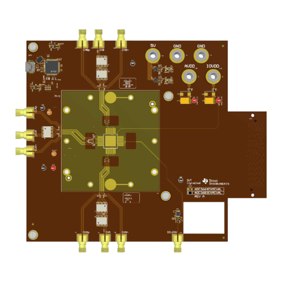
ADC36xxEVMCVAL (Top View)
SBAU446 – DECEMBER 2023
Submit Document Feedback
Features
•
Transformer coupled or single-ended clock inputs
•
Transformer coupled or single-ended analog inputs
•
FMC connector
•
Single 5 V power supply jack for easy power-up
•
REF35160QDBVR Precision Voltage Reference
for the ADC 1.6 V external reference
•
REFBUF test point provides a hardware option to
change the voltage reference
Copyright © 2023 Texas Instruments Incorporated
ADC36xxEVMCVAL (Bottom View)
ADC36xxEVMCVAL Evaluation Module
Description
1
Advertisement
Table of Contents

Subscribe to Our Youtube Channel
Related Manuals for Texas Instruments ADC36 EVMCVAL Series


Summary of Contents for Texas Instruments ADC36 EVMCVAL Series
- Page 1 • Transformer coupled or single-ended clock inputs used to evaluate the ADC36XXQML-SP analog-to- • Transformer coupled or single-ended analog inputs digital converter (ADC) from Texas Instruments. The • FMC connector ADC36XXQML-SP uses a serial LVDS interface • Single 5 V power supply jack for easy power-up to output the digital data.
-
Page 2: Kit Contents
The ADC36xxEVMCVAL LVDS output data is routed to an FMC connector, and then connected to an LVDS Interposer card. This interposer card then maps to the HSMC connector of the TSW1400EVM to capture the ADC36xxEVMCVAL SLVDS clock and data signals. ADC36xxEVMCVAL Evaluation Module SBAU446 – DECEMBER 2023 Submit Document Feedback Copyright © 2023 Texas Instruments Incorporated... -
Page 3: Device Information
Quad high speed USB to multipurpose UART/ FT4232HL FTDI chip MPSSE IC 93LC46B Serial EEPROM FTDI circuit UX60SC-MB-5S8 Mini-USB connector Surface mount Mini-USB connector SBAU446 – DECEMBER 2023 ADC36xxEVMCVAL Evaluation Module Submit Document Feedback Copyright © 2023 Texas Instruments Incorporated... -
Page 4: Software Installation
ADC35XX EVM GUI download can be found using the following link, under the Related Design Sources tab: ADC35XX EVM GUI. Once downloaded, extract and run the executable file and accept the default installation options. ADC36xxEVMCVAL Evaluation Module SBAU446 – DECEMBER 2023 Submit Document Feedback Copyright © 2023 Texas Instruments Incorporated... - Page 5 Hardware 3 Hardware 3.1 Additional Images Figure 3-1. ADC36xxEVMCVAL Features Identification (Top) Figure 3-2. ADC36xxEVMCVAL Features Identification (Bottom) SBAU446 – DECEMBER 2023 ADC36xxEVMCVAL Evaluation Module Submit Document Feedback Copyright © 2023 Texas Instruments Incorporated...
-
Page 6: Power Requirements
(AVDD and IOVDD) and 3.3 V (1A) via test clips for VREF. Also needed is 5 V (4A) via J12 power jack on the TSW1400EVM. ADC36xxEVMCVAL Evaluation Module SBAU446 – DECEMBER 2023 Submit Document Feedback Copyright © 2023 Texas Instruments Incorporated... -
Page 7: Test Points
(bottom side of the board) is +1.6 VDC +/- 0.1 V. This is the voltage to be supplied as the external reference to the part. See the images below for reference to this location. SBAU446 – DECEMBER 2023 ADC36xxEVMCVAL Evaluation Module Submit Document Feedback Copyright © 2023 Texas Instruments Incorporated... - Page 8 (frequency locked). This is usually accomplished by connecting the 10 MHz input and output ports on the back panel of the signal generators using BNC cables. ADC36xxEVMCVAL Evaluation Module SBAU446 – DECEMBER 2023 Submit Document Feedback Copyright © 2023 Texas Instruments Incorporated...
- Page 9 Simply click the slider to turn off if the CDC Clock Enable slider is still enabled. Perform a software reset by clicking Reset and then click the Configure button to configure the part. Figure 4-1. ADC35XXEVM GUI Configuration SBAU446 – DECEMBER 2023 ADC36xxEVMCVAL Evaluation Module Submit Document Feedback Copyright © 2023 Texas Instruments Incorporated...
- Page 10 The capture above is a typical result from the default configuration. Remember that typical values can vary slightly depending on the setup and the quality of SMA cables, signal generators and filters that are used in the setup. ADC36xxEVMCVAL Evaluation Module SBAU446 – DECEMBER 2023 Submit Document Feedback Copyright © 2023 Texas Instruments Incorporated...
-
Page 11: Additional Information
For the BOM, please refer to the Design files tab on the product page for ADC36xxEVMCVAL. 6 Additional Information 6.1 Trademarks All trademarks are the property of their respective owners. SBAU446 – DECEMBER 2023 ADC36xxEVMCVAL Evaluation Module Submit Document Feedback Copyright © 2023 Texas Instruments Incorporated... - Page 12 STANDARD TERMS FOR EVALUATION MODULES Delivery: TI delivers TI evaluation boards, kits, or modules, including any accompanying demonstration software, components, and/or documentation which may be provided together or separately (collectively, an “EVM” or “EVMs”) to the User (“User”) in accordance with the terms set forth herein.
- Page 13 www.ti.com Regulatory Notices: 3.1 United States 3.1.1 Notice applicable to EVMs not FCC-Approved: FCC NOTICE: This kit is designed to allow product developers to evaluate electronic components, circuitry, or software associated with the kit to determine whether to incorporate such items in a finished product and software developers to write software applications for use with the end product.
- Page 14 www.ti.com Concernant les EVMs avec antennes détachables Conformément à la réglementation d'Industrie Canada, le présent émetteur radio peut fonctionner avec une antenne d'un type et d'un gain maximal (ou inférieur) approuvé pour l'émetteur par Industrie Canada. Dans le but de réduire les risques de brouillage radioélectrique à...
- Page 15 www.ti.com EVM Use Restrictions and Warnings: 4.1 EVMS ARE NOT FOR USE IN FUNCTIONAL SAFETY AND/OR SAFETY CRITICAL EVALUATIONS, INCLUDING BUT NOT LIMITED TO EVALUATIONS OF LIFE SUPPORT APPLICATIONS. 4.2 User must read and apply the user guide and other available documentation provided by TI regarding the EVM prior to handling or using the EVM, including without limitation any warning or restriction notices.
- Page 16 Notwithstanding the foregoing, any judgment may be enforced in any United States or foreign court, and TI may seek injunctive relief in any United States or foreign court. Mailing Address: Texas Instruments, Post Office Box 655303, Dallas, Texas 75265 Copyright © 2023, Texas Instruments Incorporated...
-
Page 17: Important Notice
TI products. TI’s provision of these resources does not expand or otherwise alter TI’s applicable warranties or warranty disclaimers for TI products. TI objects to and rejects any additional or different terms you may have proposed. IMPORTANT NOTICE Mailing Address: Texas Instruments, Post Office Box 655303, Dallas, Texas 75265 Copyright © 2023, Texas Instruments Incorporated...
Need help?
Do you have a question about the ADC36 EVMCVAL Series and is the answer not in the manual?
Questions and answers