Advertisement
Quick Links
www.ti.com
EVM User's Guide: ADC3910D125EVM
ADC3910D125 Evaluation Module
Description
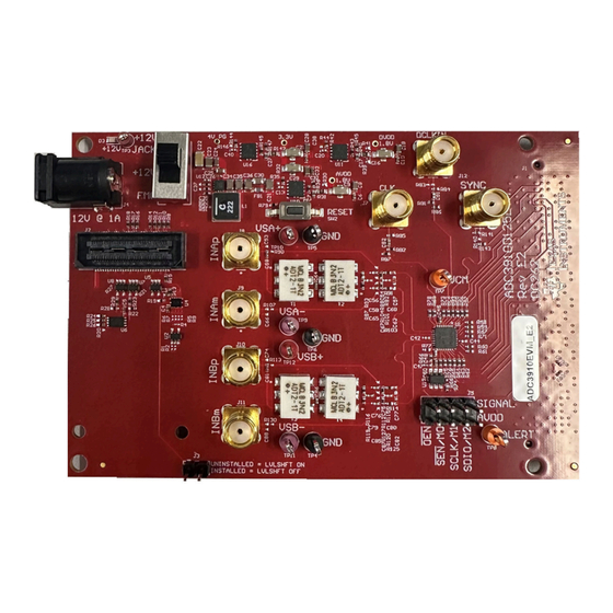
The ADC3910D125EVM is an evaluation module
(EVM) designed to evaluate the ADC3910D125 family
of high speed ADCs. The ADC3910D125EVM is
populated with a ADC3910D125, 10-bit ADC, dual-
channel, LVCMOS interface, and can operate up
to 125MSPS. The ADC3910D125EVM allows for
evaluation of all device speed grades, 25MSPS,
65MSPS, and 125MSPS.
Get Started
1. Order the EVM on ti.com.
2. Download the latest revision of the data sheet
(SBASAD1).
3. Download
High Speed Data Converter Pro
(HSDC
Pro).
SBAU442 – DECEMBER 2023
Submit Document Feedback
Features
•
10-bit, 125 MSPS ADC
•
Dual-channel
•
Ultra-low power
•
Latency: 1 clock cycle
•
Buffered inputs
•
Small footprint: 32-VQFN (4mm x 4mm)
Applications
•
Radio receiver
•
LiDAR
•
Low latency control loops
•
Laser scanners
•
GPS
•
SMU
•
Detection equipment
ADC3910D125EVM
Copyright © 2023 Texas Instruments Incorporated
Description
ADC3910D125 Evaluation Module
1
Advertisement

Related Manuals for Texas Instruments ADC3910D125EVM


Summary of Contents for Texas Instruments ADC3910D125EVM
- Page 1 The ADC3910D125EVM is an evaluation module • 10-bit, 125 MSPS ADC (EVM) designed to evaluate the ADC3910D125 family • Dual-channel of high speed ADCs. The ADC3910D125EVM is • Ultra-low power populated with a ADC3910D125, 10-bit ADC, dual- • Latency: 1 clock cycle channel, LVCMOS interface, and can operate up •...
- Page 2 1 Evaluation Module Overview 1.1 Introduction The ADC3910D125EVM allows for evaluation of all ADC39XX versions as the versions are all P2P compatible. By default, the ADC3910D125EVM, has the ADC3910D125 (10-bit, 125MSPS). The EVM is configured to receive external single-ended analog inputs as the EVM includes baluns for single-ended to differential conversion.
- Page 3 Make sure that SW1 is set to take power from the +12V jack, the included FTDI board is connected to J2, and jumpers J3 & J5 remain uninstalled. Figure 2-2. FTDI board Included with ADC3910D125EVM That Connects to J2 SBAU442 – DECEMBER 2023...
- Page 4 5. Connect a +12V power supply to the barrel connector (power supply cable included with EVM) of the ADC3910D125EVM. 6. Connect a mini USB cable from the PC to the FTDI board installed on the ADC3910D125EVM. 7. Connect a mini USB cable from the PC to J2 on the TSW1418EVM.
- Page 5 Microsoft ® 5. Download the ADC3910D125EVM_API_Rev0.1 supplemental software folder found in the ADC3910D125EVM product folder or provided by TI. 4 Implementation Results 4.1 Evaluation Setup Once the software setup and hardware setups are completed. Follow these steps to get a capture on the ADC3910D125EVM: 1.
- Page 6 In the hw_ila_1 waveform view, select all the values and right click. In the pop-up menu, hover over Radix and in the next pop-up menu, select Signed Decimal. Figure 4-4. Changing ILA radix to signed decimal ADC3910D125 Evaluation Module SBAU442 – DECEMBER 2023 Submit Document Feedback Copyright © 2023 Texas Instruments Incorporated...
- Page 7 In HSDC Pro, an FFT of the input signals needs to be captured. 4.2 EVM Capture Figure 4-6. FS = 125MSPS; Fin = 10.097503662M @ 8.2dBm SBAU442 – DECEMBER 2023 ADC3910D125 Evaluation Module Submit Document Feedback Copyright © 2023 Texas Instruments Incorporated...
- Page 8 The schematics are available on the product page of ADC3910D125EVM. 5.2 PCB Layouts The board layout is available on the product page of ADC3910D125EVM. 5.3 Bill of Materials (BOM) The bill of materials is available on the product page of ADC3910D125EVM. 6 Additional Information 6.1 Trademarks Vivado ™...
- Page 9 STANDARD TERMS FOR EVALUATION MODULES Delivery: TI delivers TI evaluation boards, kits, or modules, including any accompanying demonstration software, components, and/or documentation which may be provided together or separately (collectively, an “EVM” or “EVMs”) to the User (“User”) in accordance with the terms set forth herein.
- Page 10 www.ti.com Regulatory Notices: 3.1 United States 3.1.1 Notice applicable to EVMs not FCC-Approved: FCC NOTICE: This kit is designed to allow product developers to evaluate electronic components, circuitry, or software associated with the kit to determine whether to incorporate such items in a finished product and software developers to write software applications for use with the end product.
- Page 11 www.ti.com Concernant les EVMs avec antennes détachables Conformément à la réglementation d'Industrie Canada, le présent émetteur radio peut fonctionner avec une antenne d'un type et d'un gain maximal (ou inférieur) approuvé pour l'émetteur par Industrie Canada. Dans le but de réduire les risques de brouillage radioélectrique à...
- Page 12 www.ti.com EVM Use Restrictions and Warnings: 4.1 EVMS ARE NOT FOR USE IN FUNCTIONAL SAFETY AND/OR SAFETY CRITICAL EVALUATIONS, INCLUDING BUT NOT LIMITED TO EVALUATIONS OF LIFE SUPPORT APPLICATIONS. 4.2 User must read and apply the user guide and other available documentation provided by TI regarding the EVM prior to handling or using the EVM, including without limitation any warning or restriction notices.
- Page 13 Notwithstanding the foregoing, any judgment may be enforced in any United States or foreign court, and TI may seek injunctive relief in any United States or foreign court. Mailing Address: Texas Instruments, Post Office Box 655303, Dallas, Texas 75265 Copyright © 2023, Texas Instruments Incorporated...
- Page 14 TI products. TI’s provision of these resources does not expand or otherwise alter TI’s applicable warranties or warranty disclaimers for TI products. TI objects to and rejects any additional or different terms you may have proposed. IMPORTANT NOTICE Mailing Address: Texas Instruments, Post Office Box 655303, Dallas, Texas 75265 Copyright © 2023, Texas Instruments Incorporated...
Need help?
Do you have a question about the ADC3910D125EVM and is the answer not in the manual?
Questions and answers