Table of Contents
Advertisement
Quick Links
www.ti.com
User's Guide
ADC366xEVM Evaluation Module
Abstract
This user's guide describes the characteristics, operation, and use of the ADC366x evaluation module (EVM).
This user's guide discusses how to set up and configure the software and hardware, and reviews various
aspects of the program operation. Throughout this document, the terms evaluation board, evaluation module,
and EVM are synonymous with the ADC366xEVM. In the following sections of this document, the ADC366x
evaluation board is referred to as the EVM and the ADC366x devices are referred to as the ADC devices,
respectively. This document applies only to the ADC3663EVM and ADC3662EVM.
Abstract......................................................................................................................................................................................
1
Introduction.............................................................................................................................................................................2
2 Equipment...............................................................................................................................................................................
Functionality...............................................................................................................................................2
2.3 Required Equipment..........................................................................................................................................................
3 Setup Procedure.....................................................................................................................................................................
3.1 Install High-Speed Data Converter (HSDC) Pro Software.................................................................................................
3.2 Install ADC35XXEVM GUI 1.0 Software............................................................................................................................
3.4 Connect the Power Supply and Mini-USB Connections....................................................................................................
4 ADC GUI Configuration..........................................................................................................................................................
4.1 Bypass Mode.....................................................................................................................................................................
Mode.....................................................................................................................................................13
4.3 Complex Decimation Mode..............................................................................................................................................
5 Onboard Clocking Hardware Setup....................................................................................................................................
5.2 Onboard Clock: ADC35XX GUI Real Decimation Mode .................................................................................................
Configuration................................................................................................................................................................23
7 ADC36xxEVM Power Monitor..............................................................................................................................................
8 Test Pattern...........................................................................................................................................................................
SBAU366 - JANUARY 2021
Submit Document Feedback
Table of Contents
Summary.............................................................................................................4
TSW1400EVM................................................................................................................6
Input................................................................................................................................7
Modfications......................................................................................................................20
Copyright © 2021 Texas Instruments Incorporated
Abstract
ADC366xEVM Evaluation Module
1
2
5
6
6
6
7
8
9
16
19
22
25
26
1
Advertisement
Table of Contents

Related Manuals for Texas Instruments ADC366 EVM Series


Summary of Contents for Texas Instruments ADC366 EVM Series
-
Page 1: Table Of Contents
5.1 Onboard Clocking: Hardware Modfications........................20 5.2 Onboard Clock: ADC35XX GUI Real Decimation Mode ....................6 FDA Configuration................................23 7 ADC36xxEVM Power Monitor.............................. 8 Test Pattern................................... SBAU366 – JANUARY 2021 ADC366xEVM Evaluation Module Submit Document Feedback Copyright © 2021 Texas Instruments Incorporated... -
Page 2: Introduction
The ADC366xEVM is an evaluation board used to evaluate the ADC366x analog-to-digital converters (ADC) from Texas Instruments. The ADC366x uses a serial LVDS interface to output the digital data. The serialized LVDS interface supports output rates to 1 Gbps. The ADC366x can be operated in 'oversampling + decimating' mode using the internal decimation filter in order to improve the dynamic range and relax external anti-aliasing filter. - Page 3 Equipment Figure 2-1. ADC36xxEVM block diagram: Balun input Figure 2-2. ADC36xxEVM block diagram: FDA input SBAU366 – JANUARY 2021 ADC366xEVM Evaluation Module Submit Document Feedback Copyright © 2021 Texas Instruments Incorporated...
-
Page 4: Evaluation Board Feature Identification Summary
J14 is tied to the PDN/SYNC pin. It can be left floating for tied to ground (shunt pins 1-2) for normal operation. To power down the ADC, tied to 1.8 V (shunt pins 2-3). The ADC may also be powered down via SPI. ADC366xEVM Evaluation Module SBAU366 – JANUARY 2021 Submit Document Feedback Copyright © 2021 Texas Instruments Incorporated... -
Page 5: Required Equipment
Bandpass filter, greater than or equal to 60-dB harmonic attenuation, less than or equal to 5% bandwidth, greater than 18-dBm power, less than 5-dB insertion loss • Signal-path cables, SMA SBAU366 – JANUARY 2021 ADC366xEVM Evaluation Module Submit Document Feedback Copyright © 2021 Texas Instruments Incorporated... -
Page 6: Setup Procedure
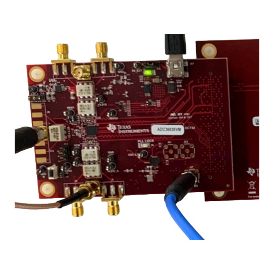
Connect the ADC366xEVM FMC connector to J4 of the LVDS Interposer Card. Connect J5 of the LVDS Interposer Card to J1 of the TSW1400EVM. Figure 3-1. ADC366xEVM Complete Setup (external clocks) ADC366xEVM Evaluation Module SBAU366 – JANUARY 2021 Submit Document Feedback Copyright © 2021 Texas Instruments Incorporated... -
Page 7: Connect The Power Supply And Mini-Usb Connections
For the analog input, set a signal generator to 5 MHz at a power level of ~ +15 dBm. A bandpass filter is required to reduce harmonic and phase noise effects of the signal generator. SBAU366 – JANUARY 2021 ADC366xEVM Evaluation Module Submit Document Feedback Copyright © 2021 Texas Instruments Incorporated... -
Page 8: Adc Gui Configuration
Also, a software reset may be performed at any time to reset the ADC registers to their default state. Figure 4-1. ADC35xx Software Reset ADC366xEVM Evaluation Module SBAU366 – JANUARY 2021 Submit Document Feedback Copyright © 2021 Texas Instruments Incorporated... -
Page 9: Bypass Mode
Ensure that "CDC Enable" is red (disabled). • To calculate the DCLKIN frequency, enter "65" in the Fs(MHz) field, and click calculate. This is informational only. • Click "Configure" button. SBAU366 – JANUARY 2021 ADC366xEVM Evaluation Module Submit Document Feedback Copyright © 2021 Texas Instruments Incorporated... - Page 10 ADC GUI Configuration www.ti.com Figure 4-2. ADC35XXEVM GUI: ADC3663 Bypass Mode ADC366xEVM Evaluation Module SBAU366 – JANUARY 2021 Submit Document Feedback Copyright © 2021 Texas Instruments Incorporated...
- Page 11 Enter the input frequency of the input signal in the box that says "ADC Input Target Frequency" (5 MHz used in this example). • Click "Capture" . SBAU366 – JANUARY 2021 ADC366xEVM Evaluation Module Submit Document Feedback Copyright © 2021 Texas Instruments Incorporated...
- Page 12 ADC GUI Configuration www.ti.com • The analog input signal power may need to be adjusted to reach -1 dBFS. ADC366xEVM Evaluation Module SBAU366 – JANUARY 2021 Submit Document Feedback Copyright © 2021 Texas Instruments Incorporated...
-
Page 13: Real Decimation Mode
To calculate the DCLKIN frequency, enter "65" in the Fs(MHz) field, and click calculate. This is informational only. • Ensure that "CDC Enable" is red (disabled). • Click "Configure" SBAU366 – JANUARY 2021 ADC366xEVM Evaluation Module Submit Document Feedback Copyright © 2021 Texas Instruments Incorporated... - Page 14 In the new dialogue box, enter "65M" in "ADC Sampling Rate" • Enter "1M" in "ADC Input Frequency" • Enter "16" in "Decimation" • Click "OK" • Click "Capture" ADC366xEVM Evaluation Module SBAU366 – JANUARY 2021 Submit Document Feedback Copyright © 2021 Texas Instruments Incorporated...
- Page 15 ADC GUI Configuration Figure 4-5. HSDC Pro Cog Wheel (Real Decimation) Figure 4-6. HSDC Pro 16x Real Decimation FFT (2W, 16 bit) SBAU366 – JANUARY 2021 ADC366xEVM Evaluation Module Submit Document Feedback Copyright © 2021 Texas Instruments Incorporated...
-
Page 16: Complex Decimation Mode
Under "FNCO A (MHz)" and "FNCO B (MHz)", enter "9.9" in the field. This field then calculates to the nearest valid NCO value, and auto-calculates the correct register values in the field next to it. • Click "Configure". ADC366xEVM Evaluation Module SBAU366 – JANUARY 2021 Submit Document Feedback Copyright © 2021 Texas Instruments Incorporated... - Page 17 Under “ADC Input Frequency”, enter "10M" • Under "NCO", enter "9.9M" • Under “Decimation”, enter "32". • Click "OK". Figure 4-8. HSDC Pro Cog Parameters: 32x Complex Decimation Mode SBAU366 – JANUARY 2021 ADC366xEVM Evaluation Module Submit Document Feedback Copyright © 2021 Texas Instruments Incorporated...
- Page 18 ADC GUI Configuration www.ti.com • Select "Complex FFT" • Press "Capture" Figure 4-9. HSDC Pro 32x Complex Decimation (2W, 16 bit) ADC366xEVM Evaluation Module SBAU366 – JANUARY 2021 Submit Document Feedback Copyright © 2021 Texas Instruments Incorporated...
-
Page 19: Onboard Clocking Hardware Setup
10 MSPS) in Bypass and Decimation modes. The ADC35XX GUI does not support configuring the CDCE6214 to frequencies outside of these preset selections at this time. SBAU366 – JANUARY 2021 ADC366xEVM Evaluation Module Submit Document Feedback Copyright © 2021 Texas Instruments Incorporated... -
Page 20: Onboard Clocking: Hardware Modfications
Install R41, R51 (0-Ω resistor) Figure 5-2. ADC36xxEVM Onboard Sample clock modifications Onboard DCLKIN Modification: • Install R60 and R62 (0-Ω resistor) • DNI R35 and R36 ADC366xEVM Evaluation Module SBAU366 – JANUARY 2021 Submit Document Feedback Copyright © 2021 Texas Instruments Incorporated... - Page 21 Onboard Clocking Hardware Setup Figure 5-3. ADC36xxEVM Onboard DCLKIN modifications SBAU366 – JANUARY 2021 ADC366xEVM Evaluation Module Submit Document Feedback Copyright © 2021 Texas Instruments Incorporated...
-
Page 22: Onboard Clock: Adc35Xx Gui Real Decimation Mode
"CDC Clock Enable" button must be enabled (Green), and the "Configure CDC" button must be clicked. The PLL_LOCK LED (D1) also illuminates to ensure CDCE6214 has been configured correctly. Figure 5-4. AD35xx EVM GUI: Onboard Clock 16x Real Decimation ADC366xEVM Evaluation Module SBAU366 – JANUARY 2021 Submit Document Feedback Copyright © 2021 Texas Instruments Incorporated... -
Page 23: Fda Configuration
AC coupling to FDA. Modify the following components to complete path to FDA (located on top of EVM). • Install: R1, R2, R14 (o ohm) SBAU366 – JANUARY 2021 ADC366xEVM Evaluation Module Submit Document Feedback Copyright © 2021 Texas Instruments Incorporated... - Page 24 The termination resistors (R80, R81, R89 and R90) can be adjusted according to the source impedance. Figure 6-3. FDA schematic For further information on the THS4541 FDA, please refer to the THS4541 datasheet. ADC366xEVM Evaluation Module SBAU366 – JANUARY 2021 Submit Document Feedback Copyright © 2021 Texas Instruments Incorporated...
-
Page 25: Adc36Xxevm Power Monitor
This feature is useful for determining what mode/sampling speed offers the best power consumption for your application needs. Figure 7-1. ADC36xxEVM Power Meter SBAU366 – JANUARY 2021 ADC366xEVM Evaluation Module Submit Document Feedback Copyright © 2021 Texas Instruments Incorporated... -
Page 26: Test Pattern
(Bypass, Real Decimation and Complex Decimation). Trademarks Microsoft ® and Windows ® are registered trademarks of Microsoft Corporation. All trademarks are the property of their respective owners. ADC366xEVM Evaluation Module SBAU366 – JANUARY 2021 Submit Document Feedback Copyright © 2021 Texas Instruments Incorporated... - Page 27 STANDARD TERMS FOR EVALUATION MODULES Delivery: TI delivers TI evaluation boards, kits, or modules, including any accompanying demonstration software, components, and/or documentation which may be provided together or separately (collectively, an “EVM” or “EVMs”) to the User (“User”) in accordance with the terms set forth herein.
- Page 28 www.ti.com Regulatory Notices: 3.1 United States 3.1.1 Notice applicable to EVMs not FCC-Approved: FCC NOTICE: This kit is designed to allow product developers to evaluate electronic components, circuitry, or software associated with the kit to determine whether to incorporate such items in a finished product and software developers to write software applications for use with the end product.
- Page 29 www.ti.com Concernant les EVMs avec antennes détachables Conformément à la réglementation d'Industrie Canada, le présent émetteur radio peut fonctionner avec une antenne d'un type et d'un gain maximal (ou inférieur) approuvé pour l'émetteur par Industrie Canada. Dans le but de réduire les risques de brouillage radioélectrique à...
- Page 30 www.ti.com EVM Use Restrictions and Warnings: 4.1 EVMS ARE NOT FOR USE IN FUNCTIONAL SAFETY AND/OR SAFETY CRITICAL EVALUATIONS, INCLUDING BUT NOT LIMITED TO EVALUATIONS OF LIFE SUPPORT APPLICATIONS. 4.2 User must read and apply the user guide and other available documentation provided by TI regarding the EVM prior to handling or using the EVM, including without limitation any warning or restriction notices.
- Page 31 Notwithstanding the foregoing, any judgment may be enforced in any United States or foreign court, and TI may seek injunctive relief in any United States or foreign court. Mailing Address: Texas Instruments, Post Office Box 655303, Dallas, Texas 75265 Copyright © 2019, Texas Instruments Incorporated...
- Page 32 TI products. TI’s provision of these resources does not expand or otherwise alter TI’s applicable warranties or warranty disclaimers for TI products.IMPORTANT NOTICE Mailing Address: Texas Instruments, Post Office Box 655303, Dallas, Texas 75265 Copyright © 2021, Texas Instruments Incorporated...
Need help?
Do you have a question about the ADC366 EVM Series and is the answer not in the manual?
Questions and answers