Table of Contents
Advertisement
Quick Links
www.ti.com
User's Guide
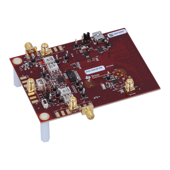
ADC364xEVM Evaluation Module
Abstract
This user's guide describes the characteristics, operation, and use of the ADC364x evaluation module (EVM).
This user's guide discusses how to set up and configure the software and hardware, and reviews various
aspects of the program operation. Throughout this document, the terms evaluation board, evaluation module,
and EVM are synonymous with the ADC364xEVM. In the following sections of this document, the ADC364x
evaluation board is referred to as the EVM and the ADC364x device is referred to as the ADC device.
Abstract......................................................................................................................................................................................
1
Introduction.............................................................................................................................................................................2
2 Equipment...............................................................................................................................................................................
2.2 Required Equipment..........................................................................................................................................................
3 Setup Procedure.....................................................................................................................................................................
3.1 Install High-Speed Data Converter (HSDC) Pro Software.................................................................................................
3.2 Install ADC35XXEVM GUI 1.0 Software............................................................................................................................
3.4 Connect the Power Supply and Mini-USB Connections....................................................................................................
Configuration..............................................................................................................................................................7
4.1 Bypass Mode.....................................................................................................................................................................
Mode.....................................................................................................................................................12
4.3 Complex Decimation Mode..............................................................................................................................................
5 External Clocking Hardware Setup.....................................................................................................................................
5.1 Hardware Modfications....................................................................................................................................................
5.2 Hardware Setup: Real Decimation 16x Mode..................................................................................................................
6 ADC364xEVM Power Monitor..............................................................................................................................................
7 Test Pattern...........................................................................................................................................................................
SBAU232 - OCTOBER 2020
Submit Document Feedback
Table of Contents
Summary.............................................................................................................3
TSW1400EVM.......................................................................................................................5
..................................................................................................24
Copyright © 2020 Texas Instruments Incorporated
Abstract
ADC364xEVM Evaluation Module
1
3
4
5
5
5
6
8
16
20
20
24
25
26
1
Advertisement
Table of Contents

Related Manuals for Texas Instruments ADC364 EVM Series


Summary of Contents for Texas Instruments ADC364 EVM Series
-
Page 1: Table Of Contents
5.1 Hardware Modfications..............................5.2 Hardware Setup: Real Decimation 16x Mode........................5.3 External Clock: ADC35XX GUI Real Decimation Mode ....................24 6 ADC364xEVM Power Monitor.............................. 7 Test Pattern................................... SBAU232 – OCTOBER 2020 ADC364xEVM Evaluation Module Submit Document Feedback Copyright © 2020 Texas Instruments Incorporated... -
Page 2: Introduction
The ADC364xEVM is an evaluation board used to evaluate the ADC364x analog-to-digital converter (ADC) from Texas Instruments. The ADC364xEVM is a dual-channel, 14-bit ADC that can operate up to 125 Mega-samples per second (MSPS). The ADC364x uses a parallel or serial CMOS interface to output the digital data. The serialized CMOS interface supports output rates to 250 Mbps which translates to ~ 30 MSPS (2-wire) to ~ 10 MSPS (0.5-wire) output rates after complex decimation. -
Page 3: Equipment
Ensure that jumper J8 is shunted in the 2-3 position. This allows 5 V to be supplied to the ADC364xEVM through the mini-USB connector. SBAU232 – OCTOBER 2020 ADC364xEVM Evaluation Module Submit Document Feedback Copyright © 2020 Texas Instruments Incorporated... -
Page 4: Required Equipment
Bandpass filter, greater than or equal to 60-dB harmonic attenuation, less than or equal to 5% bandwidth, greater than 18-dBm power, less than 5-dB insertion loss • Signal-path cables, SMA ADC364xEVM Evaluation Module SBAU232 – OCTOBER 2020 Submit Document Feedback Copyright © 2020 Texas Instruments Incorporated... -
Page 5: Setup Procedure
Connect the ADC364xEVM FMC connector to J1 of the FPGA Interposer Card. Connect J2 of the FPGA Interposer Card to J1 of the TSW1400EVM. Figure 3-1. ADC3660EVM Full Setup SBAU232 – OCTOBER 2020 ADC364xEVM Evaluation Module Submit Document Feedback Copyright © 2020 Texas Instruments Incorporated... -
Page 6: Connect The Power Supply And Mini-Usb Connections
2. Connect the power cable to the TSW1400EVM at 5-V (minimum 3 A) power supply. Place the power switch (SW7) to the "On" position. 3. Connect the mini-USB cable to the TSW1400EVM (J2). 4. Connect the mini-USB cable to the ADC3643EVM (J14). ADC364xEVM Evaluation Module SBAU232 – OCTOBER 2020 Submit Document Feedback Copyright © 2020 Texas Instruments Incorporated... -
Page 7: Device Configuration
A software reset may be performed at any time to reset the ADC registers to their default state. Figure 4-1. ADC35xx Software Reset Replace this image SBAU232 – OCTOBER 2020 ADC364xEVM Evaluation Module Submit Document Feedback Copyright © 2020 Texas Instruments Incorporated... -
Page 8: Bypass Mode
Ensure that "CDC Enable" is green (enabled). • Click "Configure CDC" button. • Click "Configure" button. Figure 4-2. ADC35xx GUI settings for Bypass Mode ADC364xEVM Evaluation Module SBAU232 – OCTOBER 2020 Submit Document Feedback Copyright © 2020 Texas Instruments Incorporated... - Page 9 Launch HSDC Pro • Select the TSW1400 and click OK Figure 4-3. HSDC Pro: Connect to TSW1400 • Click OK for the no firmware loaded prompt. SBAU232 – OCTOBER 2020 ADC364xEVM Evaluation Module Submit Document Feedback Copyright © 2020 Texas Instruments Incorporated...
- Page 10 • Enter the input frequency of the input signal in the box that says "ADC Input Target Frequency" (5 MHz used in this example). ADC364xEVM Evaluation Module SBAU232 – OCTOBER 2020 Submit Document Feedback Copyright © 2020 Texas Instruments Incorporated...
- Page 11 Device Configuration • Press Capture Figure 4-5. Bypass Mode Capture • The analog input signal power may need to be adjusted to reach -1 dBFS. SBAU232 – OCTOBER 2020 ADC364xEVM Evaluation Module Submit Document Feedback Copyright © 2020 Texas Instruments Incorporated...
-
Page 12: Real Decimation Mode
For Decimation Factor, select 16. • For Fs(MHz), select 60M. • Click Configure CDC • Click Configure Figure 4-6. ADC35xx GUI settings for Real Decimation Mode ADC364xEVM Evaluation Module SBAU232 – OCTOBER 2020 Submit Document Feedback Copyright © 2020 Texas Instruments Incorporated... - Page 13 Click OK for the no firmware loaded prompt. • Select “ADC3643_2W_14bit_CMOS” to load firmware, and click Yes. Figure 4-7. Real Decimation HSDC Pro INI File • SBAU232 – OCTOBER 2020 ADC364xEVM Evaluation Module Submit Document Feedback Copyright © 2020 Texas Instruments Incorporated...
- Page 14 Device Configuration www.ti.com Click on the cog next to “ADC Output Data Rate”. Figure 4-8. Real Decimation Mode HSDC Pro Parameters • ADC364xEVM Evaluation Module SBAU232 – OCTOBER 2020 Submit Document Feedback Copyright © 2020 Texas Instruments Incorporated...
- Page 15 Enter 1M in “ADC Input Frequency” • Enter 16 in “Decimation”. • Click Ok. • Click the Capture button Figure 4-9. HSDC Pro Cog Wheel SBAU232 – OCTOBER 2020 ADC364xEVM Evaluation Module Submit Document Feedback Copyright © 2020 Texas Instruments Incorporated...
-
Page 16: Complex Decimation Mode
• Click Configure CDC Figure 4-10. ADC35xx GUI settings for Complex Decimation Mode ADC364xEVM Evaluation Module SBAU232 – OCTOBER 2020 Submit Document Feedback Copyright © 2020 Texas Instruments Incorporated... - Page 17 Click OK for the "no firmware loaded" prompt. • Select “ADC3643_2W_14bit_CMOS_Complex” to load firmware, and click Yes. Figure 4-11. Complex Decimation HSDC Pro INI file • SBAU232 – OCTOBER 2020 ADC364xEVM Evaluation Module Submit Document Feedback Copyright © 2020 Texas Instruments Incorporated...
- Page 18 Under "NCO", enter "9.9M" • Under “Decimation”, enter "16". • Click "OK". Figure 4-12. Complex Decimation Mode HSDC Pro Parameters • Select "Complex FFT" ADC364xEVM Evaluation Module SBAU232 – OCTOBER 2020 Submit Document Feedback Copyright © 2020 Texas Instruments Incorporated...
- Page 19 Device Configuration • Press "Capture" Figure 4-13. Complex Mode Capture SBAU232 – OCTOBER 2020 ADC364xEVM Evaluation Module Submit Document Feedback Copyright © 2020 Texas Instruments Incorporated...
-
Page 20: External Clocking Hardware Setup
The following hardware modifications must be made in order to operate the ADC364xEVM using an external sample and (if required) data clock . External Sample Clock Modification: ADC364xEVM Evaluation Module SBAU232 – OCTOBER 2020 Submit Document Feedback Copyright © 2020 Texas Instruments Incorporated... - Page 21 Install R36, R37 (0-Ω resistor) • Connect sample clock to J8. Connect DCLKIN to J15. Figure 5-1. ADC364xEVM Schematic Snippet: Sample Clock External DCLKIN Modification: • DNI R176 SBAU232 – OCTOBER 2020 ADC364xEVM Evaluation Module Submit Document Feedback Copyright © 2020 Texas Instruments Incorporated...
- Page 22 External Clocking Hardware Setup www.ti.com • Replace C129 with 0-Ω resistor. Figure 5-2. ADC364xEVM Schematic Snippet: DCKLIN ADC364xEVM Evaluation Module SBAU232 – OCTOBER 2020 Submit Document Feedback Copyright © 2020 Texas Instruments Incorporated...
- Page 23 External Clocking Hardware Setup • SBAU232 – OCTOBER 2020 ADC364xEVM Evaluation Module Submit Document Feedback Copyright © 2020 Texas Instruments Incorporated...
-
Page 24: Hardware Setup: Real Decimation 16X Mode
Decimation Configuration". The only difference that must be observed in the GUI is "CDC Clock Enable" button must be disabled (red) before selecting "Configure" in the ADC35xx GUI. Figure 5-3. ADC35XX GUI: Disable CDC Clock Enable ADC364xEVM Evaluation Module SBAU232 – OCTOBER 2020 Submit Document Feedback Copyright © 2020 Texas Instruments Incorporated... -
Page 25: Adc364Xevm Power Monitor
This feature is useful for determining what mode/sampling speed offers the best power consumption for your application needs. Figure 6-1. ADC364xEVM Power Meter SBAU232 – OCTOBER 2020 ADC364xEVM Evaluation Module Submit Document Feedback Copyright © 2020 Texas Instruments Incorporated... -
Page 26: Test Pattern
The digital ramp pattern is now enabled on the ADC. The output of the ADC is now a 14 bit, incrementing ramp pattern. Figure 7-1. ADC35XXEVM GUI 1.0 Ramp Pattern ADC364xEVM Evaluation Module SBAU232 – OCTOBER 2020 Submit Document Feedback Copyright © 2020 Texas Instruments Incorporated... - Page 27 Figure 7-2. HSDC Pro Digital Ramp Pattern Trademarks Microsoft ® and Windows ® are registered trademarks of Microsoft Corporation. All other trademarks are the property of their respective owners. SBAU232 – OCTOBER 2020 ADC364xEVM Evaluation Module Submit Document Feedback Copyright © 2020 Texas Instruments Incorporated...
- Page 28 STANDARD TERMS FOR EVALUATION MODULES Delivery: TI delivers TI evaluation boards, kits, or modules, including any accompanying demonstration software, components, and/or documentation which may be provided together or separately (collectively, an “EVM” or “EVMs”) to the User (“User”) in accordance with the terms set forth herein.
- Page 29 www.ti.com Regulatory Notices: 3.1 United States 3.1.1 Notice applicable to EVMs not FCC-Approved: FCC NOTICE: This kit is designed to allow product developers to evaluate electronic components, circuitry, or software associated with the kit to determine whether to incorporate such items in a finished product and software developers to write software applications for use with the end product.
- Page 30 www.ti.com Concernant les EVMs avec antennes détachables Conformément à la réglementation d'Industrie Canada, le présent émetteur radio peut fonctionner avec une antenne d'un type et d'un gain maximal (ou inférieur) approuvé pour l'émetteur par Industrie Canada. Dans le but de réduire les risques de brouillage radioélectrique à...
- Page 31 www.ti.com EVM Use Restrictions and Warnings: 4.1 EVMS ARE NOT FOR USE IN FUNCTIONAL SAFETY AND/OR SAFETY CRITICAL EVALUATIONS, INCLUDING BUT NOT LIMITED TO EVALUATIONS OF LIFE SUPPORT APPLICATIONS. 4.2 User must read and apply the user guide and other available documentation provided by TI regarding the EVM prior to handling or using the EVM, including without limitation any warning or restriction notices.
- Page 32 Notwithstanding the foregoing, any judgment may be enforced in any United States or foreign court, and TI may seek injunctive relief in any United States or foreign court. Mailing Address: Texas Instruments, Post Office Box 655303, Dallas, Texas 75265 Copyright © 2019, Texas Instruments Incorporated...
- Page 33 TI products. TI’s provision of these resources does not expand or otherwise alter TI’s applicable warranties or warranty disclaimers for TI products. Mailing Address: Texas Instruments, Post Office Box 655303, Dallas, Texas 75265 Copyright © 2020, Texas Instruments Incorporated...
Need help?
Do you have a question about the ADC364 EVM Series and is the answer not in the manual?
Questions and answers