
Subscribe to Our Youtube Channel
Related Manuals for Texas Instruments ADC12J4000EVM


Summary of Contents for Texas Instruments ADC12J4000EVM
- Page 1 ADC12J4000EVM User's Guide User's Guide Literature Number: SLAU551B January 2014 – Revised August 2015...
-
Page 2: Table Of Contents
Connect the Signal Generators to the EVM (*RF outputs disabled until directed) ............Turn On the TSW14J56EVM Power and Connect to the PC ........... Turn On the ADC12J4000EVM Power Supplies and Connect to the PC ................Turn On the Signal Generator RF Outputs .......... - Page 3 List of Tables ..........4-1. Supported and Non-Supported Features of the JESD204B Device ......................4-2. Low-Level Controls ......................5-1. Troubleshooting SLAU551B – January 2014 – Revised August 2015 List of Figures Submit Documentation Feedback Copyright © 2014–2015, Texas Instruments Incorporated...
-
Page 4: Introduction
SLAU551B – January 2014 – Revised August 2015 Introduction The ADC12J4000EVM is an evaluation board used to evaluate the ADC12J4000 analog-to-digital converter (ADC) from Texas Instruments. The ADC12J4000 device is a single-channel, 12-bit ADC capable of operating at sampling rates up to 4 Giga-samples per second (GSPS). The ADC12J4000 device output data is transmitted over a standard JESD204B high-speed serial interface. - Page 5 With proper hardware selection in the HSDC Pro software, the TSW14J56 device is automatically configured to support a wide range of operating speeds of the ADC12J4000EVM, but the device may not cover the full operating range of the ADC device. Serial data rates (and corresponding sampling rates) of 10 Gb/s (4 GSPS) down to 1 Gb/s (1 GSPS) are supported.
- Page 6 Introduction SLAU551B – January 2014 – Revised August 2015 Submit Documentation Feedback Copyright © 2014–2015, Texas Instruments Incorporated...
-
Page 7: Equipment
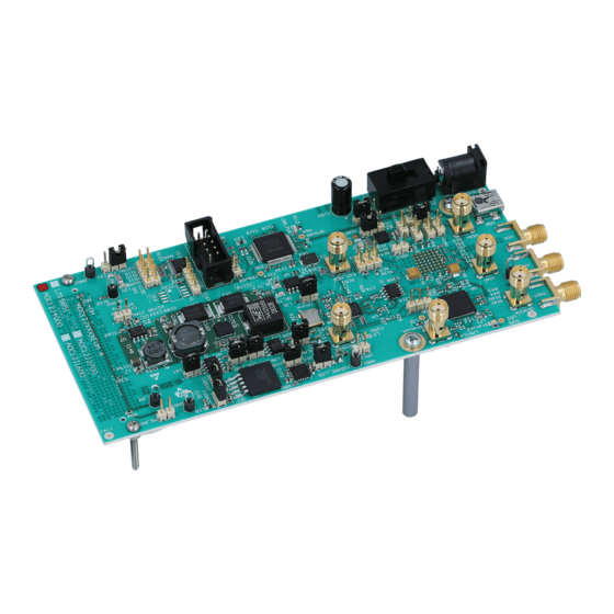
This section describes how to setup the EVM on the bench with the proper equipment to evaluate the full performance of the ADC device. Evaluation Board Feature Identification Summary Figure 2-1. EVM Feature Locations SLAU551B – January 2014 – Revised August 2015 Equipment Submit Documentation Feedback Copyright © 2014–2015, Texas Instruments Incorporated... -
Page 8: Required Equipment
– TTE KC6 or KC7-series fixed BPF • Signal-path cables, SMA or BNC (or both SMA and BNC) By default, the ADC12J4000EVM has an onboard clocking solution. A few small board modifications enable external clocking. If external clocking is used, the following equipment is recommended. •... - Page 9 Required Equipment www.ti.com SLAU551B – January 2014 – Revised August 2015 Equipment Submit Documentation Feedback Copyright © 2014–2015, Texas Instruments Incorporated...
-
Page 10: Setup Procedure
Figure 3-1. EVM Test Setup NOTE: The HSDC Pro software must be installed before connecting the TSW14J56EVM to the PC for the first time. Setup Procedure SLAU551B – January 2014 – Revised August 2015 Submit Documentation Feedback Copyright © 2014–2015, Texas Instruments Incorporated... -
Page 11: Install The High Speed Data Converter (Hsdc) Pro Software
1. Confirm that the power switch on the TSW14J56EVM is in the off position. Connect the 5-V power supply adapter to the TSW14J56EVM. 2. Confirm that the 5-V power supply for the ADC12J4000EVM is turned off. Connect the 5-V power supply to the power connector (the power connector that is the closest to the USB connector). -
Page 12: Turn On The Adc12J4000Evm Power Supplies And Connect To The Pc
Turn On the ADC12J4000EVM Power Supplies and Connect to the PC www.ti.com 2. Connect a mini-USB cable from the PC to the TSW14J56EVM. 3. If this is the first time connecting the TSW14J56EVM to the PC, then follow the on-screen instructions to automatically install the device drivers. -
Page 13: Configure Nco Tab (If Decimation Is Selected)
2. Select Preset 0 for NCO Preset Select 3. Change Preset 0 Frequency to 583951944, which corresponds to an NCO frequency of 543.847627938 MHz. SLAU551B – January 2014 – Revised August 2015 Setup Procedure Submit Documentation Feedback Copyright © 2014–2015, Texas Instruments Incorporated... -
Page 14: Calibrate The Adc Device On The Evm
4. To stop Background Calibration Mode, first click the "Start/Stop Background CAL" button, then click the "Enable Background CAL" button. Then click the Execute Foreground CAL button once to properly calibration the device in Foreground Mode. Setup Procedure SLAU551B – January 2014 – Revised August 2015 Submit Documentation Feedback Copyright © 2014–2015, Texas Instruments Incorporated... -
Page 15: Open The Hsdc Software And Load The Fpga Image To The Tsw14J56Evm
NOTE: There are 3 new device files labeled ADC12J4000A_D10_DDR, ADC12J4000A_D20_DDR.ini and ADC12J4000A_D20_SDR.ini. These should be used with the new ADC12J4000EVM Rev A. The original files without the A suffix are still available for compatibility with the earlier revision EVM. If the user configures the EVM with options other than the default register values, different instructions may be required for selecting the device in HSDC Pro. -
Page 16: High Speed Data Converter Pro (Hsdc) Gui
The HSDC Pro GUI will calculate the ADC Output Data Rate based on these inputs. The Fundamental and Harmonic frequency locations will also be calculated and identified in the FFT display. Setup Procedure SLAU551B – January 2014 – Revised August 2015 Submit Documentation Feedback Copyright © 2014–2015, Texas Instruments Incorporated... -
Page 17: Re-Verify Tsw14J56Evm Status Leds
Verify the status of the D1 to D8 LEDs on the TSW14J56EVM. See the TSW14J56EVM user guide (SLWU086) for more information regarding the status LEDs. SLAU551B – January 2014 – Revised August 2015 Setup Procedure Submit Documentation Feedback Copyright © 2014–2015, Texas Instruments Incorporated... - Page 18 Re-Verify TSW14J56EVM Status LEDs www.ti.com Setup Procedure SLAU551B – January 2014 – Revised August 2015 Submit Documentation Feedback Copyright © 2014–2015, Texas Instruments Incorporated...
-
Page 19: Device Configuration
Write register button Write to the register highlighted in the register map summary with the value in the Write Data field SLAU551B – January 2014 – Revised August 2015 Device Configuration Submit Documentation Feedback Copyright © 2014–2015, Texas Instruments Incorporated... -
Page 20: Low-Level Register Control Tab
Individual register cluster with Perform a generic read or write command to the device shown in the Block drop-down box using read or write register buttons the address and write data information Figure 4-1. Low-Level Register Control Tab Device Configuration SLAU551B – January 2014 – Revised August 2015 Submit Documentation Feedback Copyright © 2014–2015, Texas Instruments Incorporated... - Page 21 Low-Level Control www.ti.com SLAU551B – January 2014 – Revised August 2015 Device Configuration Submit Documentation Feedback Copyright © 2014–2015, Texas Instruments Incorporated...
-
Page 22: Evaluation Troubleshooting
• Verify that bandpass filters are used in the clock and input signal paths and that low-noise signal sources are used. Evaluation Troubleshooting SLAU551B – January 2014 – Revised August 2015 Submit Documentation Feedback Copyright © 2014–2015, Texas Instruments Incorporated... - Page 23 SLAU551B – January 2014 – Revised August 2015 Evaluation Troubleshooting Submit Documentation Feedback Copyright © 2014–2015, Texas Instruments Incorporated...
-
Page 24: References
FTDI USB to Serial Driver Installation Manual, www.ftdichip.com/Support/Documents/InstallGuides.htm TSW14J56EVM Operation Refer to the TSW14J56EVM user guide SLWU086 for configuration and status information. References SLAU551B – January 2014 – Revised August 2015 Submit Documentation Feedback Copyright © 2014–2015, Texas Instruments Incorporated... - Page 25 TSW14J56EVM Operation www.ti.com SLAU551B – January 2014 – Revised August 2015 References Submit Documentation Feedback Copyright © 2014–2015, Texas Instruments Incorporated...
-
Page 26: Bhsdc Pro Settings For Optional Adc Device Configuration
(a) In the EVM tab, set the Clock Source to External. (b) Enter the Sampling Frequency (F ) in step 2(b). DEVCLK HSDC Pro Settings for Optional ADC Device Configuration SLAU551B – January 2014 – Revised August 2015 Submit Documentation Feedback Copyright © 2014–2015, Texas Instruments Incorporated... - Page 27 For a full evaluation platform see the LMK04828 tool folder: www.ti.com/tool/lmk04828bevm and the TRF3765 tool folder: http://www.ti.com/tool/trf3765evm. SLAU551B – January 2014 – Revised August 2015 HSDC Pro Settings for Optional ADC Device Configuration Submit Documentation Feedback Copyright © 2014–2015, Texas Instruments Incorporated...
- Page 28 Customizing the EVM for Optional Clocking Support www.ti.com HSDC Pro Settings for Optional ADC Device Configuration SLAU551B – January 2014 – Revised August 2015 Submit Documentation Feedback Copyright © 2014–2015, Texas Instruments Incorporated...
-
Page 29: Revision History
Changed Configuration for Optional Clocking Support image. NOTE: Page numbers for previous revisions may differ from page numbers in the current version. SLAU551B – January 2014 – Revised August 2015 Revision History Submit Documentation Feedback Copyright © 2014–2015, Texas Instruments Incorporated... - Page 30 STANDARD TERMS AND CONDITIONS FOR EVALUATION MODULES Delivery: TI delivers TI evaluation boards, kits, or modules, including any accompanying demonstration software, components, or documentation (collectively, an “EVM” or “EVMs”) to the User (“User”) in accordance with the terms and conditions set forth herein. Acceptance of the EVM is expressly subject to the following terms and conditions.
- Page 31 FCC Interference Statement for Class B EVM devices NOTE: This equipment has been tested and found to comply with the limits for a Class B digital device, pursuant to part 15 of the FCC Rules. These limits are designed to provide reasonable protection against harmful interference in a residential installation.
- Page 32 【無線電波を送信する製品の開発キットをお使いになる際の注意事項】 開発キットの中には技術基準適合証明を受けて いないものがあります。 技術適合証明を受けていないもののご使用に際しては、電波法遵守のため、以下のいずれかの 措置を取っていただく必要がありますのでご注意ください。 1. 電波法施行規則第6条第1項第1号に基づく平成18年3月28日総務省告示第173号で定められた電波暗室等の試験設備でご使用 いただく。 2. 実験局の免許を取得後ご使用いただく。 3. 技術基準適合証明を取得後ご使用いただく。 なお、本製品は、上記の「ご使用にあたっての注意」を譲渡先、移転先に通知しない限り、譲渡、移転できないものとします。 上記を遵守頂けない場合は、電波法の罰則が適用される可能性があることをご留意ください。 日本テキサス・イ ンスツルメンツ株式会社 東京都新宿区西新宿6丁目24番1号 西新宿三井ビル 3.3.3 Notice for EVMs for Power Line Communication: Please see http://www.tij.co.jp/lsds/ti_ja/general/eStore/notice_02.page 電力線搬送波通信についての開発キットをお使いになる際の注意事項については、次のところをご覧くださ い。http://www.tij.co.jp/lsds/ti_ja/general/eStore/notice_02.page SPACER EVM Use Restrictions and Warnings: 4.1 EVMS ARE NOT FOR USE IN FUNCTIONAL SAFETY AND/OR SAFETY CRITICAL EVALUATIONS, INCLUDING BUT NOT LIMITED TO EVALUATIONS OF LIFE SUPPORT APPLICATIONS.
- Page 33 Notwithstanding the foregoing, any judgment may be enforced in any United States or foreign court, and TI may seek injunctive relief in any United States or foreign court. Mailing Address: Texas Instruments, Post Office Box 655303, Dallas, Texas 75265 Copyright © 2015, Texas Instruments Incorporated...
- Page 34 IMPORTANT NOTICE Texas Instruments Incorporated and its subsidiaries (TI) reserve the right to make corrections, enhancements, improvements and other changes to its semiconductor products and services per JESD46, latest issue, and to discontinue any product or service per JESD48, latest issue.
- Page 35 Mouser Electronics Authorized Distributor Click to View Pricing, Inventory, Delivery & Lifecycle Information: Texas Instruments ADC12J4000EVM...
Need help?
Do you have a question about the ADC12J4000EVM and is the answer not in the manual?
Questions and answers