Paradyne 7974 User Manual
M/sdsl standalone termination units
Hide thumbs
Also See for 7974:
- User manual (166 pages) ,
- Installation instructions manual (41 pages) ,
- Wall mounting installation instructions (4 pages)

Related Manuals for Paradyne 7974


Summary of Contents for Paradyne 7974
- Page 1 HOTWIRE M/SDSL STANDALONE TERMINATION UNITS MODELS 7974-A2, 7975-A2, AND 7976-A2 USER’S GUIDE Document No. 7900-A2-GB21-00 August 2000...
- Page 2 Copyright E 2000 Paradyne Corporation. All rights reserved. Printed in U.S.A. Notice This publication is protected by federal copyright law. No part of this publication may be copied or distributed, transmitted, transcribed, stored in a retrieval system, or translated into any human or computer language in any form or by any means, electronic, mechanical, magnetic, manual or otherwise, or disclosed to third parties without the express written permission of Paradyne Corporation, 8545 126th Ave.
-
Page 3: Table Of Contents
Contents About This Guide H Document Purpose and Intended Audience H Document Summary H Product-Related Documents About the Hotwire Standalone Termination Unit H M/SDSL Overview H Hotwire Standalone Termination Unit Features H Network Configuration H Front Panel LED Status Indicators H Rear Panel Interface Connections H SNMP Management Capabilities Management Information Base (MIB) Support... - Page 4 Configuring the Unit Using the Internal Switches H Overview H Configuring the Unit Using the Internal Switches Switchpack Locations Switchpack Definitions for Model 7974 Switchpack Definitions for Model 7975 Switchpack Definitions for Model 7976 IP Addressing H Selecting an IP Addressing Scheme...
- Page 5 H Entry Response Messages H Viewing Network Error Statistics H Viewing Network Performance Statistics H Viewing DSX-1 Performance Statistics (Model 7974) H Viewing G.703 Performance Statistics (Model 7976) H Using the Display LEDs Screen H Hotwire Standalone Termination Unit LEDs...
- Page 6 Telco-Initiated Remote Line Loopback Configuration Options H Overview H Network Interface Options Menu H DSX-1 Interface Options for Model 7974 H Synchronous Data Port Options for Model 7975 H G.703 Interface Options for Model 7976 H System Options Menu H Communication Port...
- Page 7 Standards Compliance for SNMP Traps H SNMP Traps H ifIndex Variable Binding H warmStart H authenticationFailure H linkUp and linkDown H Enterprise-Specific Traps Cables and Pin Assignments H Overview H Power Input Connector H COM Port Connector H COM Port-to-PC Cable H COM Port-to-LAN Adapter Cable H DSX-1/G.703 Network Interface H EIA-530-A Port...
- Page 8 Contents This page intentionally left blank. August 2000 7900-A2-GB21-00...
-
Page 9: About This Guide
Document Purpose and Intended Audience This guide contains information needed to set up, configure, and operate the Hotwire Multirate Symmetric Digital Subscriber Line (M/SDSL) Standalone Termination Unit, Models 7974-A2, 7975-A2 and 7976-A2, and is intended for installers and operators. Document Summary... -
Page 10: H Product-Related Documents
Lists key terms, acronyms, concepts, and sections in alphabetical order. Document Title Hotwire M/SDSL Standalone Termination Units, Models 7974-A2, 7975-A2, and 7976-A2, Installation Instructions Hotwire M/SDSL and HDSL2 Termination Units, Models 8747, 8777, and 8779, User’s Guide Hotwire M/SDSL and M/HDSL Termination Units, Models 8775 and 8785, User’s Guide... -
Page 11: About The Hotwire Standalone Termination Unit
About the Hotwire Standalone Termination Unit M/SDSL Overview Hotwirer Multirate Symmetric Digital Subscriber Line (M/SDSL) products maximize customer service areas by varying the DSL line rate. This ensures symmetric DSL connectivity over a wide range of telephone line distances and transmission line qualities. -
Page 12: H Hotwire Standalone Termination Unit Features
About the Hotwire Standalone Termination Unit Hotwire Standalone Termination Unit Features The Hotwire Standalone Termination Unit is an endpoint for the chassis-mounted Hotwire 877x Termination Unit housed in the Hotwire 8600 Series or 8800 Series Digital Subscriber Line Access Multiplexer (DSLAM). Two Hotwire Standalone Termination Units can also be configured to operate in a central office line termination unit (LTU) to customer premises network termination unit (NTU) environment. -
Page 13: Network Configuration
Network Configuration Figure 1-1 shows a network application using a termination unit in a central office (CO). In this configuration, a frame relay switch and a router are connected through the termination unit to partner units supporting a host or router, and frame relay encapsulated or unframed data. -
Page 14: Front Panel Led Status Indicators
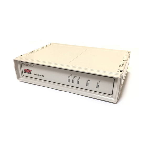
Monitoring and Figure 1-2. Hotwire DSX-1 Interface Termination Unit Front Panel Figure 1-3. Hotwire Synchronous Interface Termination Unit Front Panel Figure 1-4. Hotwire G.703 Interface Termination Unit Front Panel Troubleshooting. 7974 M/SDSL 7975 M/SDSL 7976 M/SDSL August 2000 98-16116 98-15856... -
Page 15: Rear Panel Interface Connections
Rear Panel Interface Connections Figures 1-5 through 1-7 show the physical interfaces of the termination units. Figure 1-5. Hotwire DSX-1 Interface Termination Unit Rear Panel Figure 1-6. Hotwire Synchronous Interface Termination Unit Rear Panel Figure 1-7. Hotwire G.703 Interface Termination Unit Rear Panel 7900-A2-GB21-00 About the Hotwire Standalone Termination Unit POWER... -
Page 16: H Snmp Management Capabilities
TCP/IP internets and provides general information about the unit. MIB II is backward-compatible with MIB I. DS1/E1 MIB (RFC 1406) – Models 7974 and 7976. Reports the performance status of the DSX-1 or G.703 interface and supports the features found on the DSX-1 or G.703 Performance Statistics screen. -
Page 17: Snmp Trap Support
SNMP Trap Support Hotwire 797x Standalone Termination Units support traps as defined in RFC 1215. Figure 1-8 illustrates a typical DSL SNMP configuration. Figure 1-9 illustrates an DSL SNMP configuration connected directly to the Communications Port. Refer to Chapter 5, Traps. - Page 18 About the Hotwire Standalone Termination Unit This page intentionally left blank. August 2000 7900-A2-GB21-00...
-
Page 19: Using The Asynchronous Terminal Interface
Using the Asynchronous Terminal Interface User Interface Access You can communicate with the Hotwire Standalone Termination Unit with an asynchronous terminal interface (ATI) using one of the following methods: Direct connection through the COM port of the standalone unit or through the serial port of the DSLAM management card. -
Page 20: Initiating An Ati Session
Using the Asynchronous Terminal Interface Initiating an ATI Session The Main Menu screen is displayed on the screen unless a login ID and password is required or the ATI is already in use. If the ATI is already in use, you will see: A connection refused or connection failed message (if you are using a Telnet session), or The IP address of the other user (if you are using the Management Serial... - Page 21 After you enter a valid login ID and password, the Main Menu appears. If you enter an invalid login ID and password after three attempts, the Telnet session closes or the terminal connection returns to an idle state. Refer to Chapter 6, Security.
-
Page 22: Menu Tree
7975: (Not Applicable) Statistics 7976: G.703 Statistics Network Performance Statistics 7974: (Not Applicable) 7975: Sync Data Port Tests 7976: (Not Applicable) 7974: Network and DSX-1 Tests 7975: Network Tests 7976: Network and G.703 Tests Network Main Test Configuration Display Identity... -
Page 23: Screen Work Areas
Screen Work Areas There are two user work areas: Screen area – This is the area above the dotted line that provides the menu path, menus, and input fields. The menu path appears as the first line on the screen. In this manual, the menu path is presented as a menu selection sequence with the names of the screens: Main Menu... -
Page 24: H Navigating The Screens
Using the Asynchronous Terminal Interface Navigating the Screens You can navigate the screens by: Using keyboard keys Using screen function keys Switching between the two screen work areas Keyboard Keys Use the following keyboard keys to navigate within the screen. Press . -
Page 25: Screen Function Keys
" Procedure To make a menu or field selection: 1. Press the Tab key or the right arrow key to position the cursor on a menu or field selection. Each selection is highlighted as you press the key to move the cursor from position to position. -
Page 26: Switching Between Screen Work Areas
Using the Asynchronous Terminal Interface Switching Between Screen Work Areas Select Ctrl-a to switch between the two screen work areas to perform all screen functions. " Procedure To access the screen function area below the dotted line: 1. Press Ctrl-a to switch from the screen area to the screen function key area below the dotted line. -
Page 27: Initial Startup And Configuration
Initial Startup and Configuration Overview This chapter provides instructions on how to access and configure your Hotwire 797x Standalone Termination Unit for the first time. This chapter includes procedures for: Connecting power to the unit. Connecting the unit to the network. Connecting the unit to a DTE. -
Page 28: H Connecting Power
Initial Startup and Configuration Connecting Power If your package includes a power pack: Plug the power pack into an AC outlet having a nominal voltage rating between 100–240 VAC. Connect the output cable of the power pack to the connector marked POWER on the rear panel. If your package includes a direct-connection DC power cable: Connect the unit to an external +24 or –48 VDC power source as described in Connecting the Unit to an Optional External DC Power Source. -
Page 29: Connecting To The Network
Connecting to a DTE As the following table shows, the DTE interface varies from model to model. Model DTE Connection 7974 The DSX-1 interface is an RJ48C, 8-position, unkeyed modular connector. An RJ48C-to-DB15 T1 network interface adapter cable is available from Paradyne. -
Page 30: Connecting To A System Terminal
Initial Startup and Configuration Connecting to a System Terminal An optional system maintenance terminal may be attached to your Hotwire 797x Standalone Termination Unit through the modular jack on the rear panel. The system maintenance terminal allows you to view the status of the unit and change configuration options. -
Page 31: Entering Identity Information
Entering Identity Information After accessing your unit for the first time, use the Change Identity screen to determine SNMP administrative system information that will be displayed on the Identity screen of the Status branch. To access the Identity screen, follow this menu selection sequence: Main Menu main/control/change_identity... - Page 32 Initial Startup and Configuration " Procedure To enter Change Identity screen information: 1. Position the cursor in the System Name field. Enter a name unique in your network to identify the SNMP managed node (or unit). The maximum length of System Name is 128 characters. 2.
-
Page 33: H Choosing A Configuration Method
Choosing a Configuration Method You can make configuration changes either through a VT100-compatible terminal and the unit’s Configuration menus or by manually changing switches on the board. The unit is shipped with the switchpacks disabled to allow settings to be made through the Configuration menus. -
Page 34: Accessing And Displaying Configuration Options
Initial Startup and Configuration Accessing and Displaying Configuration Options To display configuration options, you must first load a configuration into the edit area. To load a configuration option set into the configuration edit area, follow this menu selection sequence: Main Menu main/configuration Î... -
Page 35: H Configuration Edit/Display
Configuration Edit/Display The Configuration Edit/Display screen appears when the current or default configuration is loaded. To access the Configuration Edit/Display screen, follow this menu selection sequence: Main Menu – or – Main Menu main/config/edit Î ––––––––––––––––––––––––––––––––––––––––––––––––––––––––––––––––––––––––––––––– Î Ctrl-a to access these functions, ESC for previous menu Save 7900-A2-GB21-00 Initial Startup and Configuration... -
Page 36: H Snmp Traps
SNMP Traps Options, Table A-13 August 2000 To Configure the . . . DSL network interface on the unit. DSX-1 interface (Model 7974) Synchronous DTE interface (Model 7975) G.703 interface (Model 7976) General system options of the unit. Unit’s COM port options. -
Page 37: Configuration Loader
Configuration Loader The Configuration Loader screen allows you to upload configurations to and download configurations from a TFTP server. To access the Configuration Loader screen, follow this menu selection sequence: Main Menu Î Î Î Î Î Î Î Î Î Î Î Î Î Î Î Î Î Î Î Î Î Î Î Î Î main/configuration/config_loader Î... - Page 38 Initial Startup and Configuration " Procedure To upload or download a configuration: 1. Position the cursor in the Image File Name field. Type the name of the file to be downloaded, or the name to be used for the file to be uploaded. The filename may be a regular path name expression of directory names separated by a forward slash (/ ) ending with the filename.
-
Page 39: Saving Configuration Options
Saving Configuration Options When changes are made to the configuration options through the Configuration Edit/Display branch, the changes must be saved to take effect. Use the Save key or Save Configuration screen. " Procedure To save configuration options changes: 1. Press Ctrl-a to switch to the screen function key area below the dotted line. 2. -
Page 40: H Downloading Code
Initial Startup and Configuration Downloading Code The Download Code screen allows you to download firmware from a TFTP server. To access the Download Code screen, follow this menu selection sequence: Main Menu Î Î Î Î Î Î Î Î Î Î Î Î Î Î Î Î Î Î Î Î Î Î Î Î Î Î... - Page 41 " Procedure To download firmware: 1. Position the cursor in the Image File Name field. Type the name of the file to be downloaded. The file name may be a regular path name expression of directory names separated by a forward slash (/ ) ending with the file name. The total path name length can be up to 128 characters.
-
Page 42: H Disabling Autorate
Initial Startup and Configuration Disabling AutoRate The M/SDSL AutoRate function is controlled from the Network Interface Options screen and allows you to enable or disable AutoRate. The AutoRate option is only available if the unit is configured as an LTU. To access the Network Interface screen, follow this menu selection sequence: Main Menu main/config/network... -
Page 43: Configuring The Unit Using The Internal Switches
Configuring the Unit Using the Internal Switches Overview You can make configuration changes either through a VT100-compatible terminal and the unit’s Configuration menus or by manually changing switches on the board. The unit is shipped with the switchpacks disabled to allow settings to be made through the Configuration menus. -
Page 44: H Configuring The Unit Using The Internal Switches
Configuring the Unit Using the Internal Switches Configuring the Unit Using the Internal Switches Use internal Switchpacks S3 and S4 to manually configure the unit. Use Figure 4-1 HANDLING PRECAUTIONS FOR STATIC-SENSITIVE DEVICES This product is designed to protect sensitive components from damage due to electrostatic discharge (ESD) during normal operation. -
Page 45: Switchpack Locations
Switchpack Locations Use Figure 4-1 to locate Switchpacks S3 and S4. Switchpack S3 & S4 1 2 3 4 5 1 2 3 4 5 Figure 4-1. Hotwire Standalone Termination Unit Switchpack Locations 7900-A2-GB21-00 Configuring the Unit Using the Internal Switches Rear 6 7 8 1 2 3 4 5... -
Page 46: Switchpack Definitions For Model 7974
Switch # . . . 6, 7, 8 Use Table 4-2 to set the Line Equalization. Defaults are shown in bold. Table 4-2. Line Equalization, Switches 6–8 on Switchpack S4 (Model 7974) Switch Position Allows you to . . . - Page 47 Switch # . . . 3, 4, 5 Use Table 4-4 to set the DSL Line Rate. Defaults are shown in bold. Table 4-4. DSL Line Rate, Switches 3–5 on Switchpack S3 (Model 7974) Switch Position 7900-A2-GB21-00 Configuring the Unit Using the Internal Switches Allows you to .
-
Page 48: Switchpack Definitions For Model 7975
Configuring the Unit Using the Internal Switches Switchpack Definitions for Model 7975 Table 4-5 lists Switchpack S4 definitions. Table 4-5. Switchpack S4 Definitions (Model 7975) Switch # . . . 4, 5, 6, 7, 8 Use Table 4-6 to set the Sync Port Payload Rate. Defaults are shown in bold. NOTE: Sync Port and DSL Line Rates can only be selected from a unit configured as the LTU (Switchpack S3 #1) with AutoRate disabled (Switchpack S3 #2). - Page 49 Table 4-6. Selectable Payload Rates (Model 7975) Sync Port Payload Rate 2048 kbps (32 x 64) 1984 kbps (31 x 64) 1920 kbps (30 x 64) 1856 kbps (29 x 64) 1792 kbps (28 x 64) 1728 kbps (27 x 64) 1664 kbps (26 x 64) 1600 kbps (25 x 64) 1536 kbps (24 x 64)
- Page 50 Configuring the Unit Using the Internal Switches Table 4-7 lists Switchpack S3 definitions. Table 4-7. Switchpack S3 Definitions (Model 7975) Switch # . . . 3, 4, 5 Use Table 4-8 to set the DSL Line Rate. Defaults are shown in bold. Table 4-8.
-
Page 51: Switchpack Definitions For Model 7976
Switchpack Definitions for Model 7976 Table 4-9 lists Switchpack S4 definitions. Table 4-9. Switchpack S4 Definitions (Model 7976) Switch # . . . 7900-A2-GB21-00 Configuring the Unit Using the Internal Switches Allows you to . . . Enable or disable Switchpacks S3 and S4. OFF = Switchpacks Disabled ON = Switchpacks Enabled Control line termination. - Page 52 Configuring the Unit Using the Internal Switches Table 4-10 lists Switchpack S3 definitions. Table 4-10. Switchpack S3 Definitions (Model 7976) Switch # . . . 3, 4, 5 6, 7 Use Table 4-11 to set the DSL Line Rate. Defaults are shown in bold. Table 4-11.
-
Page 53: Ip Addressing
IP Addressing Selecting an IP Addressing Scheme Your IP addressing scheme depends in part whether the Hotwire 797x Standalone Termination Unit is running in IP Conservative mode. The unit runs in IP Conservative mode if it is connected to a DSLAM card running in IP Conservative mode. - Page 54 IP Addressing The Peer IP Address refers to the EOC interface IP address of the unit configured as an NTU. When the LTU and NTU negotiate a connection, the NTU receives its address from the LTU. Review the following information in preparation for selecting an IP addressing scheme.
-
Page 55: H Overview
Security Overview Security on the Hotwire 797x Standalone Termination Unit is implemented by limiting user access to the ATI through option settings. You can: Enable the Telnet Login Required option. Enable the COM port Login Required option. Limit access by setting a Session Access Level option of Operator for the Telnet session. -
Page 56: Ati Access Levels
Security ATI Access Levels The Hotwire 797x Standalone Termination Unit has two access levels: Administrator and Operator. The access level determines what functions are accessible, as shown in Table 6-1. Table 6-1. Access Levels ATI Access to Menu Functions Status Test Configuration Control... -
Page 57: Creating A Login
Creating a Login Logins apply to the terminal directory connected to the communication port or Telnet access directly to the ATI of the unit. Six login ID/password combinations are available. Each Login ID and Password must be unique and include an access level. "... - Page 58 Security 3. Create the login by entering the following fields. Login IDs and passwords are case-sensitive. On the Login Entry screen, for the . . . Login ID Password Re-enter Password Access Level NOTE: Assign at least one Administrator-level Login ID. Full access is necessary to make configuration option changes and administer logins.
-
Page 59: Deleting A Login
Deleting a Login " Procedure 1. To delete a login record, follow this menu selection sequence: Main Menu 2. Select PgUp or PgDn and press Enter to page through login pages / records until you find the one to be deleted. 3. -
Page 60: H Resetting The Unit's Com Port Or Factory Defaults
Security Resetting the Unit’s COM Port or Factory Defaults The user interface can be rendered inaccessible with a faulty configuration. Two methods can be used to restore it: Reset COM Port – Allows you to reset the configuration options related to COM port usage. -
Page 61: H Controlling Snmp Access
Controlling SNMP Access There are three methods for limiting SNMP access: Disable the SNMP management option. Refer to Table A-11, Management Assign SNMP community names and access types. Limit SNMP access through validation of the IP address of each allowed SNMP manager. - Page 62 Security This page intentionally left blank. August 2000 7900-A2-GB21-00...
-
Page 63: Monitoring And Troubleshooting
Monitoring and Troubleshooting What to Monitor This chapter presents information on how to access and monitor Hotwire Standalone Termination Units. You can monitor a unit’s operations by viewing the: System and Test Status Highest priority Entry response messages Network Error Statistics Network Performance Statistics DSX-1 Display LEDs screen... -
Page 64: Viewing System And Test Status
Monitoring and Troubleshooting Viewing System and Test Status To view System and Test Status information, follow this menu selection sequence: Main Menu main/status/system HEALTH AND STATUS ––––––––––––––––––––––––––––––––––––––––––––––––––––––––––––––––––––––––––––––– System Operational Î ––––––––––––––––––––––––––––––––––––––––––––––––––––––––––––––––––––––––––––––– PgUp The System and Test Status screen has three sections: Health and Status –... -
Page 65: Health And Status Messages
Health and Status Messages The following messages can appear in the first column of the System and Test Status screen. The highest priority Health and Status message also appears on all ATI screens on the bottom right. Table 7-1. Health and Status Messages (1 of 2) Message AIS at DSX-1 AIS at G.703... - Page 66 Monitoring and Troubleshooting Table 7-1. Health and Status Messages (2 of 2) Message Mismatch Rate Net Com Link Down Net Margin Threshold NTU/LTU Mismatch NTU TS16 Not Supported OOF at Net Primary Clock Failed A failure has occurred in RAI (Remote Alarm Indication) at G.703 interface, Pt 1 SYNC Pt Down...
-
Page 67: Self-Test Results Messages
Self-Test Results Messages The results of the last power-up or reset self-test appear in the middle column of the System and Test Status screen. Table 7-2. Self-Test Results Messages Message CPU Failed DataPath Failed Device Failed DSX-1 Failed Sync Port Failed G.703 Failed Failure xxxxxxxx FPGA Download... -
Page 68: Test Status Messages
Monitoring and Troubleshooting Test Status Messages The Test Status messages in the following table appear in the right column of the System and Test Status screen. Table 7-3. Test Status Messages Test Status Message 511 Test Active DCLB Test Active DLB Test Active DTLB Test Active Lamp Test Active... - Page 69 Entry Response Messages The messages in Table 7-4, listed in alphabetical order, can appear in the messages area at the bottom of ATI screens in response to commands or data entry. Table 7-4. Entry Response Messages (1 of 2) Device Message 0.0.0.0 is an invalid IP address Access level is...
- Page 70 Monitoring and Troubleshooting Table 7-4. Entry Response Messages (2 of 2) Device Message Invalid Test Combination Limit of six Login IDs reached No Security Records to Delete Password Matching Error – Re-enter Password Please Wait Test Active What Message Indicates What To Do A loopback or pattern test Wait until other test ends.
-
Page 71: Viewing Network Error Statistics
Viewing Network Error Statistics The Hotwire 797x Standalone Termination Unit maintains error statistics on the network DSL interface. Statistics are maintained for up to 96 15-minute intervals (24 hours). To view the Network Error Statistics, follow this menu selection sequence: Main Menu Î... - Page 72 Monitoring and Troubleshooting Network Error Statistics are collected for: ES (Errored Seconds): Seconds during which one or more CRC error events occurred. SES (Severely Errored Seconds): Seconds during which more than 320 cyclic redundancy check (CRC) error events or at least one Out of Frame (OOF) event occurred.
-
Page 73: Viewing Network Performance Statistics
Viewing Network Performance Statistics Network performance statistics allow you to monitor the current status of the network DSL operations. Performance statistics can assist you in determining the duration of specific conditions and provide a historical context for problem detection and analysis. Statistics are maintained for up to 96 15-minute intervals (24 hours). - Page 74 Monitoring and Troubleshooting Network Performance Statistics are collected for: Mrgn: Signal to Noise Ratio (SNR) Margin is the difference of the SNR, measured every 10 seconds, and a set SNR reference value. The acceptable range for SNR Margin is 0 and above. However, it may be practical to tolerate values below 0 on bad lines or longer reaches.
-
Page 75: (Model 7974)
Viewing DSX-1 Performance Statistics (Model 7974) DSX-1 performance statistics allow you to monitor the current status of the DSX-1 interface operations when ESF framing is selected. Performance statistics can assist you in determining the duration of specific conditions and provide a historical context for problem detection and analysis. - Page 76 Monitoring and Troubleshooting DSX-1 Performance Statistics are collected for: ES (Errored Seconds): Seconds during which one or more error events occurred. UAS (Unavailable Seconds): Seconds during which service is unavailable. UAS is received at the start of 10 consecutive SES and cleared at the start of 10 seconds with no SES.
-
Page 77: (Model 7976)
Viewing G.703 Performance Statistics (Model 7976) G.703 performance statistics allow you to monitor the current status of the G.703 interface operations. Performance statistics can assist you in determining the duration of specific conditions and provide a historical context for problem detection and analysis. - Page 78 Monitoring and Troubleshooting G.703 Performance Statistics are collected for: ES (Errored Seconds): Seconds during which one or more error events occurred. UAS (Unavailable Seconds): Seconds during which service is unavailable. UAS is received at the start of 10 consecutive SES and cleared at the start of 10 seconds with no SES.
- Page 79 Using the Display LEDs Screen The Hotwire 797x Standalone Termination Unit LEDs can be viewed on the Display LEDs status screen. This ATI status screen is available locally and remotely. There are three classes of LEDs: General LEDs display the status of the unit The DTE (DSX-1, Sync Port, or G.703) LED provides the status of the DTE interface The DSL Loop LED displays the activity on the DSL network...
- Page 80 Monitoring and Troubleshooting Hotwire Standalone Termination Unit LEDs The Table 7-5 contains a description of the LEDs on the Hotwire 797x Standalone Termination Unit front panel. Table 7-5. Front Panel LEDs Label POWER ALARM TEST DSX-1 G.703 Slow Cycling: Fast Cycling: Pulsing: 7-18 7975 M/SDSL...
-
Page 81: Troubleshooting
Troubleshooting The Hotwire 797x Standalone Termination Unit is designed to provide you with many years of trouble-free service. If a problem occurs, however, refer to Table 7-6 for possible solutions. Table 7-6. Troubleshooting (1 of 2) Symptom ALARM LED is on. Cannot access the unit via the ATI. - Page 82 Monitoring and Troubleshooting Table 7-6. Troubleshooting (2 of 2) Symptom Not receiving data. Power-On Self-Test fails. Only POWER and ALARM LEDs are on after power-on. 7-20 Possible Cause Solutions The network or data port Check network and data port cables are not cables.
-
Page 83: Testing
7900-A2-GB21-00 Test TEST Network & DSX-1 Tests Network Tests Network & G.703 Tests SYNC Data Port Tests Device Tests Abort All Tests August 2000 Model: 797x (Model 7974) (Model 7975) (Model 7976) (Model 7975) Î Î Î Î MainMenu Exit... - Page 84 SYNC Data Port Tests Device Tests Abort All Tests On . . . To . . . Model 7974 Start and stop tests on the DSX-1 or network interface. Model 7975 Start and stop tests on the network interface. Model 7976 Start and stop tests on the G.703 or...
-
Page 85: Running Network Tests
Running Network Tests Network tests require the participation of your network service provider. To access the Network Tests screen, follow this menu selection sequence: Model 7974 (sample screen in Main Menu Model 7975 (sample screen below): Main Menu Model 7976 (sample screen in Main Menu Î... -
Page 86: Network Line Loopback
Testing Network Line Loopback Network Line Loopback loops the received signal on the network interface back to the network without change. Port Transceiver " Procedure To run a Network Line Loopback: 1. Position the cursor at the Start command next to Network Line Loopback on the Network &... -
Page 87: Remote Network Send Line Loopback
Remote Network Send Line Loopback The local unit initiates this test by sending a line loopback Up or Down command to the remote unit for 10 seconds. When the remote unit detects the loopback Up command, it puts itself in line loopback and lights the front panel test LED. The remote unit remains in loopback until it receives a loopback Down command or the remote unit’s test timeout value is exceeded. - Page 88 Testing DSX-1 Tests (Model 7974) To access the Network & DSX-1 Tests screen, follow this menu selection sequence: Main Menu Î Î Î Î Î Î Î Î Î Î Î Î Î Î Î Î Î Î Î Î Î Î Î Î Î...
-
Page 89: Network Repeater Loopback (Dsx-1)
Network Repeater Loopback (DSX-1) Network Repeater Loopback loops the signal being sent from the data port back to the data port and to the network interface. Activating the Network Repeater Loopback test causes the Embedded Operations Channel (EOC), used for management, to be lost to the remote unit. Port Transceiver "... -
Page 90: Dsx-1 Dte Loopback
Testing DSX-1 DTE Loopback DSX-1 DTE Loopback loops the DSX-1 signal back to itself before the signal is sent to the Framer. All Ones Port " Procedure To run a DSX-1 DTE Loopback: 1. Position the cursor at the Start command next to DSX-1 DTE Loopback on the Network &... -
Page 91: H Sync Data Port Tests (Model 7975)
SYNC Data Port Tests (Model 7975) To access the SYNC Data Port Tests screen, follow this menu selection sequence: Main Menu Î Î Î Î Î Î Î Î Î Î Î Î Î Î Î Î Î Î Î Î Î Î Î Î Î main/test/data Î... -
Page 92: Data Terminal Loopback
Testing Data Terminal Loopback Data Terminal Loopback (DTLB) loops the user data back to the DTE. This loopback is located as closely as possible to the user data port (DTE) interface. All Ones Port " Procedure To run a Data Terminal Loopback: 1. -
Page 93: Data Channel Loopback
Data Channel Loopback Data Channel Loopback (DCLB) loops the data from the network interface back to the network. This loopback is located as closely as possible to the user data port (DTE) interface. Port " Procedure To run a Data Channel Loopback: 1. -
Page 94: Send Remote Data Channel Loopback
Testing Send Remote Data Channel Loopback The local termination unit can send an Up or Down sequence to request the start or stop of a Data Channel Loopback (DCLB) on a remote unit. Port Interface " Procedure To send a Remote DCLB: 1. -
Page 95: H G.703 Tests (Model 7976)
G.703 Tests (Model 7976) To access the Network & G.703 Tests screen, follow this menu selection sequence: Main Menu Î Î Î Î Î Î Î Î Î Î Î Î Î Î Î Î Î Î Î Î Î Î Î Î Î Î... -
Page 96: Network Repeater Loopback (G.703)
Testing Network Repeater Loopback (G.703) Network Repeater Loopback (RLB) loops the signal being sent from the data port back to the data port. Activating the Network Repeater Loopback test causes the EOC, used for management, to be lost to the remote unit. Port Transceiver "... -
Page 97: G.703 Dte Loopback
G.703 DTE Loopback G.703 DTE Loopback loops the G.703 signal back to itself before the signal is sent to the Framer. Activating the G.703 DTE loopback test causes the EOC, used for management, to be lost to the remote unit. All Ones Port "... -
Page 98: H Device Tests
Testing Device Tests The Device Tests branch is used to access the only card-level test, the Lamp Test. To access the Device Tests screen, follow this menu selection sequence: Main Menu main/test/card –––––––––––––––––––––––––––––––––––––––––––––––––––––––––––––––––––––––––––––––– Î –––––––––––––––––––––––––––––––––––––––––––––––––––––––––––––––––––––––––––––––– Ctrl-a to access these functions, ESC for previous menu Lamp Test The Lamp Test determines whether all LEDs are lighting and functioning properly. -
Page 99: Ending An Active Test
Ending an Active Test A test initiated by the user can be ended using: The Test Timeout option to automatically terminate a Loopback or Pattern test (as opposed to manually terminating a test) after it has been running a specified period of time. The default is 10 minutes. Refer to Table A-7, System The Command column on each test screen. -
Page 100: H Telco-Initiated Tests (Model 7974)
Testing Telco-Initiated Tests (Model 7974) The Hotwire 7974 Standalone Termination Unit supports Telco-initiated tests as shown in the following table. Activation and Deactivation In-Band Signal Bit-Oriented Message-Oriented Telco-Initiated Line Loopback The Hotwire 7974 Standalone Termination Unit supports line loopback as specified in AT&T TR 54016, AT&T TR 62411, and ANSI T1.403. -
Page 101: Telco-Initiated Payload Loopback
Telco-Initiated Payload Loopback The Hotwire 7974 Standalone Termination Unit supports payload loopback as specified in AT&T TR 54016 and ANSI T1.403. A Telco-initiated payload loopback loops the received signal on the DSX-1 interface back to the DSX-1 interface. Framing, CRC, and FDL bits are regenerated at the point of the loopback, and BPVs are removed. - Page 102 Testing 8-20 August 2000 7900-A2-GB21-00...
-
Page 103: Configuration Options
Chapter 3, Initial Startup and Configuration. August 2000 To Configure the . . . DSL network interface on the unit. DSX-1 interface (Model 7974) Synchronous DTE interface (Model 7975) G.703 interface (Model 7976) General system options of the unit. -
Page 104: H Network Interface Options Menu
Configuration Options Network Interface Options Menu For Network Interface Options, refer to Table A-1. To access the Network Interface Options screen, follow this menu selection sequence: Main Menu Î Î Î Î Î Î Î Î Î Î Î Î Î Î Î Î Î Î Î Î Î Î Î Î Î main/config/network Î... - Page 105 Default Setting: [Highest multiple of 64 kbps supported by the DSL Line Rate] Models 7974 and 7976. When the NTU has an EIA-530-A interface, the Payload Rate set on the LTU determines the port speed of the synchronous port of the NTU. See Table A-2 line rates.
- Page 106 Configuration Options Table A-1. Network Interface Options (3 of 3) Transmit Attenuation Possible Settings: 0dB, 3dB, 6dB Default Setting: 0dB Determines the amount the transmit power of the unit is reduced to accommodate a short line length. 0dB denotes no attenuation. 0dB –...
- Page 107 Table A-2 and Table A-3 provides the maximum payload rates achievable for each DSL line rate and the number of time slots required to achieve that payload rate. For G.703, the payload rate depends on whether you are using signaling (time slots 0 and 16) or data only (time slot 0).
-
Page 108: H Dsx-1 Interface Options For Model 7974
Î –––––––––––––––––––––––––––––––––––––––––––––––––––––––––––––––––––––––––––––––– Ctrl-a to access these functions, ESC for previous menu Save Table A-4. DSX-1 Interface Options for Model 7974 (1 of 2) Line Coding Possible Settings: AMI, B8ZS Default Setting: B8ZS Specifies the line coding format to be used by the DSX-1 interface. - Page 109 Table A-4. DSX-1 Interface Options for Model 7974 (2 of 2) Line Equalization Possible Settings: 0–133, 133–266, 266–399, 399–533, 533–655 Default Setting: 0–133 Compensates for signal distortion for a DSX-1 signal over a given distance. 0–133 feet – Provides equalization for a cable length up to 133 feet.
-
Page 110: H Synchronous Data Port Options For Model 7975
Configuration Options Synchronous Data Port Options for Model 7975 For Synchronous Data Port Options, refer to Table A-5. To access the Synchronous Data Port Options screen, follow this menu selection sequence: Main Menu main/config/sync_data Î ––––––––––––––––––––––––––––––––––––––––––––––––––––––––––––––––––––––––––––––– Ctrl–a to access these functions, ESC for previous menu MainMenu Exit Table A-5. - Page 111 Configuration Options Table A-5. Synchronous Data Port Options for Model 7975 (2 of 3) Payload Rate Possible Settings: 64, 128, 192, 256, 320, 384, 448, 512, 576, 640, 704, 768, 832, 896, 960, 1024, 1088, 1152, 1216, 1280, 1344, 1408, 1472, 1536, 1600, 1664, 1728, 1792, 1856, 1920, 1984, 2048 Default Setting: 128 NOTE:...
- Page 112 Configuration Options Table A-5. Synchronous Data Port Options for Model 7975 (3 of 3) Action on Network LOS Alarm Possible Settings: Halt, None Default Setting: Halt Specifies the action taken on the synchronous data port when an LOS (Loss Of Signal) alarm is received on the network interface.
-
Page 113: H G.703 Interface Options For Model 7976
G.703 Interface Options for Model 7976 For G.703 Interface Options, refer to Table A-6. To access the G.703 Interface Options screen, follow this menu selection sequence: Main Menu main/config/G.703 Î –––––––––––––––––––––––––––––––––––––––––––––––––––––––––––––––––––––––––––––––– Ctrl-a to access these functions, ESC for previous menu Save Table A-6. - Page 114 Configuration Options Table A-6. G.703 Interface Options for Model 7976 (2 of 2) Line Framing Possible Settings: CRC4, noCRC4 Default Setting: noCRC4 Specifies the framing format to be used by the G.703 interface. Line Framing is only available when the standalone unit is configured as an LTU, AutoRate is disabled, and the DSL Line rate is 2064 kbps.
-
Page 115: H System Options Menu
Remote Telco Line Loopback: G.703 Line Termination: Changing this option resets the termination unit. Running Network Tests August 2000 Configuration Options System Model: 797x Enable (Model 7974) Enable (Model 7974) Disable (Model 7976) 120 Ohm Î Î Î Î MainMenu Exit in Chapter 8, Testing. - Page 116 Chapter 8, Testing. Enable – The unit responds to loopback commands. Disable – The unit does not respond to loopback commands. Remote Telco Line Loopback (Model 7974) Possible Settings: Enable, Disable Default Setting: Disable Determines if the unit performs a Telco-initiated loopback on just the local unit or if the loopback is performed on the remote DSL unit.
-
Page 117: H Communication Port
Communication Port For Communication Port Options, refer to Communication Port screen, follow this menu selection sequence: Main Menu Port When Port Use is Terminal, the following screen appears: Î Î Î Î Î Î Î Î Î Î Î Î Î Î Î Î Î Î Î Î Î Î Î Î Î main/config/com Î... - Page 118 Configuration Options Table A-8. Communication Port Options (1 of 3) Port Use Possible Settings: Terminal, Net Link Default Setting: Terminal Specifies how the communications port is to be used. Terminal – The communication port is used for the asynchronous terminal interface. Net Link –...
- Page 119 Table A-8. Communication Port Options (2 of 3) Stop Bits Possible Settings: 1, 1.5, 2 Default Setting: 1 Specifies the number of stop bits for the communication port. Stop Bits appears only when Port Use is set to Terminal. 1 – One stop bit. 1.5 –...
- Page 120 Configuration Options Table A-8. Communication Port Options (3 of 3) Inactivity Timeout Possible Settings: Enable, Disable Default Setting: Disable Provides automatic logoff of a Telnet session. Inactivity Timeout appears only when Port Use is set to Terminal. Enable – The terminal session terminates automatically after the Disconnect Time. Disable –...
-
Page 121: Management And Communication Options Menu
Management and Communication Options Menu The Management and Communication Options Menu includes the following: Telnet Session Communication Protocol General SNMP Management SNMP NMS Security SNMP Traps Telnet Session Options The Telnet Session configuration options control whether a Telnet session is allowed through an interconnected IP Network. - Page 122 Configuration Options Table A-9. Telnet Session Options Telnet Session Possible Settings: Enable, Disable Default Setting: Enable Specifies if the unit responds to a Telnet session request from a Telnet client on an interconnected IP network. Enable – Telnet sessions are allowed between the unit and a Telnet client. Disable –...
-
Page 123: Communication Protocol Options
Communication Protocol Options The Communication Protocol configuration options specify the information necessary to support the IP communication network, including IP address and link protocols. Initial values are determined by the configuration you currently have loaded. This screen does not appear when the unit is connected to a DSLAM card running in IP Conservative mode. - Page 124 Configuration Options Table A-10. Communication Protocol Options (1 of 2) Node IP Address Possible Settings: 001.000.000.000 – 223.255.255.255 Default Setting: 000.000.000.000 Specifies the Node IP address. The IP address is not bound to a particular port, and can be used for remote access over the EOC. Node IP Address is only available when the unit is configured as an LTU.
- Page 125 Table A-10. Communication Protocol Options (2 of 2) Communication Port Subnet Mask Possible Settings: 000.000.000.000 – 255.255.255.255 Default Setting: 000.000.000.000 Specifies the unit’s Communication Port Subnet Mask when the unit is configured as a network communication link. Communication Port Subnet Mask is only used when the Port Use option on the Communication Port Options menu is set to Net Link.
-
Page 126: General Snmp Management Options
Configuration Options General SNMP Management Options To access the General SNMP Management Options screen, follow this menu selection sequence: Main Menu Management and Communication main/config/management/SNMP SNMP Management: Community Name 1: Name 1 Access: Community Name 2: Name 2 Access: Î Î –––––––––––––––––––––––––––––––––––––––––––––––––––––––––––––––––––––––––––––––... - Page 127 Configuration Options Table A-11. General SNMP Management Options SNMP Management Possible Settings: Enable, Disable Default Setting: Disable Enables or disables the SNMP management features. Enable – Enables SNMP management capabilities. Disable – Disables SNMP management capabilities. Community Name 1 Possible Settings: [ASCII text field] Default Text: public Identifies the name of the community allowed to access the unit’s MIB.
-
Page 128: Snmp Nms Security Options
Configuration Options SNMP NMS Security Options To access the SNMP NMS Security Options screen, follow this menu selection sequence: Main Menu Management and Communication Î Î Î Î Î Î Î Î Î Î Î Î Î Î Î Î Î Î Î Î Î Î Î Î Î Î... - Page 129 Configuration Options Table A-12. SNMP NMS Security Options NMS IP Validation Possible Settings: Enable, Disable Default Setting: Disable Specifies whether security checking is performed on the IP address of SNMP management systems attempting to access the node. Enable – Security checking is performed on the IP address of SNMP management systems attempting to access the node.
-
Page 130: Snmp Traps Options
Configuration Options SNMP Traps Options An SNMP trap can be automatically sent out through the EOC or the Management port to an SNMP manager when the Hotwire 797x Standalone Termination Unit detects conditions set by the user. Refer to Appendix B, Standards Compliance for SNMP the unit. - Page 131 Table A-13. SNMP Traps Options (1 of 2) SNMP Traps Possible Settings: Enable, Disable Default Setting: Disable Controls the generation of SNMP trap messages. Enable – SNMP trap messages are sent out to SNMP managers. Disable – No SNMP trap messages are sent out. Number of Trap Managers Possible Settings: 1, 2, 3, 4, 5, 6, 7, 8, 9 Default Setting: 1...
- Page 132 Configuration Options Table A-13. SNMP Traps Options (2 of 2) Enterprise Specific Traps Possible Settings: Enable, Disable Default Setting: Disable Determines if SNMP traps are generated for enterprise-specific events. Enable – SNMP traps are generated for enterpriseSpecific events. NOTE: Disable – No enterprise-specific event traps are sent. Link Traps Possible Settings: Disable, Up, Down, Both Default Setting: Both...
-
Page 133: H Warmstart
The following ifIndex values are supported for Hotwire 797x Standalone Termination Units: ifIndex 7900-A2-GB21-00 Description Supported by . . . COM Port All models DSL Interface All models DSX-1 or G.703 Interface Models 7974 and 7976 EIA-530-A Interface Model 7975 EOC Management Link All models August 2000... - Page 134 Standards Compliance for SNMP Traps In general, all traps have at a minimum a variable binding of ifIndex. For a standalone NTU connected to a DSLAM running IP Conservative software, all traps have at a minimum a variable binding of the Super Overloaded ifIndex (SOI).
-
Page 135: Linkup And Linkdown
linkUp and linkDown The link SNMP traps are: linkUp – The unit recognizes that one of the communication interfaces is operational. linkDown – The unit recognizes that one of the communication interfaces is not operational. The network and synchronous port interfaces (physical sublayer) are represented by an entry in the MIB-II interfaces table and supported by the DS1 MIB. - Page 136 Standards Compliance for SNMP Traps linkUp/Down variable bindings, continued fType (RFC 1573) This object is the type of interface: – propPointToPointSerial(22) Used for the EOC. – ds1 (18) Used for DSX-1 interface – e1 (19) Used for G.703 interface – propPointToPointSerial(22) Used for EOC.
- Page 137 Enterprise-Specific Traps The enterpriseSpecific trap indicates that an enterprise-specific event has occurred. The Specific-trap field identifies the particular trap that occurred. The following table lists the enterprise-specific traps supported by the unit: SNMP Trap enterprisePrimaryClockFail enterpriseSelfTestFail(2) enterpriseDeviceFail(3) enterpriseSecondaryClock Fail(4) enterpriseTestStart(5) enterpriseConfigChange(6) The configuration changed 7900-A2-GB21-00 Standards Compliance for SNMP Traps...
- Page 138 Standards Compliance for SNMP Traps SNMP Trap enterpriseFallback AutoRate(13) enterprisePrimaryClockFail Clear(101) enterpriseSecondaryClock FailClear(104) enterpriseTestStop(105) enterpriseFallback AutoRateClear(113) Description Possible Cause After a loss of signal, the Variable line conditions. unit resynchronized to a lower rate than the last known rate. Variable bindings: ifIndex (RFC 1573) ifAdminStatus (RFC 1573)
- Page 139 The tests that affect the enterpriseTestStart and enterpriseTestStop traps and the variable bindings depend on the interface. The specific tests and variable bindings are described in the following table: Interface DSL Network DSX-1 or G.703 7900-A2-GB21-00 Standards Compliance for SNMP Traps enterpriseTestStart/Stop variable bindings ifIndex (RFC 1573)
- Page 140 Standards Compliance for SNMP Traps Interface EIA-530-A enterpriseTestStart/Stop variable bindings ifIndex (RFC 1573) ifAdminStatus (RFC 1573) ifOperStatus (RFC 1573) ifType (RFC 1573) ifTestType (RFC 1573) The following objects control tests in SNMP-managed devices: – noTest(0) – Stops the test in progress.
-
Page 141: H Power Input Connector
Cables and Pin Assignments Overview The following sections provide pin assignments for: Power Input Connector COM Port Connector COM Port-to-PC Cable COM Port-to-LAN Adapter Cable DSX-1/G.703 Network Interface EIA-530-A Port EIA-530-A-to-X.21 Interface EIA-530-A-to-RS-449 Interface EIA-530-A-to-V.35 Interface DSL Network Interface Cable 7900-A2-GB21-00 August 2000... -
Page 142: Power Input Connector
Cables and Pin Assignments Power Input Connector The input power connector leads are shown in Table C-1. Pin 1 is at the lower right of the connector and Pin 6 at the upper left as you face the back of the unit. Table C-1. - Page 143 COM Port Connector The COM port connector is an 8-position unkeyed modular jack (Table C-2). The data signals on this port are referenced to a DTE interface. Table C-2. COM Port Connector (J6) Signal Transmit Clock DCE Received Data Signal Ground DCE Transmit Data DCE Data Terminal Ready DCE Carrier Detect...
- Page 144 Cables and Pin Assignments COM Port-to-PC Cable The COM port can be connected to an asynchronous terminal or a PC running terminal emulation software. The COM port-to-PC cable is a 14-foot, 26 AWG, 8-conductor cable with an 8-position unkeyed modular connector and a DB9 socket connector (Figure C-1).
- Page 145 COM Port-to-LAN Adapter Cable The COM port can be configured for network management and attached to an Ethernet LAN adapter. The COM port-to-LAN adapter cable is a 14-foot, 24 AWG, 6-conductor cable with an 8-position unkeyed modular connector at either end (Figure C-2).
- Page 146 Cables and Pin Assignments DSX-1/G.703 Network Interface The G.703 interface is either two BNC connectors (Transmit and Receive) for a 75-ohm unbalanced interface, or an RJ48C, 8-position, unkeyed modular connector for a 120-ohm balanced interface (Table C-3, Figure C-3). The DSX-1 network interface is an RJ48C, 8-position, unkeyed modular connector for a 100-ohm balanced interface (Table C-3, Figure C-3).
- Page 147 EIA-530-A Port The EIA-530-A Port interface connector information is shown in Table C-4. Table C-4. EIA-530-A Port Interface Connector Signal Shield Signal Common Signal Common Transmitted Data Received Data Request to Send Clear to Send Received Line Signal Detector DCE Ready DTE Ready Transmit Signal Element Timing (DTE Source)
- Page 148 Cables and Pin Assignments EIA-530-A-to-X.21 Interface The EIA-530-A-to-X.21 adapter cable (Figure C-4) provides the X.21 interface shown in SIGNAL TD-A TD-B RD-A RD-B RXC-A RXC-B RTS-A RTS-B RLSD-A RLSD-B SIG. COMMON TT-A TT-B Figure C-4. EIA-530-A-to-X.21 (Cable Feature Number 7900-F1-505) Table C-5.
- Page 149 Table C-5. X.21 Cable Interface Signal Signal Common Transmitted Data Received Data Request to Send Data Channel Received Line Signal Detector Transmit Signal Element Timing (DTE Source) Receiver Signal Element Timing (DCE Source) 7900-A2-GB21-00 Cables and Pin Assignments ITU-T Number Direction To DSU/CSU From DSU/CSU...
- Page 150 Cables and Pin Assignments EIA-530-A-to-RS-449 Interface The EIA-530-A-to-RS-449 adapter cable (Figure C-5) provides the RS-449 interface shown in SIGNAL SHIELD TD-A TD-B RD-A RD-B TXC-A TXC-B RXC-A RXC-B RTS-A RTS-B CTS-A CTS-B RLSD-A RLSD-B SIG. COMMON RCV. COMMON TT-A TT-B SIG.
- Page 151 Table C-6. RS-449 Cable Interface Signal Shield Signal Ground Receive Ground Send Common Send Data Receive Data Request to Send Clear to Send Receiver Ready Data Mode Terminal Ready Terminal Timing Send Timing Receive Timing Local Loopback Remote Loopback Test Mode 7900-A2-GB21-00 Cables and Pin Assignments Circuit...
- Page 152 Cables and Pin Assignments EIA-530-A-to-V.35 Interface The EIA-530-A-to-V.35 adapter cable or adapter (Figure C-6) provides the V.35 interface shown in Pin 1 SIGNAL SHIELD TD-A TD-B RD-A RD-B TXC-A TXC-B RXC-A RXC-B RLSD SIG. COMMON TT-A TT-B SIG. COMMON Figure C-6. EIA-530-A-to-V.35 Adapter Cable (Feature Number 7900-F1-503) and C-12 Table C-7.
- Page 153 Table C-7. V.35 Cable Interface Signal Shield Signal Common Transmitted Data Received Data Request to Send Clear to Send Data Channel Received Line Signal Detector Data Set Ready Data Terminal Ready Transmit Signal Element Timing (DTE Source) Transmit Signal Element Timing (DCE Source) Receiver Signal Element Timing (DCE Source)
-
Page 154: Dsl Network Interface Cable
Cables and Pin Assignments DSL Network Interface Cable The DSL line interface cable is a 20-foot, 24 AWG solid, 2-twisted-pair cable that is RJ48C-to-RJ48C (Table C-8, Figure C-7). Table C-8. DSL Network Pin Number Ring Ring Figure C-7. DSL Network Interface Cable with RJ48C Connector C-14 Interface Connector M/SDSL Signal... -
Page 155: Technical Specifications
Technical Specifications Specifications Size Weight Approvals Safety Certifications Power Cables Physical Environment Operating temperature Storage temperature Relative humidity * Technical specifications are subject to change without notice. 7900-A2-GB21-00 Criteria* Width 7.25 inches (18.4 cm) Height 1.5 inches (3.8 cm) Length 9.4 inch (24.9 cm) Approximately 1.25 lbs. - Page 156 Technical Specifications August 2000 7900-A2-GB21-00...
- Page 157 Glossary A random bit test 511 bytes in length. Alarm Indication Signal. A signal transmitted downstream instead of the normal signal to preserve transmission continuity and to indicate to the rest of the network that a fault exists. Also called a Blue Alarm. Alternate Mark Inversion.
- Page 158 Glossary DSLAM Digital Subscriber Line Access Multiplexer. A platform for DSL modems that provides high-speed data transmission over traditional twisted-pair wiring. Data Set Ready. A signal from the modem to the DTE that indicates the modem is turned ON and connected to the DTE. DSX-1 Digital Signal Cross Connect level 1.
- Page 159 frame relay A high-speed connection-oriented packet switching WAN protocol using variable-length frames. File Transfer Protocol. A TCP/IP standard protocol that allows a user on one host to access and transfer files to and from another host over a network, provided that the client supplies a login identifier and password to the server.
- Page 160 Glossary Repeater LoopBack. Loops the signal being sent to the network back to the DTE Drop/Insert and data ports after it has passed through the framing circuitry of the device. router A device that connects LANs by dynamically routing data according to destination and available routes.
- Page 161 AutoRate, 3-16 ceiling, A-3 ceiling (DSL Line Rate), A-3 Network Interface Options screen, A-3 resetting, 3-16 switch setting Models 7944, 7974, 7984, 4-5 Models 7945, 7975, 7985, 4-8 Models 7976 and 7986, 4-10 7900-A2-GB21-00 cables, C-1 COM Port Interface Cable, C-4...
-
Page 162: General Snmp Management Options
Download Failed, status message, 7-3 DSL Line Rate effect on AutoRate, A-3 Network Interface Options screen, A-3 switch setting Models 7944, 7974, 7984, 4-5 Models 7945, 7975, 7985, 4-8 Models 7976 and 7986, 4-10 DSL line rate and payload rate, A-5... - Page 163 D-1 features, 1-2 features of unit, 1-2 firmware download from server, 3-14 select with switch Models 7944, 7974, 7984, 4-5 Models 7945, 7975, 7985, 4-8 Models 7976 and 7986, 4-10 Framing, G.703 interface, A-11 Front Panel LEDs, 1-4 G.703...
- Page 164 LOS (Loss Of Signal), status message, 7-3 LOS alarm action, A-10 NTU combinations supported, 1-3 switch setting for Models 7944, 7974, 7984, 4-5 Models 7945, 7975, 7985, 4-8 Models 7976 and 7986, 4-10 main menu, 2-2, A-1 Management and Communication Options, A-19...
- Page 165 System and Test Status, 7-2 subnet, IP addresses, 5-1 switchpacks configuration using, 4-1 definitions Models 7944, 7974, 7984, 4-4 Models 7945, 7975, 7985, 4-6 Models 7976 and 7986, 4-9 enabling and disabling Models 7944, 7974, 7984, 4-4 Models 7945, 7975, 7985, 4-6...
- Page 166 Index SYNC Ports Options, A-8 SYNC Pt Down, status message, 7-4 system, LEDs, 7-18 System and Test Status screen, 7-2 System Options, A-13 T1 network interface, pin assignments, C-6 Telco-initiated line loopback, 8-18 loopback, enable/disable, A-14 payload loopback, 8-19 remote line loopback, 8-19 Telnet session access, 6-1 access level, A-20...
Need help?
Do you have a question about the 7974 and is the answer not in the manual?
Questions and answers