
Subscribe to Our Youtube Channel
Related Manuals for Gooxi SY4108G-G4


Summary of Contents for Gooxi SY4108G-G4
- Page 1 SY4104G-G4 机架式服务器用户手册 SY4108G-G4 Rackmount Server User Manual Document version: V1.3 文档版本:V1.0 Release date: 2024/08/12 发布日期:2024/2/22 Shenzhen Gooxi Information Security Co., Ltd.
-
Page 2: Statement
Gooxi provides this user manual "as is" and to the extent permitted by law, makes no express or implied warranties or guarantees, including but not limited to merchantability, fitness for a particular purpose, non-infringement of any rights of others, and any warranties or guarantees regarding the use or inability to use this user manual. -
Page 3: Foreword
Foreword This manual is the product technical manual for the SY4108G-G4 rackmount server, mainly introducing and explaining the appearance, structure, hardware installation, and basic configuration of this product. This manual is intended for reference by professional technical personnel. Installation and maintenance of this product should only be carried out by experienced technical personnel. -
Page 4: Table Of Contents
Contents Statement..............................1 Foreword..............................2 1. Product Introduction ..........................5 1.1 Product Overview ........................5 1.2 Product Structure .........................6 1.3 Logical Structure .........................7 1.4 Product Specifications .........................8 2. Hardware Description ..........................9 2.1 Front Panel ..........................9 2.1.1 Appearance ........................9 2.1.2 Indicator lights and buttons ..................10 2.1.3 Interface ........................ - Page 5 3.2.5 GPU card installation ....................27 3.2.6 Server slide rail installation ..................28 4. Configuration Instructions ........................31 4.1 Initial Configuration .......................31 4.1.1 Power on and start .......................31 4.1.2 Initial data ........................33 4.1.3 Configure BIOS ......................33 4.1.4 Configure BMC ......................34 5.
-
Page 6: Product Introduction
1. Product Introduction 1.1 Product Overview SY4108G-G4 is an artificial intelligence computing server developed based on Intel's latest Eagle Stream platform. It boasts powerful computing capabilities and ultra-high elastic scalability, supporting multiple CPU-GPU direct connections as well as GPU-GPU interconnect topology, meeting the application needs of various AI business scenarios. -
Page 7: Product Structure
Rear view 1-2 1.2 Product Structure The components of the SY4108G-G4 server are as shown in the following diagram: Structure diagram 1-3 Name Name Top cover Switch expansion board RAID card bracket Power supply Super capacitor bracket Rear I/O module... -
Page 8: Logical Structure
1.3 Logical Structure The logic of the SY4108G-G4 server is as shown in the following diagram: Motherboard logic block diagram 1-4 Supports one or two 4th/5th generation Intel® Xeon® Scalable processors (Sapphire Rapids/Emerald Rapids), LGA4677 socket, TDP power consumption of 350W. -
Page 9: Product Specifications
PCH uses INTEL LEWISBURG C741 series chipset. BMC chip uses ASPEED AST2600 control chip, supporting IPMI remote management. 1.4 Product Specifications Product Series SY4108G-G4 4U 12-bay 4U 24-bay Form Factor 850mm*444mm*176.4mm(D*W*H) Dimension Supports one or two 4th/5th generation Intel® Xeon® Scalable processors, with a... -
Page 10: Hardware Description
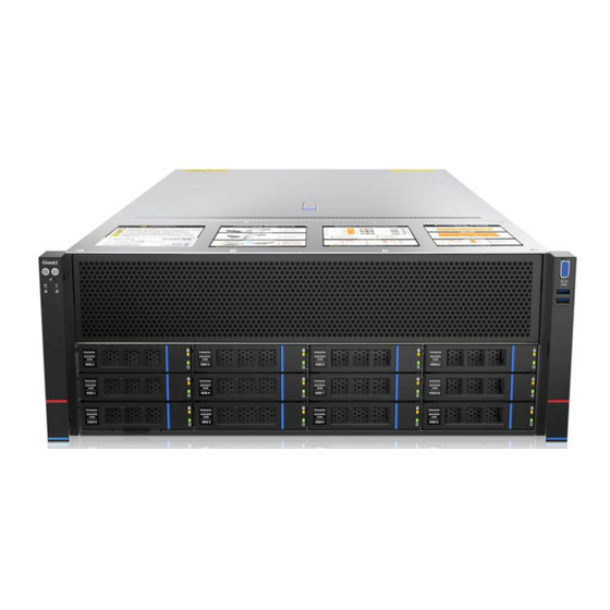
2. Hardware Description 2.1 Front Panel 2.1.1 Appearance 12x3.5-inch hard drive configuration Figure 2-1 24 x 2.5-inch hard drive configuration Figure 2-2 Name Name Right Ear Integrated Left Ear Integrated Assembly Assembly Front Panel Hard Drive Module Table 2-1... -
Page 11: Indicator Lights And Buttons
2.1.2 Indicator lights and buttons Figure 2-3 Indicator light/button Indicator light/button GOOXI Logo M.2 Hard Drive Activity Indicator Power On/Off System Alarm Indicator Button/Indicator UID Button/Indicator Network port 1 connection status indicator light Network port 2 connection status Reset Server Button... -
Page 12: Interface
UID button description: Short press this button to turn on/off the positioning light. Reset server Press to restart the server button Hard drive If there is data read or write activity on the PCH, indicator the hard drive indicator will blink. System warning indicator. -
Page 13: Rear Panel
2.2 Rear Panel 2.2.1 Appearance Appearance of the rear panel Figure 2-5 Name Name PCIe Rear Panel RJ45 10 Gigabit Ethernet Port Power Module USB 3.0 Interface VGA Interface Management Network Port IO Board Table 2-5 Note: The rear window of this product can be customized according to requirements. ... -
Page 14: Indicator Lights And Buttons
2.2.2 Indicator lights and buttons Rear Panel Indicators Figure 2-6 Name Name Power module indicator light UID button RJ45 Network Port COM port Connection Status Indicator RJ45 Network Port Data RJ45 Network Port Transmission Status Indicator Connection Status Indicator RJ45 Network Port Data Management Network Port Transmission Status Indicator... -
Page 15: Processor
When configuring with 1 processor, it must be installed in the CPU 0 position. Processors installed in the same server must have the same model. For specific optional system components, please consult Gooxi sales. Processor positions are as shown in the diagram below: ... -
Page 16: Memory Compatibility Information
Figure 2-8 2.4.2 Memory Compatibility Information Note: The same server must use the same model of DDR5 memory, and all memory modules must operate at the same speed. The speed value is the minimum of the following: The memory speed supported by the specific CPU. ... -
Page 17: Storage
Figure 2-9 2.5 Storage 2.5.1 Hard drive configuration Configuration 4U 12-bay 4U 24-bay Description SAS hard drives Supports 24 Maximum 12 hot-swappable require an hot-swappable Front Hard 3.5/2.5-inch optional SAS 2.5-inch Drive SAS/SATA/NVM passthrough card SAS/SATA/NV Quantity e hard drives or RAID card for Me hard drives support... -
Page 18: Hard Drive Status Indicator
When configuring 4 power modules, supports 3+1 or 2+2 redundant backup. Power modules in the same server must have the same model. For specific optional system accessories, please consult Gooxi sales. The power module locations are as shown in the following diagram: ... -
Page 19: Fans
Figure 2-13 The device is equipped with two identical specification hot-swappable power modules, both of which must be powered simultaneously for the product to function properly. 2.7 Fans The chassis supports 12 fan modules internally. Supports hot swapping. Supports operation with a single fan failure. -
Page 20: I/O Expansion
2.8 I/O Expansion 2.8.1 PCIe slot location Figure 2-15 12-Bay Direct Connection Configuration 1: Provides slot 1 to slot 13, with a total of 13 PCIe slots. Slots 2 to 5 and slots 10 to 13 support dual-width GPUs, while slots 1, 7, and 8 support single-width PCIe cards. -
Page 21: Pcba
card. ◆Half-height, half-length PCIe slots are backward compatible with half-height, half-length PCIe cards. ◆The power supply capability of all slots can support PCIe cards with a maximum power of 75W. The power of PCIe cards depends on the model of the PCIe card. Table 2-11 2.9 PCBA 2.9.1 Motherboard... -
Page 22: Hard Drive Backplane
NCSI connector AUX power connector USB3.0 connector Right ear board connector 19、22 PCIE Riser card power connector 20、26 Front hard drive backplane power connector 21、25 Fan board power connector Fan board data connector Table 2-12 2.9.2 Hard drive backplane 12×3.5-inch Front Hard Drive Backplane ... - Page 23 mainly used indicator CPLD chip control of NVME SSD and SAS/SATA HDD providing PCIe×8 interface for MCIO connector connecting to CPU and NVME Table 2-14 8×2.5-inch Front Hard Drive Backplane TOP surface Figure 2-19 Description Function SAS/SATA/NVME hard Supports 8 SATA/SAS/NVMe drive connector drives, supports PCIe 5.0 speeds Table 2-15...
-
Page 24: Installation Instructions
Figure 2-20 Description Function MCIO interface NVME drive signal cable interface SlimSASx4 interface SATA drive signal cable interface Backplane power transmission 5pin interface connector Table 2-16 3. Installation Instructions... -
Page 25: Chassis Top Cover Installation
3.1 Chassis Top Cover Installation Step 1: Lift the slot at the opening position, push and lift it in the direction indicated by the diagram. Figure 3-1 3.2 Installation of Accessories 3.2.1 CPU installation Step 1: Install the retention clip, tilt the CPU at the angle shown in the ... -
Page 26: Heatsink Installation
Figure 3-3 3.2.2 Heatsink installation Step 1: Remove the motherboard processor socket cover plate. Figure 3-4 Step 2: Install the CPU and heatsink onto the motherboard. Align the heatsink mounting screws on the heatsink base with the fixed screws ... -
Page 27: Memory Installation
Figure 3-5 Note: The pins on the motherboard are very fragile and can easily be damaged. To prevent damage to the motherboard, do not touch the processor or the processor socket contacts. 3.2.3 Memory installation The 16 memory slots controlled by CPU0 on the motherboard are:DIMM_A0、DIMM_A1、 DIMM_B0、DIMM_B1、DIMM_C0、DIMM_C1、DIMM_D0、DIMM_D1、DIMM_E0、... -
Page 28: Card Installation
Figure 3-7 Note: Please use memory modules with the same CAS latency value on this motherboard. We recommend using memory modules of the same capacity, frequency, and manufacturer for optimal compatibility. It is important to note that: In the same channel, memory modules with larger capacities must be installed in the first slot. -
Page 29: Server Slide Rail Installation
Figure 3-9 3.2.6 Server slide rail installation Step 1: Prepare two slide rails and pull out the inner rail. Figure 3-10 Step 2: Fasten the inner rails to the sides of the chassis. ... - Page 30 Figure 3-11 Step 3: Install the outer rails on the cabinet brackets and secure the screws. Figure 3-12 Note: When installing the guide rail, align it with the U-mark, and push it into place until you hear a click sound. Secure it firmly using M5 screws. Step 4: Align the chassis with the inner rails installed with the outer rails for ...
- Page 31 continue to push the chassis gently. Step 5: Push the chassis forward until it cannot slide and make sure that the screws are securely installed to complete the installation. Figure 3-14 Note: During equipment maintenance, it is necessary to loosen the panel screws and pull the chassis lightly.
-
Page 32: Configuration Instructions
4. Configuration Instructions 4.1 Initial Configuration 4.1.1 Power on and start Before powering on, it is necessary to ensure that all configurations of the server are installed in accordance with the corresponding specifications and standards, and keep the server turned off but not unplugged from the power supply. - Page 33 Figure 4-1 State After G3 The menu options for setting the state after entering G3 status are: S0 State:Power on and start up directly S5 State:You need to press the Power button to turn on the power Default: S5 State Enter the BMC IP address ->...
-
Page 34: Initial Data
Figure 4-2 For detailed usage of BMC and BIOS, please refer to the corresponding user manual. 4.1.2 Initial data BMC default account: admin BMC default password: Gooxi@123. BMC default address: 192.168.100.1 BIOS Default Password: None 4.1.3 Configure BIOS Press the <DEL>... -
Page 35: Configure Bmc
Figure 4-3 The Main interface contains the basic information of the BIOS system, such as the BIOS version number, CPU model, memory capacity, and the system time can be set. For detailed instructions, please refer to the "BIOS User Manual". Navigation key description: ... - Page 36 address is displayed. After the server powers on, pay attention to the POST process. Press the <DEL> or <ESC> key on the keyboard to enter the BIOS Setup interface. Switch to the following screen: Figure 4-4 Configure IPV4 support: Configuration Address source ...
- Page 37 Configuration Address source Configure the BMC IP address allocation mode, the menu options are: Unspecified: No change to BMC parameters Static: BIOS static IP setting DynamicBmcDhcp: BMC runs DHCP to dynamically assign IP DynamicBmcNonDhcp: BMC runs the Non-DHCP protocol to dynamically assign IP Default: Unspecified When changing from "Unspecified"...
- Page 38 will display the network parameters (IPv6) for the system's dedicated Ethernet port. Log in to the BMC management interface Enter the IP address on the web page, as shown in the figure: Figure 4-5 Enter the account password to enter the home page, and you can set the BMC IP address on the management interface.
- Page 39 Figure 4-6 This page sets the IP address of the BMC management network port.
-
Page 40: Appendix
If the above steps do not resolve the issue, try replacing the monitor with a known working one to confirm if the original monitor is faulty. If the issue persists, please contact Gooxi's customer service department for resolution. Front Panel Indicator Lights Alarm Refer to the instructions in the manual to determine the specific alarm information indicated by the front panel lights and buttons. - Page 41 Set static or dynamic IP and ensure ping connectivity. If the web interface does not open, try using a newer version of Internet Explorer. If the problem is not resolved, please contact Gooxi’s customer service department for further assistance and resolution.
-
Page 42: Scrap Recycling
6. Scrap Recycling For environmental protection and resource reuse, we earnestly ask you to properly handle discarded server products. Before discarding the server, we recommend that you completely demagnetize the storage media, clear data, and physically destroy them to ensure that your personal data is not leaked.
Need help?
Do you have a question about the SY4108G-G4 and is the answer not in the manual?
Questions and answers