
Related Manuals for DFI CMS631-H420E


Summary of Contents for DFI CMS631-H420E
- Page 1 CMS631-Q470E/H420E ATX Industrial Motherboard User’s Manual © December 27, 2023 DFI Inc.
- Page 2 Copyright FCC and DOC Statement on Class B This publication contains information that is protected by copyright. No part of it may be repro- This equipment has been tested and found to comply with the limits for a Class B digital duced in any form or by any means or used to make any transformation/adaptation without the device, pursuant to Part 15 of the FCC rules.
-
Page 3: Table Of Contents
Table of Contents Serial Port Console Redirection ...................33 Serial Port Console Redirection ► Console Redirection Settings ......34 USB Configuration ......................34 Chapter 1 - Introduction........................ 6 Network Stack Configuration..................35 CSM Configuration ......................35 Specifications ......................... 6 USB Power Control ......................36 Dimensions ..........................8 Block Diagram ........................ - Page 4 About this Manual Static Electricity Precautions This manual can be downloaded from the website. It is quite easy to inadvertently damage your PC, system board, components or devices even before installing them in your system unit. Static electrical discharge can damage computer The manual is subject to change and update without notice, and may be based on editions that components without causing any signs of physical damage.
- Page 5 Before Using the System Board About the Package When installing the system board in a new system, you will need at least the following internal The package contains the following items. If any of these items are missing or damaged, components.
-
Page 6: Chapter 1 - Introduction
Chapter 1 INTRODUCTION Chapter 1 - Introduction EXPANSION Interface 1 x PCIe x16 (Gen 3) 1 x PCIe x4 (Gen 3) 5 x PCI ▲ Specifications Q470E: 1 x M.2 2242/2260/2280 M key (PCIe Gen3 x4 NVMe/SATA/Intel ® Optane Memory support) SYSTEM Processor 10th Generation Intel... - Page 7 Chapter 1 INTRODUCTION MECHANICAL Dimensions ATX Form Factor Audio 1 x Front Audio Header 305mm (12") x 244mm (9.6") 1 x S/PDIF Height PCB: 1.6mm SATA Q470E: 6 x SATA 3.0 (up to 6Gb/s) RAID 0/1/5/10 Top Side: 37.7mm one SATA port shares with M.2 M-key Bottom Side: 3mm H420E: 4 x SATA 3.0 (up to 6Gb/s) Certifications...
-
Page 8: Dimensions
Chapter 1 INTRODUCTION ▲ Dimensions ▲ Block Diagram User's Manual | CMS631-Q470E/H420E... -
Page 9: Chapter 2 - Hardware Installation
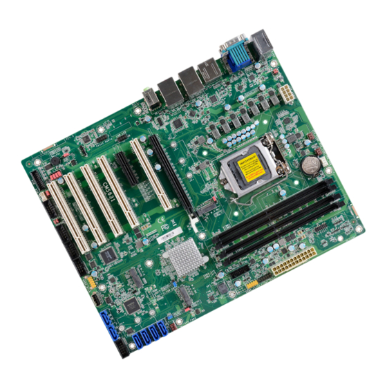
Chapter 2 HARDWARE INSTALLATION Chapter 2 - Hardware Installation ▲ Board Layout Note: Some components are optional and only available upon request. System Fan 1 Important: CPU Fan System Fan 2 Electrostatic discharge (ESD) can damage your board, processor, disk drives, DDR4_1 DDR4_3 add-in boards, and other components. -
Page 10: System Memory
Chapter 2 HARDWARE INSTALLATION ▲ System Memory ▲ System Memory Installing the DIMM Module System Fan 1 System Fan 2 CPU Fan DDR4_1 DDR4_3 +12V Power Before installing the memory module, please make sure that the following safety cautions are USB7/8 well-attended. -
Page 11: Removing The Dimm Module
Chapter 2 HARDWARE INSTALLATION ▲ System Memory ▲ Installing the DIMM Module ▲ System Memory Removing the DIMM Module Please follow the steps below to install the memory card into the socket. Please follow the steps below to remove the memory card from the socket. Step 1: Press the eject tabs at both ends of the socket outward and downward to release them from Step 1:... -
Page 12: Cpu
Chapter 2 HARDWARE INSTALLATION ▲ CPU Installing the CPU Fan and Heat Sink The CPU must be kept cool by using a CPU fan with heat sink. Without sufficient air circula- tion across the CPU and heat sink, the CPU will overheat damaging both the CPU and system board. -
Page 13: Jumper Settings
Chapter 2 HARDWARE INSTALLATION ▲ Jumper Settings Clear CMOS Data (JP5) COM1/COM2 RS232 Power Select (JP4&JP7) System Fan 1 CPU Fan System Fan 2 DDR4_3 DDR4_1 +12V Power USB7/8 Battery COM1 Socket LGA1200 System Fan 1 CPU Fan System Fan 2 (COM 1) DDR4_3 DDR4_1... -
Page 14: Dio Power & Voltage (Jp11/12/13/14/15)
Chapter 2 HARDWARE INSTALLATION AT/ATX Mode (JP26) DIO Power & Voltage (JP11/12/13/14/15) System Fan 1 CPU Fan System Fan 2 System Fan 1 System Fan 2 CPU Fan DDR4_3 DDR4_1 +12V Power DDR4_1 DDR4_3 USB7/8 +12V Power USB7/8 Battery Battery COM1 Socket LGA1200 COM1... -
Page 15: Connector Power Control (Jp27&Jp28)
Chapter 2 HARDWARE INSTALLATION ▲ Pin Assignment M.2 Connector Power Control (JP27&JP28) InnoAGE HDR1 (JP24) System Fan 1 System Fan 1 System Fan 2 CPU Fan System Fan 2 CPU Fan DDR4_1 DDR4_3 DDR4_1 DDR4_3 +12V Power +12V Power USB7/8 USB7/8 Battery Battery... -
Page 16: Usb Ports
Chapter 2 HARDWARE INSTALLATION USB Ports „ USB 2.0 9/10 & 11/12 (UBJ4 & UBJ1) System Fan 1 Assignment Assignment System Fan 2 CPU Fan USB 7/8 (USB 2.0) DDR4_1 DDR4_3 +12V Power USB7/8 Battery COM1 Socket LGA1200 Data- Data- DP++ HDMI ATX Power... -
Page 17: Graphics Interfaces
Chapter 2 HARDWARE INSTALLATION Graphics Interfaces COM1 The display ports consist of the following: System Fan 1 System Fan 2 CPU Fan DDR4_1 DDR4_3 System Fan 1 • 1 DP++ Port +12V Power System Fan 2 CPU Fan USB7/8 DDR4_1 DDR4_3 Battery +12V Power... -
Page 18: Rj45 Lan Ports
Chapter 2 HARDWARE INSTALLATION RJ45 LAN Ports Audio System Fan 1 System Fan 2 CPU Fan DDR4_1 DDR4_3 +12V Power USB7/8 System Fan 1 Battery System Fan 2 CPU Fan COM1 DDR4_1 DDR4_3 Socket LGA1200 +12V Power USB7/8 Battery Rear Audio COM1 Socket LGA1200 DP++... -
Page 19: Internal I/O Connectors
Chapter 2 HARDWARE INSTALLATION ▲ Internal I/O Connectors ▲ Internal I/O Connectors Digital I/O Connector (J2) System Fan 1 SATA -Serial ATA (J31, J32, J17, J23, J24, J25) System Fan 2 CPU Fan DDR4_1 DDR4_3 +12V Power USB7/8 System Fan 1 Battery System Fan 2 CPU Fan... -
Page 20: Com Ports (J9, J11, J13, J15, J16)
Chapter 2 HARDWARE INSTALLATION ▲ Internal I/O Connectors COM Ports (J9, J11, J13, J15, J16) Connecting External Serial Ports System Fan 1 System Fan 2 CPU Fan Your COM port may come mounted on a card-edge bracket. Install the card-edge bracket to DDR4_1 DDR4_3 +12V Power... -
Page 21: Cooling Fan Connectors
Chapter 2 HARDWARE INSTALLATION ▲ Internal I/O Connectors ▲ Internal I/O Connectors Cooling Fan Connectors Power Connector System Fan 1 (J7) „ ATX 8-pin Power Connectors System Fan 2 (J22) CPU Fan (J8) System Fan 1 System Fan 2 CPU Fan DDR4_3 DDR4_1 +12V... -
Page 22: Front Panel (J18)
Chapter 2 HARDWARE INSTALLATION ▲ Internal I/O Connectors ▲ Internal I/O Connectors Front Panel (J18) S/PDIF Connector (AUJ1) System Fan 1 System Fan 2 CPU Fan DDR4_1 DDR4_3 +12V Power USB7/8 „ Front Panel Connector Battery System Fan 1 System Fan 2 CPU Fan COM1 Socket LGA1200... -
Page 23: Lpc Connector (J21)
Chapter 2 HARDWARE INSTALLATION ▲ Internal I/O Connectors ▲ Internal I/O Connectors LPC Connector (J21) Innoage HDD Power (CN37) „ LPC Connector System Fan 1 System Fan 2 CPU Fan System Fan 1 System Fan 2 CPU Fan DDR4_1 DDR4_3 +12V Power DDR4_1 DDR4_3... -
Page 24: Expansion Slots
Chapter 2 HARDWARE INSTALLATION ▲ Expansion Slots ▲ Internal I/O Connectors Expansion Slots Installing the M.2 Module System Fan 1 System Fan 2 CPU Fan DDR4_1 DDR4_3 +12V Power USB7/8 Before installing the M.2 module into the M.2 socket, please make sure that the following Battery PCIe 1 (PCIe x16) COM1... -
Page 25: Battery
Chapter 2 HARDWARE INSTALLATION ▲ Internal I/O Connectors Battery System Fan 1 System Fan 2 CPU Fan Please follow the steps below to install the card into the socket. DDR4_1 DDR4_3 +12V Power USB7/8 „ Battery Battery COM1 Socket LGA1200 DP++ Step 1: HDMI... -
Page 26: Chapter 4 - Bios Settings
Chapter 3 BIOS SETTINGS Chapter 4 - BIOS Settings ▲ Overview Legends The BIOS is a program that takes care of the basic level of communication between the CPU Keys Function and peripherals. It contains codes for various advanced features found in this system board. The BIOS allows you to configure the system and save the configuration in a battery-backed Right / Left arrow CMOS so that the data retains even when the power is off. -
Page 27: Main
Chapter 3 BIOS SETTINGS ▲ Main ▲ Advanced The Main menu is the first screen that you will see when you enter the BIOS Setup Utility. The Advanced menu allows you to configure your system for basic operation. Some entries are defaults required by the system board, while others, if enabled, will improve the performance of your system or let you set some features according to your preference. -
Page 28: Rc Acpi Configuration
Chapter 3 BIOS SETTINGS ▲ Advanced ▲ Advanced RC ACPI Configuration CPU Configuration Intel (VMX) Virtualization Technology Wake system from S5 via RTC When this field is set to Enabled, the VMM can utilize the additional hardware capabilities pro- When Enabled, the system will automatically power up at a designated time every day. Once it’s vided by Vanderpool Technology. -
Page 29: Power & Performance
Chapter 3 BIOS SETTINGS ▲ Advanced ▲ Advanced Power & Performance PCH-FW Configuration ME State When this field is set to Disabled, ME will be put into ME Temporarily Disabled Mode. Intel (R) SpeedStep(tm) Manageability Features State This field is used to enable or disable the Intel SpeedStep® Technology, which helps optimize Enable or disable Intel(R) Manageability features. -
Page 30: Trusted Computing
Chapter 3 BIOS SETTINGS ▲ Advanced ▲ Advanced Trusted Computing NCT6126D Super IO Configuration Security Device Support WatchDog Output Options This field is used to enable or disable BIOS support for the security device such as an TPM 2.0 Select The Output Options. to achieve hardware-level security via cryptographic keys. -
Page 31: Nct6126D Super Io Configuration ► Serial Port 1,2 Configuration
Chapter 3 BIOS SETTINGS ▲ Advanced ▲ Advanced NCT6126D Super IO Configuration NCT6126D Super IO Configuration ► Serial Port 1,2 Configuration ► Serial Port 3,4 Configuration Serial Port Serial Port Enable or disable serial port. Enable or disable serial port. RS485 Auto Flow Set Serial RS485 Auto Flow. -
Page 32: Nct6126D Super Io Configuration ► Serial Port 5,6 Configuration
Chapter 3 BIOS SETTINGS ▲ Advanced ▲ Advanced NCT6126D Super IO Configuration ► Serial Port 5,6 Configuration NCT6126D HW Monitor This section displays the system’s health information, i.e. voltage readings, CPU and system temperatures, and fan speed readings Serial Port Enable or disable serial port. -
Page 33: Serial Port Console Redirection
Chapter 3 BIOS SETTINGS ▲ Advanced ▲ Advanced Serial Port Console Redirection NCT6126D HW Monitor ► Smart FAN Function Smart Fan is a fan speed moderation strategy dependent on the current system temperature. When the system temperature goes higher than the Boundary setting, the fan speed will be turned up to the setting of the Fan Speed Count that bears the same index as the Boundary field. -
Page 34: Serial Port Console Redirection ► Console Redirection Settings
Chapter 3 BIOS SETTINGS ▲ Advanced ▲ Advanced USB Configuration Serial Port Console Redirection ► Console Redirection Settings Configure the serial settings of the current COM port. Legacy USB Support • Enabled Enable Legacy USB support. Terminal Type Select terminal type: VT100, VT100+, VT-UTF8 or ANSI. •... -
Page 35: Network Stack Configuration
Chapter 3 BIOS SETTINGS ▲ Advanced ▲ Advanced Network Stack Configuration CSM Configuration Network Stack CSM (Compatibility Support Module) Support Enable or disable (Default) UEFI network stack. The following fields will appear when this field Enable or disable CSM Support. is enabled. -
Page 36: Usb Power Control
Chapter 3 BIOS SETTINGS ▲ Advanced USB Power Control USB Power 5V_Dual: Support system wake from S3/S4 by USB KB&MS 5V: No Support system wake from S3/S4 by USB KB&MS User's Manual | CMS631-Q470E/H420E... -
Page 37: Chipset
Chapter 3 BIOS SETTINGS ▲ Chipset ▲ Chipset Graphics Configuration Primary Display Select which of IGFX/PEG/PCI Graphics device to be the primary display. Internal Graphics Keep IGFX "Enabled" or "Disabled" based on the setup options, or select "Auto" for auto-detec- tion. -
Page 38: Peg Port Configuration
Chapter 3 BIOS SETTINGS ▲ Chipset ▲ Chipset PEG Port Configuration PEG Port Configuration ► PEG Port Feature Configuration Detect Non-Compliance Device Enable Root Port Detect Non-Compliance PCI Express Device in PEG Enable/Disable the Root Port Max Link Speed Configure PEG 0:1:0 Max Speed User's Manual | CMS631-Q470E/H420E... -
Page 39: Pch-Io Configuration
Chapter 3 BIOS SETTINGS ▲ Chipset PCH-IO Configuration PCI Express Configuration PCI Express Configuration Settings SATA And RST Configuration SATA Device Otpions Settings HD Audio Configuration HD Audio Subsystem Configuration Settings LAN1(I219) Enable or disable onboard NIC. Wake on LAN Enable Enable or disable integrated LAN to wake the system. -
Page 40: Pch-Io Configuration ► Pci Express Configuration
Chapter 3 BIOS SETTINGS ▲ Chipset ▲ Chipset PCH-IO Configuration PCH-IO Configuration ► PCI Express Configuration ► SATA And RST Configuration SATA Controller(s) Select one of the PCI Express channels and press enter to configure the following settings. This field is used to enable or disable the Serial ATA controller. LAN 2 &... -
Page 41: Pch-Io Configuration ► Hd Audio Configuration
Chapter 3 BIOS SETTINGS ▲ Chipset PCH-IO Configuration ► HD Audio Configuration HD Audio Control the detection of the HD Audio device. Disabled HDA will be unconditionally disabled. Enabled HDA will be unconditionally enabled. User's Manual | CMS631-Q470E/H420E... -
Page 42: Security
Chapter 3 BIOS SETTINGS ▲ Security ▲ Security Secure Boot Administrator Password Secure Boot Set the administrator password. To clear the password, input nothing and press enter when a Secure Boot feature is Active if secure Boot is Enabled, Platform Key (PK) is enrolled and the new password is asked. -
Page 43: Boot
Chapter 3 BIOS SETTINGS ▲ Boot ▲ Save & Exit Save Changes and Reset Setup Prompt Timeout To save the changes, select this field and then press <Enter>. A dialog box will appear. Select Set the number of seconds to wait for the setup activation key. 65535 (0xFFFF) denotes indefi- Yes to reset the system after saving all changes made. -
Page 44: Updating The Bios
Chapter 3 BIOS SETTINGS ▲ Updating the BIOS To update the BIOS, you will need the new BIOS file and a flash utility. Please contact technical support or your sales representative for the files and specific instructions about how to update BIOS with the flash utility.
Need help?
Do you have a question about the CMS631-H420E and is the answer not in the manual?
Questions and answers