Table of Contents
Advertisement
Quick Links
Advertisement
Table of Contents

Subscribe to Our Youtube Channel
Related Manuals for DFI CMS631-Q470E/H420E


Summary of Contents for DFI CMS631-Q470E/H420E
- Page 1 CMS631-Q470E/H420E ATX Industrial Motherboard User’s Manual A-624-M-2126...
- Page 2 Copyright FCC and DOC Statement on Class B This publication contains information that is protected by copyright. No part of it may be repro- This equipment has been tested and found to comply with the limits for a Class B digital duced in any form or by any means or used to make any transformation/adaptation without the device, pursuant to Part 15 of the FCC rules.
-
Page 3: Table Of Contents
Table of Contents MEBX Configuration ......................38 Debug Configuration .....................39 UEFI Device Manager ....................39 Chapter 1 - Introduction........................ 6 SIO NCT6126D .......................40 Console Redirection ......................42 Specifications ......................... 6 Features ..........................8 Security ..........................43 Block Diagram ........................9 Boot ............................43 Exit ............................45 Chapter 2 - Hardware Installation .................... - Page 4 About this Manual Static Electricity Precautions This manual can be downloaded from the website. It is quite easy to inadvertently damage your PC, system board, components or devices even before installing them in your system unit. Static electrical discharge can damage computer The manual is subject to change and update without notice, and may be based on editions that components without causing any signs of physical damage.
- Page 5 About the Package When installing the system board in a new system, you will need at least the following internal components. The package contains the following items. If any of these items are missing or damaged, please contact your dealer or sales representative for assistance. •...
- Page 6 Chapter 1 INTRODUCTION Chapter 1 - Introduction EXPANSION Interface 1 x PCIe x16 (Gen 3) 1 x PCIe x4 (Gen 3) 5 x PCI X Specifications Q470E: Up to 2 x M.2 2242/2260/2280 M key (PCIe Gen3 x4 NVMe/ SATA/Intel® Optane Memory support, one SYSTEM Processor 10th Generation Intel®...
- Page 7 Chapter 1 INTRODUCTION Audio 1 x Front Audio Header 1 x S/PDIF SATA Q470E: 6 x SATA 3.0 (up to 6Gb/s) RAID 0/1/5/10 H420E: 4 x SATA 3.0 (up to 6Gb/s) 1 x 16-bit DIO 1 x LPC (supports LPC EXT-RS232/RS485 module) SMBus 1 x SMBus PS/2...
-
Page 8: Chapter 1 - Introduction
Chapter 1 INTRODUCTION X Features Watchdog Timer PCI Express The Watchdog Timer function allows your application to regularly “clear” the system at the set PCI Express is a high bandwidth I/O infrastructure that possesses the ability to scale speeds time interval. If the system hangs or fails to function, it will reset at the set time interval so that by forming multiple lanes. - Page 9 Chapter 1 INTRODUCTION X Block Diagram Channel A DDR4 2400/2666/2933MHz UDIMM Channel A PTN3355 DDR4 2400/2666/2933MHz UDIMM (Q470E) Channel B DDR4 2400/2666/2933MHz UDIMM DP++ LGA 1200 Channel B DDR4 2400/2666/2933MHz UDIMM (Q470E) HDMI ASM1442K PCIe x16 Gen3 PCIe x16 1x DMI 3.0 PCIe x4 (Gen3) GLAN I219LM...
-
Page 10: Features
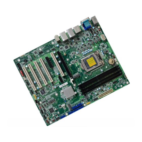
Chapter 2 HARDWARE INSTALLATION Chapter 2 - Hardware Installation X Board Layout Note: Some components are optional and only available upon request. CPU FAN Important: Electrostatic discharge (ESD) can damage your board, processor, disk drives, DDR4_1 DDR4_3 USB7/8 System +12V Power add-in boards, and other components. -
Page 11: Block Diagram
Chapter 2 HARDWARE INSTALLATION X System Memory System Memory Installing the DIMM Module CPU FAN DDR4_1 DDR4_3 USB7/8 System +12V Power Fan 1 Before installing the memory module, please make sure that the following safety cautions are Battery well-attended. Socket LGA1151 COM 1 1. -
Page 12: Removing The Dimm Module
Chapter 2 HARDWARE INSTALLATION System Memory Installing the DIMM Module System Memory Removing the DIMM Module Please follow the steps below to install the memory card into the socket. Please follow the steps below to remove the memory card from the socket. Step 1: Press the eject tabs at both ends of the socket outward and downward to release them from Step 1:... -
Page 13: Cpu
Chapter 2 HARDWARE INSTALLATION X CPU The system board is embedded with a AMD® EPYC™ Embedded CPU. Installing the CPU Fan and Heat Sink The CPU must be kept cool by using a CPU fan with heat sink. Without sufficient air circulation across the CPU and heat sink, the CPU will overheat damaging both the CPU and system board. -
Page 14: Jumper Settings
Chapter 2 HARDWARE INSTALLATION X Jumper Settings CLEAR CMOS Data CPU FAN DDR4_1 DDR4_3 USB7/8 System +12V Power Fan 1 Battery COM 1 Socket LGA1151 HDMI DP++ ATX Power LAN 2 USB3_1/2 USB2_1/2 Front Panel LAN 1 USB3_3/4 USB2_3/4 SPI Flash JP27 Mic-in BIOS... -
Page 15: Com1/Com2 Rs232/422/485 Select
Chapter 2 HARDWARE INSTALLATION Jumper Settings „ JP1/JP2 (COM1), JP6/JP8 (COM2) 2 4 6 2 4 6 2 4 6 COM1/COM2 RS232/422/485 Select 1 3 5 1 3 5 1 3 5 1-3, 2-4 On: 3-5, 4-6 On: 3-5, 4-6 On: RS232 (default) RS422 Full Duplex RS485... -
Page 16: Com1/Com2 Rs232 Power Select
Chapter 2 HARDWARE INSTALLATION Jumper Settings COM1/COM2 RS232 Power Select CPU FAN (COM 1) DDR4_1 DDR4_3 USB7/8 System +12V Power Fan 1 Battery Socket LGA1151 COM 1 HDMI DP++ ATX Power LAN 2 USB3_1/2 USB2_1/2 Front Panel LAN 1 USB3_3/4 USB2_3/4 SPI Flash JP27... -
Page 17: Dio Power & Voltage - Jp11/12/13/14/15
Chapter 2 HARDWARE INSTALLATION Jumper Settings Jumper Settings DIO Power & Voltage - JP11/12/13/14/15 AT/ATX Mode - JP26 CPU FAN CPU FAN DDR4_1 DDR4_3 DDR4_1 DDR4_3 USB7/8 USB7/8 System System +12V Power +12V Power Fan 1 Fan 1 Battery Battery Socket LGA1151 Socket LGA1151 COM 1... -
Page 18: Pwm Control - Jp23
Chapter 2 HARDWARE INSTALLATION Jumper Settings Jumper Settings PWM Control - JP23 InnoAGE HDR1 - JP24 CPU FAN CPU FAN DDR4_3 DDR4_1 USB7/8 System DDR4_1 DDR4_3 +12V Power USB7/8 System +12V Power Fan 1 Fan 1 Battery Battery Socket LGA1151 COM 1 Socket LGA1151 COM 1... -
Page 19: M2 Connector Power Control - Jp27 / Jp28
Chapter 2 HARDWARE INSTALLATION Jumper Settings M.2 Connector Power Control - JP27 / JP28 CPU FAN DDR4_1 DDR4_3 USB7/8 System +12V Power Fan 1 Battery Socket LGA1151 COM 1 HDMI DP++ ATX Power LAN 2 USB3_1/2 USB2_1/2 Front JP27 LAN 1 Panel USB3_3/4 USB2_3/4... -
Page 20: Rear I/O Ports
Chapter 2 HARDWARE INSTALLATION X Rear I/O Ports PS/2 COM 1 HDMI LAN 2 LAN 1 Line-out Mic-in USB 2.0 DP++ USB 3.2 USB 3.2 Gen1 Gen2 The rear panel I/O ports consist of the following: • 1 DP++ • 2 USB 3.2 Gen2 ports •... -
Page 21: Usb Ports
Chapter 2 HARDWARE INSTALLATION Rear I/O Ports „ USB 2.0 Headers (USB 9/10) USB Ports Assignment Assignment USB 7/8 (USB 2.0) CPU FAN DDR4_3 DDR4_1 USB7/8 System +12V Power Fan 1 Data- Data- Battery Socket LGA1151 COM 1 Data+ Data+ HDMI DP++ ATX Power... -
Page 22: Graphics Interfaces
Chapter 2 HARDWARE INSTALLATION Rear I/O Ports Rear I/O Ports COM1 Graphics Interfaces The display ports consist of the following: • 1 DP++ Port CPU FAN CPU FAN DDR4_1 DDR4_3 DDR4_1 DDR4_3 USB7/8 System USB7/8 System +12V Power +12V Power Fan 1 Fan 1 •... -
Page 23: Rj45 Lan Ports
Chapter 2 HARDWARE INSTALLATION Rear I/O Ports Rear I/O Ports RJ45 LAN Ports Audio CPU FAN DDR4_1 DDR4_3 USB7/8 System +12V Power Fan 1 CPU FAN Battery DDR4_1 DDR4_3 USB7/8 System +12V Power COM 1 Socket LGA1151 Fan 1 Battery Rear Audio HDMI Socket LGA1151... -
Page 24: Internal I/O Connectors
Chapter 2 HARDWARE INSTALLATION X Internal I/O Connectors Internal I/O Connectors Digital I/O Connector SATA (Serial ATA) CPU FAN DDR4_1 DDR4_3 USB7/8 System CPU FAN SATA Pin Assignment +12V Power „ Fan 1 DDR4_1 DDR4_3 USB7/8 Battery System +12V Power Fan 1 COM 1 Socket LGA1151... -
Page 25: Com (Serial) Ports
Chapter 2 HARDWARE INSTALLATION Internal I/O Connectors COM (Serial) ports CPU FAN DDR4_3 DDR4_1 The pin functions of COM 2 port will vary according to setting of JP6, JP7, JP8 and JP10. Refer USB7/8 System +12V Power Fan 1 to “COM1/COM2 RS232/422/485 Select” and “COM1/COM2 RS232/Power Select” in this chap- Battery ter for more information. -
Page 26: Cooling Fan Connectors
Chapter 2 HARDWARE INSTALLATION Internal I/O Connectors Internal I/O Connectors Cooling Fan Connectors Power Connector System Fan 1 (PWM) CPU Fan (PWM) „ ATX 8-pin Power Connectors CPU FAN DDR4_1 DDR4_3 USB7/8 System +12V Power Fan 1 +12V Battery COM 1 Socket LGA1151 12 24 CPU FAN... -
Page 27: Front Panel
Chapter 2 HARDWARE INSTALLATION Internal I/O Connectors Internal I/O Connectors Front Panel S/PDIF Connector CPU FAN DDR4_1 DDR4_3 USB7/8 +12V Power System Fan 1 „ Front Panel Connector Battery CPU FAN COM 1 Socket LGA1151 DDR4_1 DDR4_3 USB7/8 System +12V Power Fan 1 PWR-LED ATX-SW Battery... -
Page 28: Lpc Connector
Chapter 2 HARDWARE INSTALLATION Internal I/O Connectors LPC Connector „ LPC Connector CPU FAN DDR4_1 DDR4_3 USB7/8 System +12V Power Fan 1 Battery COM 1 Socket LGA1151 HDMI DP++ ATX Power LAN 2 USB3_1/2 USB2_1/2 Front Panel LAN 1 USB3_3/4 USB2_3/4 SPI Flash JP27... -
Page 29: Innoage Hdd Power Cn37
Chapter 2 HARDWARE INSTALLATION Internal I/O Connectors Innoage HDD Power CN37 CPU FAN DDR4_1 DDR4_3 USB7/8 System +12V Power Fan 1 Battery Socket LGA1151 COM 1 HDMI DP++ ATX Power LAN 2 USB3_1/2 USB2_1/2 Front LAN 1 Panel USB3_3/4 USB2_3/4 SPI Flash JP27 Mic-in... -
Page 30: Expansion Slots
Chapter 2 HARDWARE INSTALLATION Internal I/O Connectors Internal I/O Connectors Expansion Slots Expansion Slots Installing the M.2 Module CPU FAN Before installing the M.2 module into the M.2 socket, please make sure that the following DDR4_1 DDR4_3 USB7/8 System +12V Power Fan 1 safety cautions are well-attended. -
Page 31: Battery
Chapter 2 HARDWARE INSTALLATION Internal I/O Connectors Expansion Slots Internal I/O Connectors Battery CPU FAN Please follow the steps below to install the card into the socket. DDR4_1 DDR4_3 USB7/8 System +12V Power Fan 1 „ Battery Battery Socket LGA1151 COM 1 HDMI DP++... -
Page 32: Chapter 3 - Bios Setup
Chapter 3 BIOS SETTINGS Chapter 3 - BIOS Setup X Overview Legends The BIOS is a program that takes care of the basic level of communication between the CPU Keys Function and peripherals. It contains codes for various advanced features found in this system board. The BIOS allows you to configure the system and save the configuration in a battery-backed Right / Left arrow Move the highlight left or right to select a menu... -
Page 33: Main
Chapter 3 BIOS SETTINGS X Main X Advanced The Main menu is the first screen that you will see when you enter the BIOS Setup Utility. The Advanced menu allows you to configure your system for basic operation. Some entries are defaults required by the system board, while others, if enabled, will improve the performance of your system or let you set some features according to your preference. -
Page 34: Acpi Configuration
Chapter 3 BIOS SETTINGS Advanced ACPI Configuration InsydeH2O Setup Utility Rev. 5.0 InsydeH2O Setup Utility Rev. 5.0 Advanced Advanced Wake on RTC from S4/S5 ACPI Configuration ACPI Configuration Determines the action tak- in everyday. It will over- en when the system power ride the OS schedule for Wake On LAN <Enabled>... -
Page 35: Cpu Configuration
Chapter 3 BIOS SETTINGS Advanced Advanced CPU Configuration Video Configuration Configure CPU processing related settings in this page. InsydeH2O Setup Utility Rev. 5.0 InsydeH2O Setup Utility Rev. 5.0 Advanced Advanced Initial priority: Video Configuration CPU Configuration Allow more than two fre- AUTO: quency ranges to be sup- PEG->PCIe->PCI->IGFX... -
Page 36: Audio Configuration
Chapter 3 BIOS SETTINGS Advanced Advanced Audio Configuration SATA Configuration InsydeH2O Setup Utility Rev. 5.0 InsydeH2O Setup Utility Rev. 5.0 Advanced Advanced SATA Configuration Control Detection of the SATA Configuration Enable or Disable SATA HD-Audio device. Device. HD Audio <Enabled> SATA Controller(s) <Enabled>... -
Page 37: Usb Configuration
Chapter 3 BIOS SETTINGS Advanced Advanced USB Configuration USB Power Control InsydeH2O Setup Utility Rev. 5.0 InsydeH2O Setup Utility Rev. 5.0 Advanced Advanced U S B k e y b o a r d / m o u s e / s t o r a g e 5V_Dual: Support system wake USB Configuration USB Power Control... -
Page 38: Pci Express Configuration
Chapter 3 BIOS SETTINGS Advanced PCI Express Configuration ►M.2-M1/LAN1/M.2-E/M.2-M2 InsydeH2O Setup Utility Rev. 5.0 Advanced Port Enable PCI Express Configuration PCI Express Port Settings Enable or disable the PCI Express Root Port, LAN Port and M.2-M. ►PCIE1 ►PCIE3 ►LAN2 PCIe Speed ►M.2-M1 ►LAN1 Select PCIe Speed of the current port —... -
Page 39: System Agent (Sa) Configuration
Chapter 3 BIOS SETTINGS Advanced Advanced System Agent (SA) Configuration ME Configuration InsydeH2O Setup Utility Rev. 5.0 InsydeH2O Setup Utility Rev. 5.0 Advanced Advanced U S B k e y b o a r d / m o u s e / s t o r a g e When Disabled ME will be put System Agent (SA) Configuration USB Configuration... -
Page 40: Mebx Configuration
Chapter 3 BIOS SETTINGS Advanced Advanced Active Management Technology Support MEBX Configuration InsydeH2O Setup Utility Rev. 5.0 InsydeH2O Setup Utility Rev. 5.0 Advanced Advanced Enable/Disable Intel(R) Active MEBX Configuration Setting Active Management Technology Support MEBX Configuration Management Technology BIOS Extension. Note : iAMT H/W is Intel AMT Support <Enabled>... -
Page 41: Debug Configuration
Chapter 3 BIOS SETTINGS Advanced Advanced Debug Configuration UEFI Device Manager This section configures Debug setting. Configure UEFI device with option ROM, such as LAN card, etc. InsydeH2O Setup Utility Rev. 5.0 InsydeH2O Setup Utility Rev. 5.0 Advanced Advanced Enable it to output debug mes- UEFI Device Manager Setting Debug Configuration UEFI Device Manager... -
Page 42: Sio Nct6126D
Chapter 3 BIOS SETTINGS Advanced SIO NCT6126D Configure Super I/O settings in this submenu. Scroll by moving the cursor up or down to reveal more options. InsydeH2O Setup Utility Rev. 5.0 InsydeH2O Setup Utility Rev. 5.0 Advanced Advanced Configure Serial port using op- Configure Serial port using op- COM Port 1 <Enable>... - Page 43 Chapter 3 BIOS SETTINGS Advanced SIO NCT6126D X PC Health Status This section displays the PC health status. InsydeH2O Setup Utility Rev. 5.0 InsydeH2O Setup Utility Rev. 5.0 Advanced Advanced PC Health Status Boundary 0 [30] Boundary 1 [40] Voltage Boundary 2 [50] VBAT...
-
Page 44: Console Redirection
Chapter 3 BIOS SETTINGS Advanced Console Redirection X COM1/COM2/COM3/COM4/COM5/COM6 Configure individual COM port serial settings in the submenu. Configure COM port serial settings in the submenu. InsydeH2O Setup Utility Rev. 5.0 InsydeH2O Setup Utility Rev. 5.0 Advanced Advanced E n a b l e C o n s o l e R e d i r e c t i o n Console Redirection Setup COM1 Function... -
Page 45: Security
Chapter 3 BIOS SETTINGS X Security X Boot InsydeH2O Setup Utility Rev. 5.0 InsydeH2O Setup Utility Rev. 5.0 Main Advanced Security Boot Exit Security Current TPM Device <TPM 2.0 (DTPM)> W h e n H i d d e n , d o n ’ t e x - Numlock <Off>... - Page 46 Chapter 3 BIOS SETTINGS Boot PXE Boot capability This field is only available when "Boot Type" is set to “UEFI Boot Type” or “Dual Boot Type”, and when "Network Stack" is enabled. Disabled Suppoort Network Stack UEFI IPv4/IPv6 Legacy Legacy PXE OPROM only USB Boot Enable or disable booting to USB boot devices.
-
Page 47: Exit
BIOS with the flash utility. For updating Insyde BIOS in UEFI mode, you may refer to the how-to video at https://www.dfi.com/tw/knowledge/video/31. InsydeH2O Setup Utility Rev. 5.0... -
Page 48: Chapter 4 - Raid
Chapter 4 RAID SETTINGS Chapter 4 - RAID X Setup Procedure The system board allows configuring RAID on Serial ATA drives. It supports RAID 0, RAID 1, and SPAN. To enable the RAID function, the following settings are required. 1. Install SATA drives. 2. - Page 49 Chapter 4 RAID SETTINGS Setup Procedure Setup Procedure Step 3: Create RAID 0/RAID 1/ SPAN the volume amounts. 1. Select the desired mode and press <Enter>. 4. "*" shown on bottom indicates the progress. 2. Press <Y> to confirm the process. 5.
- Page 50 Chapter 4 RAID SETTINGS tom. Other RAID modes follow the same procedure as well. User's Manual | CMS631...
Need help?
Do you have a question about the CMS631-Q470E/H420E and is the answer not in the manual?
Questions and answers