Table of Contents
Advertisement
Quick Links
Advertisement
Table of Contents

Subscribe to Our Youtube Channel
Related Manuals for DFI CMS100


Summary of Contents for DFI CMS100
- Page 1 CMS100 Mini-ITX User’s Manual © April 11, 2023 DFI Inc.
- Page 2 1. The changes or modifications not expressly approved by the party responsible for com- are the properties of the respective owners. pliance could void the user’s authority to operate the equipment. 2. Shielded interface cables must be used in order to comply with the emission limits. User's Manual | CMS100...
-
Page 3: Table Of Contents
NCT6126D HW Monitor ► Smart FAN Function ..........29 Serial Port Console Redirection ...................30 Serial Port Console Redirection ► Console Redirection Settings ......30 USB Configuration ......................31 Network Stack Configuration..................31 CSM Configuration ......................32 USB Power Control ......................32 User's Manual | CMS100... - Page 4 4. We will not be liable for any indirect, special, incidental or consequential damages to the product that has been modified or altered. User's Manual | CMS100...
- Page 5 Make sure the system is placed or mounted correctly and stably to prevent the chance of dropping or falling may cause damage. • The openings on the system shall not be blocked and shall be kept in distance from User's Manual | CMS100...
-
Page 6: Chapter 1 - Introduction
4096x2160 @ 60Hz 1 x DVI-I (DVI-D signal) DVI-I: resolution up to 1920x1200 @ 60Hz Quad Displays DP++ + DP++ + DVI-I + LVDS/eDP or DP++ + HDMI + DVI-I + LVDS/eDP User's Manual | CMS100... - Page 7 RAID 0/1/5/10 (w/ M.2 Key-M/B slot + 2 SATA Conn., W480E/Q470E only) 1 x 8-bit DIO 1 x DIO Power 1 x LPC WATCHDOG Output & System Reset, Programmable via Software from 1 to 255 Seconds TIMER Interval SECURITY fTPM(Default); dTPM(Opt.) User's Manual | CMS100...
- Page 8 Storage: 5 to 90% RH ENVIRONMENT CS100-Q470: 591,713 hrs @ 25°C; 357,627 hrs @ 45°C ; 234,022 hrs @ 60°C MTBF Calculation model: Telcordia Issue 4 Environment: GB, GC – Ground Benign, Controlled CE, FCC, RoHS CERTIFICATION Certification User's Manual | CMS100...
-
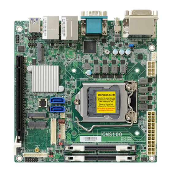
Page 9: Dimensions
Chapter 1 INTRODUCTION X Dimensions X Block Diagram User's Manual | CMS100... -
Page 10: Chapter 2 - Hardware Installations
M.2-M CPU FAN LPC Debugger PCIE1 Clear CMOS M.2-B Battery LVDS SYS FAN Backlight M.2-E Backlight Control Voltage Select SIM1 USB Power Select SO_DIMM1 Inverter Power Voltage Select SO_DIMM2 DIO Power Panel Power Selection Front Panel User's Manual | CMS100... -
Page 11: Jumper Settings
Panel Power SO_DIMM2 Selection DIO Power Front Panel Panel Power Selection Front Panel „ 1-2 On: Normal (Default) „ 2-3 On: Clear CMOS „ 1-2 On: 12V „ 3-4 On: 5V „ 5-6 On: 3.3V (Default) User's Manual | CMS100... -
Page 12: Backlight Voltage Select (Dpjp601)
Voltage Select SO_DIMM2 SO_DIMM2 DIO Power Panel Power DIO Power Panel Power Selection Selection Front Panel Front Panel „ 1-2 On: 3V3 (Default) „ 2-3 On: 5V „ 1-2 On: +12V (Default) „ 2-3 On: 5V User's Manual | CMS100... -
Page 13: At / Atx Mode Select (Jp26)
Voltage Select SO_DIMM2 SO_DIMM2 DIO Power Panel Power DIO Power Selection Panel Power Front Panel Selection Front Panel „ 1-2 On: AT (Default) „ 2-3 On: ATX „ 1-2 On: 5VDU (Default) „ 2-3 On: 5V User's Manual | CMS100... -
Page 14: Pin Assignment
Inverter Power Voltage Select SO_DIMM2 DIO Power Panel Power SO_DIMM2 Selection DIO Power Front Panel Panel Power Selection Front Panel Assignment Assignment Assignment Assignment SBV4 SBV4 MIC2-L USBP_C_11N USBP_C_12N MIC2-R USBP_C_11P USBP_C_12P LINE2-R MIC2-JD LINE2-L LINE2-JD User's Manual | CMS100... -
Page 15: Usb2_7/8 (Ubj8)
Voltage Select Select SO_DIMM1 Inverter Power Voltage Select SO_DIMM2 SO_DIMM2 DIO Power Panel Power Selection DIO Power Panel Power Front Panel Selection Front Panel Assignment Assignment Assignment SBV4 SBV4 USBP_C_7N USBP_C_8N +12V CPUFANIN USBP_C_7P USBP_C_8P CPUFANOUT User's Manual | CMS100... -
Page 16: System Fan (J9)
Select SO_DIMM1 Inverter Power USB Power Voltage Select Select SO_DIMM1 Inverter Power Voltage Select SO_DIMM2 SO_DIMM2 DIO Power Panel Power Selection DIO Power Panel Power Front Panel Selection Front Panel Assignment Assignment Assignment +3.3V SYSFANOUT1 SYSFANIN1 User's Manual | CMS100... -
Page 17: Backlight Control (Dpj601)
Select Voltage Select SO_DIMM1 Inverter Power Voltage Select SO_DIMM2 SO_DIMM2 DIO Power Panel Power DIO Power Selection Panel Power Selection Front Panel Front Panel Assignment Assignment Assignment Assignment +12V 5VDU DIMMING PANEL_PWR LVDS_3V3 BLONOFF VCC_INV_PWR VCC_INV_PWR User's Manual | CMS100... -
Page 18: Dio (J13)
Panel Power Selection Front Panel Front Panel Assignment Assignment Pin Function Assignment Function Pin Assignment D_IOA0_C D_IOA1_C LED POWER D_IOA2_C D_IOA3_C SYS LED LED POWER D_IOA4_C D_IOA5_C HDD LED HD_LED SUSLED D_IOA6_C D_IOA7_C RESET POWER SYS_RST- PWR_BTN- User's Manual | CMS100... -
Page 19: Lpc Debugger (J14)
Chapter 2 HARDWARE INSTALLATION LPC Debugger (J14) LPC Debugger SIM1 Assignment Assignment LAD1 RST# LAD0 FRAME# VCC3 LAD3 LAD2 SERIRQ 5VSB User's Manual | CMS100... -
Page 20: Edp (Cn23)
Chapter 2 HARDWARE INSTALLATION eDP (CN23) Assignment Assignment VCC_INV_PWR VCC_INV_PWR VCC_INV_PWR VCC_INV_PWR DIMMING BLONOFF eDP_GND eDP_GND eDP_GND eDP_GND eDP_HPD_B_R LPC Debugger PANEL_PWR PANEL_PWR PANEL_PWR PANEL_PWR eDP_AUXN_C eDP_AUXP_C SIM1 eDP_LANE0_P eDP_LANE0_N eDP_LANE1_P eDP_LANE1_N eDP_LANE2_P eDP_LANE2_N eDP_LANE3_P eDP_LANE3_N User's Manual | CMS100... -
Page 21: Expansion Slots
Screw tight the card onto the stand-off with a screw driver and a stand-off screw until the gap between the card and the stand-off closes up. The card should be lying parallel to the board when it’s correctly mounted. User's Manual | CMS100... -
Page 22: Installing The So-Dimm Module
Inspect that the clip sits in the notch. If not, please pull the clips outward, release and remove the card, and mount it again. Step 3 4 5 ° User's Manual | CMS100 Step 1... -
Page 23: Chapter 3 - Bios Settings
When “X” appears on the left of a particular field, it indicates that a submenu which contains additional options are available for that field. To display the submenu, move the highlight to that field and press <Enter>. User's Manual | CMS100... -
Page 24: Main
The time format is <hour>, <minute>, <second>. The time is based on the 24-hour military-time clock. For example, 1 p.m. is 13:00:00. Hour displays hours from 00 to 23. Minute displays min- utes from 00 to 59. Second displays seconds from 00 to 59. User's Manual | CMS100... -
Page 25: Rc Acpi Settings
The system automatically powers on after power failure. • S5 State The system enter soft-off state after power failure. Power-on signal input is required to power up the system. • Last State The system returns to the last state right before power failure. User's Manual | CMS100... -
Page 26: Power & Performance
Enable or disable turbo mode of the processor. This field will only be displayed when EIST is enabled. C states Enable or disable CPU Power Management. It allows CPU to enter "C states" when it’s idle and nothing is executing. Note: The sub-menus are detailed in following sections. User's Manual | CMS100... -
Page 27: Trusted Computing
Select the color depth of the LCD Panel — VESA 24bpp, JEIDA 24bpp, VESA and JEIDA 18 bpp. LVDS Bus Mode Select PTN3460 LVDS BUS Mode : Single LVDS Bus /Dual LVDS Bus Note: The configuration must match the specifications of your LCD Panel in order for the LCD Panel to display properly. User's Manual | CMS100... -
Page 28: Nct6126D Super Io Configuration
WatchDog Timer Unit Select WatchDog Timer Unit — Second or Minute. SuperIO WatchDog Timer Set SuperIO WatchDog Timer Timeout value. The range is from 0 (disabled) to 255. Note: The sub-menus are detailed in following sections. User's Manual | CMS100... -
Page 29: Nct6126D Hw Monitor
Fan Speed Count 1 field. • Fan Speed Count 1 to Fan Speed Count 4 Set the fan speed, the value ranging from 1-100%, 100% being full speed. The fans will operate according to the specified boundary temperatures above-mentioned. User's Manual | CMS100... -
Page 30: Serial Port Console Redirection
Select parity bits: None, Even, Odd, Mark or Space. Stop Bits Select stop bits: 1 bit or 2 bits. Flow Control Select flow control type: None or Hardware RTS/CTS. Flow Control is for RS485 mode and is only supported by Serial Port 1 (COM1). User's Manual | CMS100... -
Page 31: Usb Configuration
Enables I/0 port 60h/64h emulation support. This should be enabled for the complete USB Set the number of times the presence of media will be checked. Use either +/- or numeric keyboard legacy support for non-USB aware Oses. keys to set the value. User's Manual | CMS100... -
Page 32: Csm Configuration
This field controls the execution of UEFI and Legacy Storage OpROM. Video This field controls the execution of UEFI and Legacy Video OpROM. Other PCI devices This field determines OpROM execution policy for devices other than Network, Storage or Video. User's Manual | CMS100... -
Page 33: Chipset
Please select a submenu and press Enter. The submenus are detailed in the following pages. Primary Display Select which of IGFX/PEG/PCI Graphics device to be the primary display. Internal Graphics Keep IGFX "Enabled" or "Disabled" based on the setup options, or select "Auto" for auto-detection. User's Manual | CMS100... -
Page 34: Peg Port Configuration
Enable/Disable onboard NIC. Wake on LAN Enable Enable/Disable integrated LAN to wake the system. Above 4GB MMIO BIOS assignment Enable/Disable above 4GB MemoryHappedIO BIOS assignment. This is enabled automatically when Aperture Size is set to 2048MB. User's Manual | CMS100... -
Page 35: Configuration► Pci Express Configuration
Control the PCI Express Root Port. PCIe Speed Select PCIe Speed of the current port — AUTO, Gen1, Gen 2, or Gen3. This field may not appear when the speed of the port is not configurable. User's Manual | CMS100... -
Page 36: Configuration► Sata And Rst Configuration
This option allows the Serial ATA controller(s) to use AHCI (Advanced Host Controller Interface). • Intel RST Premium With Intel Optane System Acceleration This option allows you to create RAID or Intel Rapid Storage configuration along with Intel® Optane™ system acceleration on Serial ATA devices. User's Manual | CMS100... -
Page 37: Security
Secure Boot. Press Enter and a prompt will show up for you to confirm. Reset To Setup Mode Clear the database from the NVRAM, including all the keys and signatures installed in the Key Management menu. Press Enter and a prompt will show up for you to confirm. User's Manual | CMS100... -
Page 38: Boot
Refer to the Advanced > CSM Configuration submenu for more information. • Restore Setting from file This field will appear only when a USB flash device is detected. Select this field to restore set-ting from the USB flash device. User's Manual | CMS100... -
Page 39: Updating The Bios
When the BIOS IC needs to be replaced, you have to populate it properly onto the system board after the EEPROM programmer has been burned and follow the technical person's instructions to confirm that the MAC address should be burned or not. User's Manual | CMS100...
Need help?
Do you have a question about the CMS100 and is the answer not in the manual?
Questions and answers