Table of Contents
Advertisement
Quick Links
Advertisement
Table of Contents

Subscribe to Our Youtube Channel
Related Manuals for DFI CMS171


Summary of Contents for DFI CMS171
- Page 1 CMS171/CMS173 10th Gen Intel Core ® User’s Manual © August 15, 2023 DFI Inc.
- Page 2 1. The changes or modifications not expressly approved by the party responsible for com- are the properties of the respective owners. pliance could void the user’s authority to operate the equipment. 2. Shielded interface cables must be used in order to comply with the emission limits. User's Manual | CMS171/CMS173...
-
Page 3: Table Of Contents
► Console Redirection Settings ......29 USB Configuration ......................29 Network Stack Configuration..................30 CSM Configuration .......................30 USB Power Control ......................31 Chipset ..........................32 Graphics Configuration ....................32 PEG Port Configuration ....................33 PEG Port Configuration ► PEG Port Feature Configuration ........ 33 User's Manual | CMS171/CMS173... - Page 4 • To reduce the risk of electric shock, unplug the power cord before removing the sys- tem chassis cover for installation or servicing. After installation or servicing, cover the system chassis before plugging the power cord. User's Manual | CMS171/CMS173...
- Page 5 The board and accessories in the package may not come similar to the information listed above. This may differ in accordance with the sales region or models in which it was sold. For more information about the standard package in your region, please contact your dealer or sales repre- sentative. User's Manual | CMS171/CMS173...
-
Page 6: Chapter 1 - Introduction
1 x M.2 2230 E key (PCIe/USB 2.0/Intel CNVi support) for WiFi6 1 x M.2 2280 M key (PCIe x4 Gen3 NVMe/SATA/Intel Optane Memory support) for SSD 1 x M.2 3042/3052 B key (PCIe/USB3.0) for 4G LTE/5G with SIM holder AUDIO Audio Codec Realtek ALC888 User's Manual | CMS171/CMS173... - Page 7 WATCHDOG TIMER Output & Interval System Reset, Programmable via Software from 1 to 255 Seconds SECURITY Infineon TPM1.2/2.0 (optional) POWER Type Single 12V +/-10% DC (CMS171) Wide Range 15~36V (CMS173) Connector 8-pin ATX 12V power 24-pin ATX power Consumption RTC Battery...
-
Page 8: Block Diagram
Chapter 1 INTRODUCTION X Block Diagram X Dimension User's Manual | CMS171/CMS173... -
Page 9: Chapter 2 - Hardware Installation
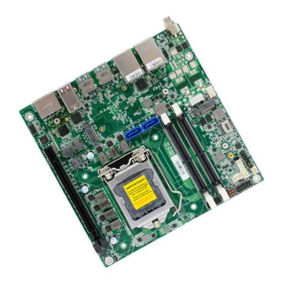
SIM Card Slot ▲LAN2 Caseopen ▼USB3.2 Gen2 M.2 E Key ▲LAN1 COM1 ▼USB3.2 Gen2 8-bit DIO DC-in Power Selection COM 1 M.2 B Key PCIe x16 DIO Power SATA1 Battery SATA0 SO-DIMM1 System Fan Front Panel SO-DIMM2 User's Manual | CMS171/CMS173... -
Page 10: Installing The Heat Sink
9 10 3. Screw tight two of the spring screws at opposite corners into the mounting holes. And then proceed with the other two spring screws. M.2 E Key M.2 B Key Mounting holes User's Manual | CMS171/CMS173... -
Page 11: Jumper Settings
9 10 M.2 E Key M.2 E Key M.2 B Key M.2 B Key „ 1-3 /2-4 On: „ 3-5 /4-6 On: „ 2-3 Off: Clear „ 1-2 On: Default RS232 Standard (Default) RS232 with Power User's Manual | CMS171/CMS173... -
Page 12: Pin Assignment
Chapter 2 HARDWARE INSTALLATION X Pin Assignment System Fan (J9) SATA Power (CN1) 9 10 9 10 M.2 E Key M.2 E Key M.2 B Key M.2 B Key Assignment Assignment +12V DC TACH +5V DC User's Manual | CMS171/CMS173... -
Page 13: Cpu Fan (J10)
Chapter 2 HARDWARE INSTALLATION CPU Fan (J10) DIO Power (J12) 9 10 9 10 M.2 E Key M.2 E Key M.2 B Key M.2 B Key Assignment Assignment 5VDU CTRL User's Manual | CMS171/CMS173... -
Page 14: Sata0 (J1)
Chapter 2 HARDWARE INSTALLATION SATA1 (J2) SATA0 (J1) 9 10 9 10 M.2 E Key M.2 E Key M.2 B Key M.2 B Key Assignment Assignment User's Manual | CMS171/CMS173... -
Page 15: Com1 (J17)
9 10 9 10 M.2 E Key M.2 E Key M.2 B Key M.2 B Key Assignment Assignment Assignment Assignment MDCD- MSIN- MIC2_L MSO- MDTR- MIC2_R -ACZ_DET MDSR- LINE2_R FSENSE1 MRTS- MCTS- FAUDIO_JD MRI- ---- LINE2_L FSENSE2 User's Manual | CMS171/CMS173... -
Page 16: Front Panel (J11)
Front Panel (J11) 9 10 9 10 M.2 E Key M.2 E Key M.2 B Key M.2 B Key Assignment Assignment Assignment DIO0 V_SUS_LED DIO1 DIO2 V_SUS_LED HDD_LED SUS_LED DIO3 DIO4 SYS_RST- PWR_BTN- DIO5 DIO6 DIO7 User's Manual | CMS171/CMS173... -
Page 17: Lpc (J14)
Chapter 2 HARDWARE INSTALLATION LPC (J14) 9 10 M.2 E Key M.2 B Key Assignment Assignment LAD1 RST# LAD0 FRAME# VCC3 LAD3 GND1 LAD2 SERIRQ GND2 5VSB User's Manual | CMS171/CMS173... -
Page 18: System Memory
DIMMs. Not all slots need to be populated. Dual Channel (DC) Data will be accessed in chunks of 128 bits from the memory channels. Dual channel provides better system performance because it doubles the data transfer rate. User's Manual | CMS171/CMS173... -
Page 19: Expansion Slots
4. Make sure the notch on card is aligned to the key on the socket. 5. Make sure the standoff screw is removed from the standoff. M.2 B Key M.2 Module M.2 Socket Stand-off Notch M.2 E-Key M.2 M-Key M.2 B-Key User's Manual | CMS171/CMS173... - Page 20 Screw tight the card onto the stand-off with a screw driver and a stand-off screw until the gap between the card and the stand-off closes up. The card should be lying parallel to the board when it’s correctly mounted. User's Manual | CMS171/CMS173...
-
Page 21: Chapter 3 - Bios Settings
“Press DEL to run setup” will appear on the screen. If the message disappears before you respond, restart the system or press the “Reset” button. You may also restart the system by pressing the <Ctrl> <Alt> and <Del> keys simultaneously. User's Manual | CMS171/CMS173... -
Page 22: Updating The Bios
MAC address should be burned or not. c. After updating unique MAC Address from manufacturing, NVM will be protected immediately after power cycle. Users cannot update NVM or MAC address. User's Manual | CMS171/CMS173... -
Page 23: Main
The time format is <hour>, <minute>, <second>. The time is based on the 24-hour military-time clock. For example, 1 p.m. is 13:00:00. Hour displays hours from 00 to 23. Minute displays min- utes from 00 to 59. Second displays seconds from 00 to 59. User's Manual | CMS171/CMS173... -
Page 24: Rc Acpi Settings
The system automatically powers on after power failure. • S5 State The system enter soft-off state after power failure. Power-on signal input is required to power up the system. • Last State The system returns to the last state right before power failure. User's Manual | CMS171/CMS173... -
Page 25: Power & Performance
Enable or disable CPU Power Management. It allows CPU to enter "C states" when it’s idle and Configure Intel(R) Active Management Technology Parameters. nothing is executing. ME Unconfig on RTC Clear When disabled, ME will not be unconfigured on RTC Clear. Firmware Update Configuration Configure Management Engine Technology Parameters. User's Manual | CMS171/CMS173... -
Page 26: Trusted Computing
WatchDog Timer Unit not available when "Security Device Support" is disabled. Select WatchDog Timer Unit — Second or Minute. SuperIO WatchDog Timer Set SuperIO WatchDog Timer Timeout value. The range is from 0 (disabled) to 255. User's Manual | CMS171/CMS173... -
Page 27: Nct5525D Super Io Configuration ► Serial Port 1 Configuration
NCT5525D Super IO Configuration ► Serial Port 1 Configuration NCT6126D HW Monitor This section displays the system’s health information, i.e. voltage readings, CPU and system temperatures, and fan speed readings Serial Port Enable or disable serial port. User's Manual | CMS171/CMS173... -
Page 28: Nct6126D Hw Monitor ► Smart Fan Function
Fan Speed Count 1 field. Fan Speed Count 1 to Fan Speed Count 4 Set the fan speed, the value ranging from 1-100%, 100% being full speed. The fans will op- erate according to the specified boundary temperatures above-mentioned. User's Manual | CMS171/CMS173... -
Page 29: Serial Port Console Redirection ► Console Redirection Settings
Enable or disable USB Mass Storage Driver Support. Stop Bits Select stop bits: 1 bit or 2 bits. Flow Control Select flow control type: None or Hardware RTS/CTS. Flow Control is for RS485 mode and is only supported by Serial Port 1 (COM1). User's Manual | CMS171/CMS173... -
Page 30: Network Stack Configuration
Other PCI devices Set the number of times the presence of media will be checked. Use either +/- or numeric Determines OpROM execution policy for devices otherthan Network, Storage, or Video. keys to set the value. User's Manual | CMS171/CMS173... -
Page 31: Usb Power Control
Chapter 3 BIOS SETTINGS Advanced USB Power Control Server CA Configuration 5_Dual: Support system wake up from S3/S4 by USB KB&MS 5V: No support system wake up from S3/54 by USB KB&MS User's Manual | CMS171/CMS173... -
Page 32: Chipset
Please select a submenu and press Enter. The submenus are detailed in the following pages. Primary Display Select which of IGFX/PEG/PCI Graphics device to be the primary display. Internal Graphics Keep IGFX "Enabled" or "Disabled" based on the setup options, or select "Auto" for auto-detec- tion. User's Manual | CMS171/CMS173... -
Page 33: Peg Port Configuration
PEG Port Configuration PEG Port Configuration ► PEG Port Feature Configuration Detect Non-Compliance Device Enable Root Port Detect Non-Compliance PCI Express Device in PEG Enable/Disable the Root Port Max Link Speed Configure PEG 0:1:0 Max Speed User's Manual | CMS171/CMS173... -
Page 34: Pch-Io Configuration
DXE and If VTD_INFO_PPI is installed in PEI. ) TBT tree won't be included in the exception list. DMA Control Guarantee Enable/Disable DMA_CONTROL_GUARANTEE bit. Hybrid Storage Mode Select Hybrid Storage detection and configuration Mode. User's Manual | CMS171/CMS173... -
Page 35: Security
Secure Boot. Press Enter and a prompt will show up for you to confirm. Reset To Setup Mode Clear the database from the NVRAM, including all the keys and signatures installed in the Key Management menu. Press Enter and a prompt will show up for you to confirm. User's Manual | CMS171/CMS173... -
Page 36: Boot
Refer to the Advanced > CSM Configuration submenu for more information. • Restore Setting from file This field will appear only when a USB flash device is detected. Select this field to restore set-ting from the USB flash device. User's Manual | CMS171/CMS173... -
Page 37: Updating The Bios
MAC address should be burned or not. c. After updating unique MAC Address from manufacturing, NVM will be protected immediately after power cycle. Users cannot update NVM or MAC address. User's Manual | CMS171/CMS173...
Need help?
Do you have a question about the CMS171 and is the answer not in the manual?
Questions and answers